Eschenbach 1621 User manual


The PDF-version of the guide for correct fitting of telescope magnifying systems can
be requested from Eschenbach Optik Nuremberg in the following languages with the
respective order number:
Language Order no.
German 162510
English 16251003
French 16251005
Spanish 16251006
Italian 16251007
Dutch 16251008
Danish 16251002

4 English
Safety instructions
FDanger of fire.
Lenses used in optical equipment may cause considerable damage through
their Ę"burning glass effect" if used or stored incorrectly. Ensure that optical
lenses are never left uncovered in the sunlight.
FMake sure that other people and especially children are aware of this.
FDanger of blinding or injury.
Never look at the sun through any optical equipment.
FProtect magnifying vision aids against jolts or impact and excessive heat!
Never place magnifying vision aids on heating elements or in the sun!
FMagnifying vision aids are only suitable for reading and may not be used for
driving!
FThe safety and care instructions listed must be explained to the user by the
fitter!
Magnifying vision aids
The term magnifying vision aid refers to all optical and electronic aids which assist a viĆ
sually impaired individual in seeing better through the use of his remaining visual acuity.
This already includes reading glasses with improved addition, simple hand magnifying
glasses, illuminated magnifying glasses or telescope magnifying systems of Kepler or
Galileo designs which contribute to improved vision.
The market even offers optical and electronic visual aids for the severely visually impaired
who have a remaining visual acuity of less than 10%. Of course, not every visual problem
can be solved or every desired acuity obtained. Generally, magnifying visual aids can be
fitted such that the daily work of the visually impaired individual within his household enviĆ
ronment can be performed without assistance from others. This restores more quality of life
to the visually impaired individual.
Consultation with an ophthalmologist is indispensable for providing visually impaired indiviĆ
duals with magnifying visual aids.
Definition of visual impairment
and its significance for the affected individual
An eye suffers from blunt vision Ć amblyopia Ć, if nothing approaching normal visual acuity
can be achieved even with full correction (visual acuity below 0.4). A visual impairment is
always a pathological change in the eye or an inner change resulting from an injury which
must be treated by an ophthalmologist. A decision regarding whether a magnifying vision
aid will even provide an improvement in vision can already be made to some extent after
diagnosis by a doctor. Frequently, a visually impaired individual goes directly to an optician
without a diagnosis; in this case, an ophthalmologist must be consulted at least during the
phase of the final decision. Without a doubt, the fitting of magnifying vision aids is signifiĆ
cantly more difficult than the fitting of normal corrective lenses, but can certainly be accomĆ
plished through the selection of the correct method and the correct means (system or
magnifying glass). The fitting of magnifying vision aids places high demands on the work of
the ophthalmologist and optician.

5English
Basic remarks on the provision of magnifying vision aids
Many diseases of the eye lead to a reduction in visual acuity. Diseases of the retina (maĆ
cula degeneration or retina deformation) and the optic nerves are the primary causes.
Magnifying vision aids have the task of compensating for this reduction in acuity through a
corresponding magnification of the retinal images.
FA visual acuity of approximately 0.1 (remaining visual acuity of 10%) is geneĆ
rally sufficient for orientation in the open in daylight.
FIn order to be able to clearly read newspaper print, a visual acuity of 0.4 - 0.5 is
typically sufficient under good lighting conditions
(Telephone book: 0.6 - 0.7 / timetable: 0.8).
FHowever, the acuity alone is not the only factor, reading ability is also imporĆ
tant. Reading is only possible if a minimum (5° diameter) amount of functional
retina is present.
FThe fitting of magnifying vision aids is called for with an acuitycc of less than 0.4.
Although many visually impaired individuals are primarily interested in obtaining help with
reading, a distance test must be performed. The determination of the refraction for the
visually impaired is intended to determine an optical correction with the best possible visual
acuitycc.
FThe acuitycc always remains the basis for the fitting of the magnifying vision aids.
Fundamentals
efore the fitting of magnifying vision aids, previously worn systems, glasses or magnifying
glasses must be inspected and the following values determined:
ĊDiopter values (sphere, cylinder, axis)
ĊPosition of the optical center
ĊVertex distance
ĊAddition (for bifocals, the seat of the near portion)
ĊSeat of the glasses frame, system support
ĊDiopter values of a previously used magnifying glass (diopter and magnification)
ĊData of a previously used system (magnification and useful distance)
The comparison of these values with the measurement results of the optometric examinaĆ
tion can provide important information as to whether the provision or prescription of a new
aid will be useful and effective.
Fitting systematic
1. The consultation with the visually impaired individual and the creation of a file:
ĊName, address, telephone, personal data
ĊIs the customer being treated by an ophthalmologist? (diagnosis, if available)
ĊName and address of the treating doctor
ĊForm a basis of trust with the customer, clarify his problems.
ĊWhat does the customer want to read? (desired vision)
ĊIs he still interested in reading or does he only want distance vision?

6 English
ĊFor how long has he not been reading? (very important!)
ĊEvaluation of his activity level
2. Explain about magnifying optical vision aids
ĊWeight
ĊAppearance (very important!) Comments from practice: ĘAre they funny-looking
glasses" or ĘAre these glasses ugly" ... and the entire success is put into question.
ĊWorking distance - reading is only possible from a certain distance
ĊLimitation of the field of vision
ĊGood lighting (halogen side lamp)
ĊReading material positioned as vertically as possible with respect to the viewing
angle (reading stand for comfortable support of material)
3. Selection of the required magnification in conn. with the existing acuity (acuitycc)
The required magnification for a vision aid is determined by the relationship between
the desired acuity (vision requirements) and the existing acuity (acuitycc with the best
possible glasses lenses).
RequiredĂmagnification +RequiredĂacuity
Acuitycc
Fitting of telescope magnifying glasses
Example: Galileo system 1621
Mr. Miller comes from an ophthalmologist with a prescription for monocular telescope
magnifying glasses for the right eye.
Indication: Retinal degeneration from diabetes.
We begin with the discussion and explanation of telescope magnifying glasses.
Mr. Miller is 60 years old and would like to be able to read the newspaper again.
In order to achieve the maximum visual capacity with a magnifying vision aid, it is necesĆ
sary to precisely determine the distance correction. First, one determines the unaided
acuity and then shifts to determination of the distance correction lens. If the inner condiĆ
tions of the eye (clouding of the media) permit that the corrective value (lens) can be deterĆ
mined in connection with the refractometer or skiascope, one makes use of these values
for the subjective refraction (today a computer vision test).
The subjective refraction is determined in the same manner as for normal glasses lenses
(according to the grading table for sph. and cyl. lenses).
Grading table for the best spherical lens
Acuity Grading
under 0.05 2.0 dpt min.
0.05-0.2 1.0 dpt
0.2-0.5 0.5 dpt
above 0.05 0.25 dpt

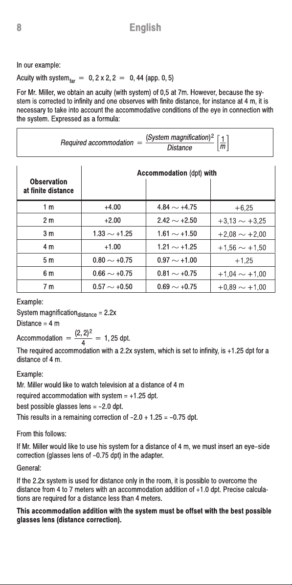
Acuity +2Ăm
8Ăm ĂxĂ0, 8 +0, 2
7English
Cylinder estimation table
Acuity Cylinder
1.0 0
0.5 1.0
0.25 2.0
0.12 3.0
0.06 4.0
Mr. Miller has an unaided acuity of 0.08/7m. The objective measurement yields approximaĆ
tely Ć2.0 dpt sph. According to the grading table for sph. lenses, we select for the first lens
Ć2.0 dpt sph. .
With the valued used, Ć2.0 sph. , we obtain an acuity of 0.2/7m. Through the subjective
comparison, we achieve no better acuity. Do not choose refraction steps which are too
small; the subject barely reacts to them and it can prolong the work unnecessarily.
The cylinder examination also yielded no improvement in acuity.
FTherefore, always proceed according to the grading table.
As significantly reduced acuity levels are often involved, it us useful to make use of a visual
examination board for the visually impaired. It is also possible to reduce the test distance
(which is often the simplest method). The acuity displayed by the projector is then no
longer valid. If the test distance and the projection distance are not equal, the following
formula applies:
Acuity +TestĂdistance
ProjectionĂdistanceĂxĂstatedĂacuity
(Test distance = reduced distance)
Example:
Reduced distance = 2 m
Projection distance = 8 m
Stated acuity = 0.8
The reduced refraction distance must be compensated for dioptrically (e.g. for 2 m =
+0.50 dpt). In our example (Mr. Miller), test distance = projection distance. Therefore, we
do not need to compensate for a reduced test distance.
We have now determined the best corrective glasses lens and the examination with the
magnifying system is performed. A magnifying system is used on the right side of the
refraction measurement glasses and the opposite side is covered with an opaque lens.
For non-focusable systems, it is always necessary to completely apply the distance
correction (sph. and cyl.) and to attach it to the system on the eye side.
What acuity can you expect with the Galileo system, modular linseatic, 2.2x?
AcuityĂwithĂsystemfar +AcuityĂwithoutĂsystemĂxĂsystemĂmagnificationfar
(Acuity without system = best possible acuity with glasses lenses)
Galilean system
2,0x
Galilean system
2,2x
Galilean system
2,5x
Galilean system
2,0x
Galilean system
2,2x
Galilean system
2,5x
1,88 x
2,50 x
3,13 x
3,75 x
5,00 x
6,25 x
7,50 x
10,00 x

AcuityĂwithĂsystemfarĂ+Ă 0, 2ĂxĂ2, 8 +Ă 0, 56Ă(app.Ă0, 6)
Nahvisus +0, 2ĂxĂ3, 4 +0, 70
10 English
Fitting of prismatic magnifying glasses
What acuity can you expect with the Kepler system, modular prismatic?
Example: Kepler system 2.8x
AcuityĂwithĂsystemfar +ĂAcuityccĂxĂSystemĂmagnificationfar
In our example, this results in:
Acuitycc = 0.20
System magnificationdistance = 2.8
For Mr. Miller, we obtain an acuity of 0.6 at 7 m.
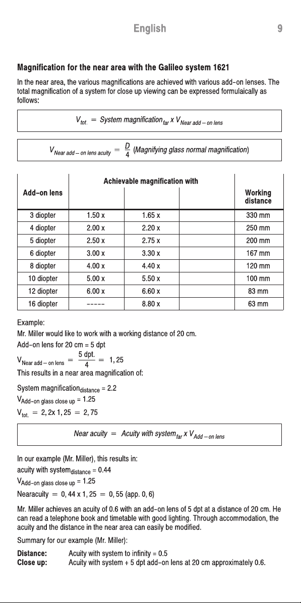
Magnification for the near area with the Kepler system 2.8x focusable
The asymmetrical correction and the accommodation addition need not be present for
focusable systems. The compensation is performed by turning the lens. However, stronger
cylinder lenses must be incorporated on the eye side. The maximum near magnification is
achieved by screwing out the lens the full distance.
NearĂ+ĂCorrectedĂacuityccĂxĂnearĂmagnificationsystem
For a focusable Kepler system, the near magnification is provided by the system (manufacĆ
turer information). The Kepler system 2.8x has a near magnification of 3.4x.
In our example, this results in:
Acuitycc = 0.20
Near magnificationsystem = 3.40
Mr. Miller achieves an acuity of 0.7 at 20 cm with the focusable system.
Summary for our example:
Distance: Acuity with system to infinity = 0.6
Close up: Acuity with system near area = 0.7
Our new Kepler systems can be supplemented with the various add-on lenses through the
use of an intermediate adapter.
This allows an increased magnification in the near area (! table page 15).
The fitting process (For Kepler and Galileo systems)
Selection of the system support
ĊSize of the mounting, stability, support surface in near area
Ċridge width
ĊHoop length
ĊMount inclination
ĊVertex distance (smaller corneal vertex distance)
efore we determine the centering data, the mount is fitted precisely.
Centering
ĊUse centering foil
ĊDetermine the eye distance according to the Victorin method
ĊObserve rotation point requirement
ĊIf necessary, inspect the centering with perforated labels
This manual suits for next models
21
Other Eschenbach Telescope manuals


