ESD electronic EPPC-405 User manual
EPPC-405 Hardware Manual Rev. 1.2
EPPC-405
Embedded PowerPC
with CAN and ETHERNET
Hardware Manual

EPPC-405 Hardware Manual Rev. 1.2
Document file: I:\texte\Doku\MANUALS\Embedded\EPPC-405\EPPC_12H.en9
Date of print: 02.08.2001
Chan
g
es in the chapters
The changes in the document affect changes in the hardware as well as descriptions of facts only.
Chapter Changes versus previous version
2.3 Pin assignment of power connector has changed!
-
Technical details are subject to change without notice.

EPPC-405 Hardware Manual Rev. 1.2
N O T E
The information in this document has been carefully checked and is believed to be entirely reliable. esd
makes no warranty of any kind with regard to the material in this document, and assumes no
responsibility for any errors that may appear in this document. esd reserves the right to make changes
without notice to this, or any of its products, to improve reliability, performance or design.
esd assumes no responsibility for the use of any circuitry other than circuitry which is part of a product
of esd gmbh.
esd does not convey to the purchaser of the product described herein any license under the patent rights
of esd gmbh nor the rights of others.
esd electronic s
y
stem desi
g
n
g
mbh
Vahrenwalder Str. 207
30165 Hannover
Germany
Phone: +49-511-372 98-0
Fax: +49-511-372 98-68
E-mail: [email protected]
Internet: www.esd-electronics.com
USA / Canada:
esd electronics Inc.
12 Elm Street
Hatfield, MA 01038-0048
USA
Phone: +1-800-732-8006
Fax: +1-800-732-8093
E-mail: [email protected]
Internet: www.esd-electronics.us

EPPC-405 Hardware Manual Rev. 1.2 1
Contents
1. Overview .................................................................... 3
1.1 Description of the EPPC-405-Computer ......................................... 3
1.2 Front Panel View with Connector Assignment ................................... 4
1.3 Dimensions for Installation ................................................... 5
1.4 Summary of Technical Data .................................................. 6
1.4.1 General Technical Data ................................................ 6
1.4.2 Power Supply ....................................................... 6
1.4.3 Serial Interface 1 (only Order No. I.2001.02) ............................... 7
1.4.4 CAN-Interface 1 (only Order No. I.2001.03) ............................... 7
1.4.5 Order Information .................................................... 8
2. Connector Assi
g
nment ........................................................ 9
2.1 Serial Interface 1 ........................................................... 9
2.2 CAN-Bus Interface 1 ....................................................... 10
2.3 Power Supply ............................................................. 11

EPPC-405 Hardware Manual Rev. 1.22
This page is intentionally left blank.
Overview
EPPC-405 Hardware Manual Rev. 1.2 3
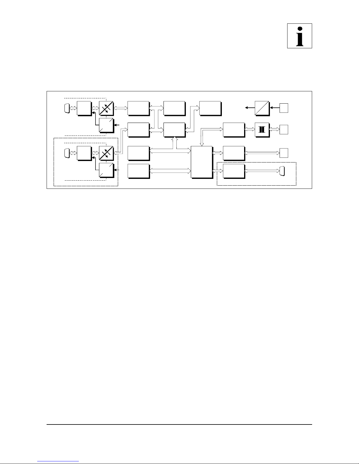
+5 V=
+5 V=
FPGA
Control Logic
CAN1
Flash
EPROM
NVRAM
IDE-
CompactFlash
Interface
RJ45
10/100BaseT
10/100BaseT
Transceiver
DSUB9
Serial 1
RS-232
RS-232
Interface
+5 V=
+5 V=
electrical isolation
DC/DC
Converter
DSUB9
CAN1
Physical
CAN
Layer
CAN0
RJ11
Serial 0
RS-232
RS-232
Interface
electrical isolation
DC/DC
Converter
DSUB9
CAN0
CAN Controller
SJA1000
SDRAM
CAN Controller
SJA1000
Physical
CAN
Layer
IBM
PPC405GP
Only with Order no I.2001.03 Only with Order no I.2001.02
Combicon-
Style
Power Supply
24 V
5 V
3,3 V
Power Supply
1. Overview
1.1 Descri
p
tion of the EPPC-405-Com
p
uter
Fi
g
. 1.1.1: Block-circuit diagram
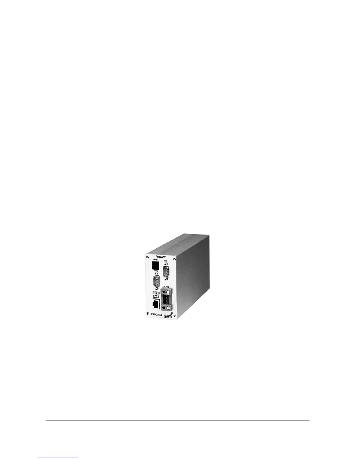
The EPPC-405 is a compact PowerPC computer with various bus interfaces. It includes the PowerPC
board CPCI-405 and a 24 V mains adaptor. Apart from the CompactPCI-bus connection all functions
of the CPCI-405 board can also be used in the EPPC-405 computer. Therefore, the included CPCI-405
manual can also be used to operate this computer. The first part of this documentation explains the
features of the EPPC-405 which are not covered by the CPCI-405 documentation.
Specific for the EPPC-405 are the following:
- installation of case
- power supply with 24 V
- a second CAN-interface at DSUB9-connector in front panel
- a second serial interface at DSUB9-connector in front panel

Overview
EPPC-405 Hardware Manual Rev. 1.24
CAN
RUN
LNK
RCV
SER0
1
2
3
4
5
6
7
8
9
1
2
3
4
5
6
7
8
9
Power
CAN0
SER1/
CAN1
Fast Ethernet
Alternative:
Order-No. I.2001.02:
RS-232 Interface SER1
Order-No. I.2001.03:
CAN Interface CAN1
Power Supply 24VDC
Ethernet 10/100BaseT
LED Display
CAN Interface CAN0
RS-232 Interface SER0
EPPC/405
1.2 Front Panel View with Connector Assi
g
nment
Fi
g
. 1.2.1: Front panel view
Overview
EPPC-405 Hardware Manual Rev. 1.2 5
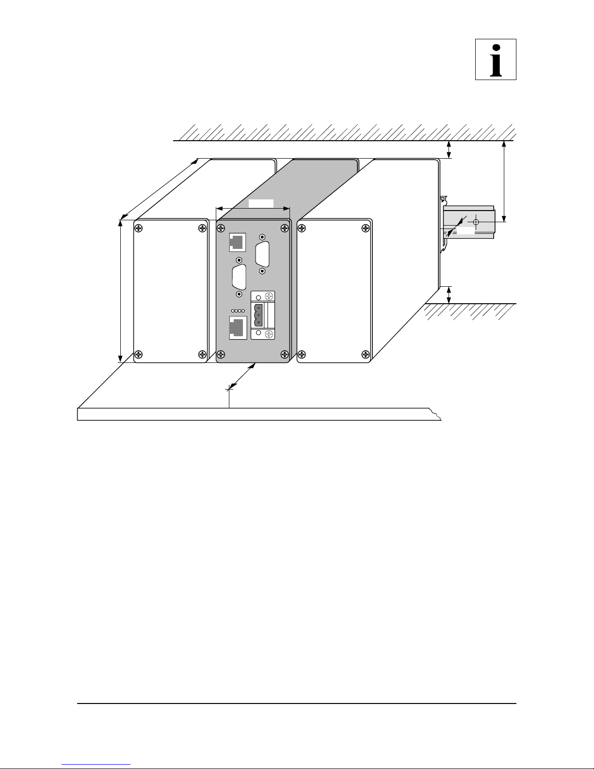
184 mm
55 mm
105 mm
55 mm
72,5 mm
20 mm
EPPC-405
20 mm
4 mm
1.3 Dimensions for Installation
Fi
g
. 1.3.1: Dimensions of the EPPC-405 for installation

Overview
EPPC-405 Hardware Manual Rev. 1.26
1.4 Summar
y
of Technical Data
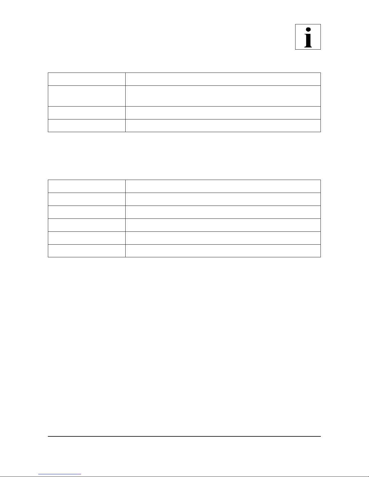
1.4.1 General Technical Data
Ambient temperature 0...50°C
Humidity max. 90 %, non-condensing
Connectors
SER0 (6-pin RJ11-female) - RS-232 interface (Serial 0)
CAN0 (9-pin DSUB-male) - CAN 0 (ISO11898)
Ethernet
10/100
(8-pin RJ45-female) - ETHERNET Twisted
Pair (IEEE 802.3)
Power (3-pin Combicon) - power supply 24 V
SER1/
CAN1
EPPC-405-order no. I.2001.02:
(9-pin DSUB-female) RS-232 interface (Serial 1)
EPPC-405-order no. I.2001.03:
(9-pin DSUB-female) CAN 1 (ISO11898)
Dimensions 105 x 55 x 200 mm (without connectors and hat-rail holder)
Weight 750 g
Table 1.4.1: General technical data
1.4.2 Power Suppl
y
Input voltage 24 V / DC ± 10 %
Power 7.2 W
Connector 3-pin screw/plug connector in Combicon design
Table 1.4.2: Power supply
Overview
EPPC-405 Hardware Manual Rev. 1.2 7
1.4.3 Serial Interface 1 (onl
y
Order No. I.2001.02)
Drive PPC405GP
Bit rate micro controller: 1200 bit/s ... 312. 500 kbit/s
RS-232 transceiver: max. 38.4 kbit/s
Physical interface RS-232C
Connector 9-pin DSUB-female in front panel
Table 1.4.3: Serial interface 1
1.4.4 CAN-Interface 1 (onl
y
Order No. I.2001.03)
CAN-controller SJA1000
CAN-protocol CAN 2.0A/2.0B
Physical interface differential, connection in accordance with ISO 11898
Transmission rate 10 kbit/s ... 1 Mbit/s
Bus termination has to be set externally
Connector DSUB9-female in front panel
Table 1.4.4: CAN-interfaces

Overview
EPPC-405 Hardware Manual Rev. 1.28
1.4.5 Order Information
Type Features Order No.
EPPC-405 IBM PPC405GP, 200 MHz, 16 MB SDRAM, 4
MB Flash, 2x RS-232, 1x CAN
I.2001.02
IBM PPC405GP, 200 MHz, 16 MB SDRAM, 4
MB Flash, 1x RS-232, 2x CAN
I.2001.03
EPPC-405-ME *) English manual I.2001.21
*) If manual and product are ordered together, the manual is free of charge.
Table 1.4.5: Order information

Connector Assignment
EPPC-405 Hardware Manual Rev. 1.2 9
2. Connector Assi
g
nment
For the assignment of connectors for serial interface 0, CAN-interface 0 and the Ethernet interface
please refer to the CPCI-405 manual. In this chapter only the connectors will be described which are
not on the CPCI-405 board.
2.1 Serial Interface 1 (SER1)
Pin Position:
Pin Assi
g
nment:
Si
g
nal Pin Si
g
nal
n.c. 1
6 n.c.
RxD (output) 2
7 reserved
TxD (input) 3
8 reserved
reserved 4
9 n.c.
GND 5
9-pin female DSUB
n.c. ... not connected
The signal names are stated as seen from the terminal (PC). The data direction given in brackets is as
seen from the CPCI-405 board.

Connector Assignment
EPPC-405 Hardware Manual Rev. 1.210
2.2 CAN-Bus Interface 1 (CAN 1)
Pin Position:
Pin Assi
g
nment:
Si
g
nal Pin Si
g
nal
1 reserved
CAN_GND 6
2 CAN_L
CAN_H 7
3 CAN_GND
reserved 8
4 reserved
reserved 9
5 shield
9-pin female DSUB
Si
g
nal Description:
CAN_L, CAN_H ... CAN-signal lines
CAN_GND ... reference potential of the local CAN-physical layer
shield ... potential of connector case
reserved ... reserved for future applications
Connector Assignment
EPPC-405 Hardware Manual Rev. 1.2 11
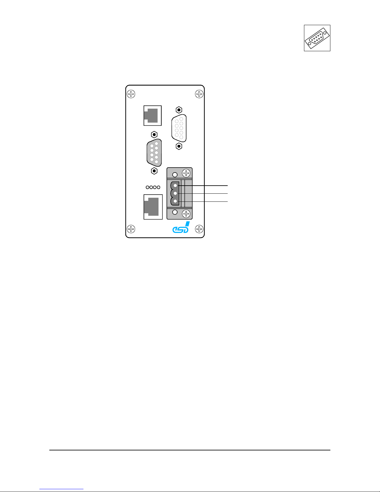
CAN
RUN
LNK
RCV
SER0
1
2
3
4
5
6
7
8
9
1
2
3
1
2
3
4
5
6
7
8
9
Power
CAN0
SER1/
CAN1
Fast Ethernet
EPPC/405
Shield
+24 VDC
GND
2.3 Power Su
pp
l
y
Table of contents
Other ESD electronic Recording Equipment manuals


