esera 12002 Quick guide
Art. No. 12002
All rights reserved. Reprinting, including excerpts, not permitted without the express consent of ESERA GmbH.
Subject to technical changes. ESERA GmbH 2023
www.esera.de 12002 V2.0 R1.1 configuration ETH Page 1 from 7
Configuration
eBus coupler Ethernet
Configuration of the Ethernet interface for TCP and UDP operation
1 INTRODUCTION
In order to commission or configure the eBus coupler under Windows® , the installation of the "Configuration-
Tool" (hereafter called Config-Tool) is necessary.
This manual describes the installation of the "Configuration Tool" (hereafter called Config Tool) and configuration
of the Ethernet interface under Windows 7®.
Execute the installation with administrator rights.
This manual is applicable for the following versions of the eBus coupler:
Art. No. 12002 eBus coupler Ethernet
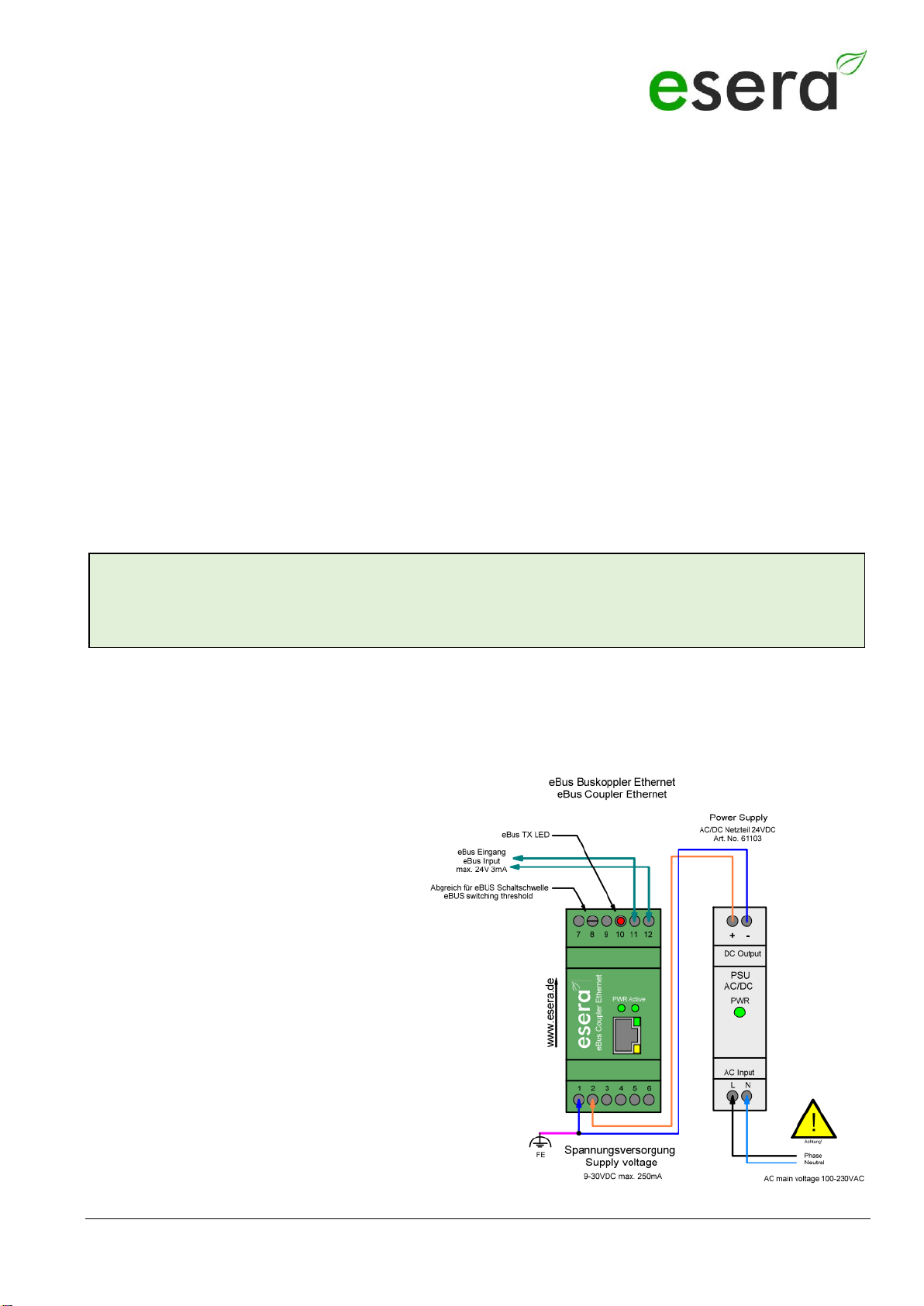
2 PREPARATION, COMPARISON eBus
After connecting the eBus coupler with the power supply and a network cable to a PC, the power LED on the top
of the device lights up and signals that the device is ready for operation.
For details on adjusting the eBus level, please refer to the current operating instructions for the device
2.1 CONNECTION
eBus connection
(module top side)
7 = not used
8 = Trimmer for response point
9 = Not assigned
10 = LED display for eBus
11 = eBus
12 = eBus
Power supply connection
(module underside)
1 = minus
2 = Plus
3 - 6 = not used
Note
Before you start assembling the device and put it into operation, read this manual carefully to the end,
especially the section on safety instructions.
All rights reserved. Reprinting, including excerpts, not permitted without the express consent of ESERA GmbH.
Subject to technical changes. ESERA GmbH, 2023
www.esera.de 12002 V2.0 R1.1 configuration ETH Page 2 from 7
3 TERMINAL PROGRAM / PROTOCOL
The eBus coupler with Ethernet interface (Art. No. 12002) translates the running data of the eBus for different
programs via TCP or UDP data transfer.
As test program e.g. the program "Hercules" or Putty
may be used.
Hercules: http://www.hw-group.com/products/hercules/index_en.html
Putty: http://www.chiark.greenend.org.uk/~sgtatham/putty/download.html
4 SOFTWARE DOWNLOAD
Copy the downloaded zip file to any directory.
Unzip the zip file e.g. with the free software 7-Zip (http://www.7-zip.de/)
5 WINDOWS PORT RELEASE
For the communication between eBus coupler and your Windows control software, e.g. IP-Symcon, Putty or
Hercules, a release of the selected port of the Config-Tool under Windows is necessary.
Unfortunately, it is not enough to disable the firewall, but you must explicitly enable the ports for sending and
receiving via TCP and/or UDP in Windows.
You can find the activation under WINDOWS:
Control Panel / System and Security / Windows Firewall / Advanced Settings
=> Incoming rules
=> Outgoing rules
Note
The module may only be operated at the voltages and under the ambient conditions specified for it. The
operating position of the device is arbitrary.
The modules may only be commissioned by a qualified electrician.
Further information on the operating conditions can be found in the operating instructions for the under
"Operating conditions".
Art. No. 12002
All rights reserved. Reprinting, including excerpts, not permitted without the express consent of ESERA GmbH.
Subject to technical changes. ESERA GmbH 2023
www.esera.de 12002 V2.0 R1.1 configuration ETH Page 3 from 7
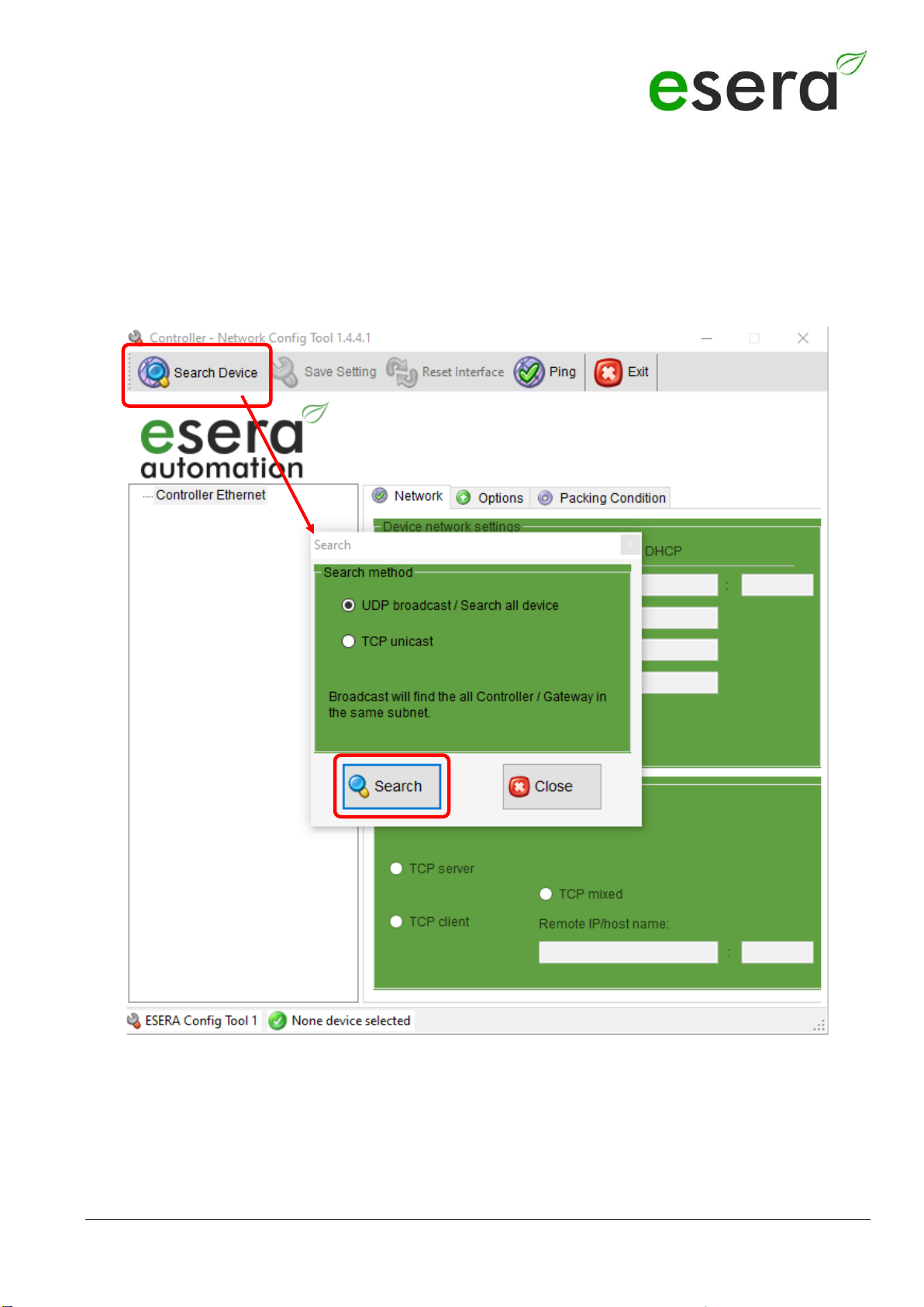
6 Start "ESERA CONFIG TOOL 1"
Connect the eBus coupler Ethernet to your IP network and a suitable
power supply (9-30VDC min. 0.5A) and switch it on.
The green LEDs on the front panel (PWR) and inside the network socket should light up.
Start the "ESERA CONFIG TOOL 1".
•Click on the button "Search" to search the eBus coupler in the Ethernet network.
•Another search field opens. Click on the "Search" button. The search may take a few seconds. It is not
necessary to enter anything in the search mask here.
All rights reserved. Reprinting, including excerpts, not permitted without the express consent of ESERA GmbH.
Subject to technical changes. ESERA GmbH, 2023
www.esera.de 12002 V2.0 R1.1 configuration ETH Page 4 from 7
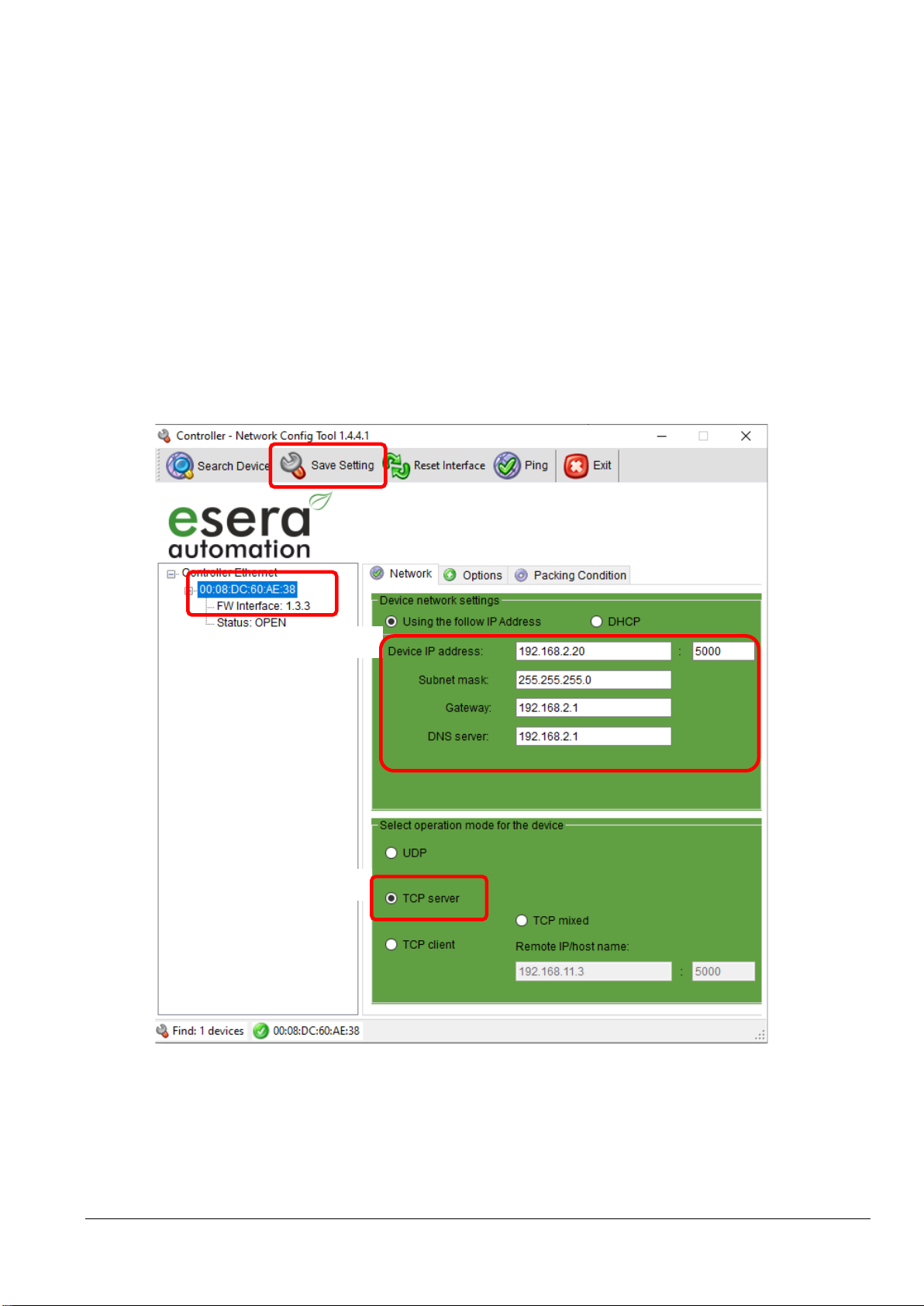
7 SETTINGS TCP SERVER
You may assign an IP address to the eBus coupler Ethernet via DHCP server or set it to a fixed IP address.
We recommend the operation with a fixed IP address.
Settings
If you set the IP address to fixed, the settings for gateway and DNS server are also fixed.
to be entered. The module must be operated in the same subnet as your computer.
Select TCP Server
Settings (example)
•Fixed IP address 192.168.2.20
•Subnet Mask 255.255.255.0
•Gateway: 192.168.2.1
•DNS Server: 0.0.0.0
1: MAC address of the eBus coupler,
2: IP address, subnet mask and gateway and port, e.g. 5000
3: Operating mode: TCP server
Saving the settings
Save the settings via the "Save Setting" button. This completes the configuration of the interface
Note:
Clicking the "Factory" button restores the factory settings of the Ethernet interface, but not the settings of the
delivery state.
1
3
2
Art. No. 12002
All rights reserved. Reprinting, including excerpts, not permitted without the express consent of ESERA GmbH.
Subject to technical changes. ESERA GmbH 2023
www.esera.de 12002 V2.0 R1.1 configuration ETH Page 5 from 7
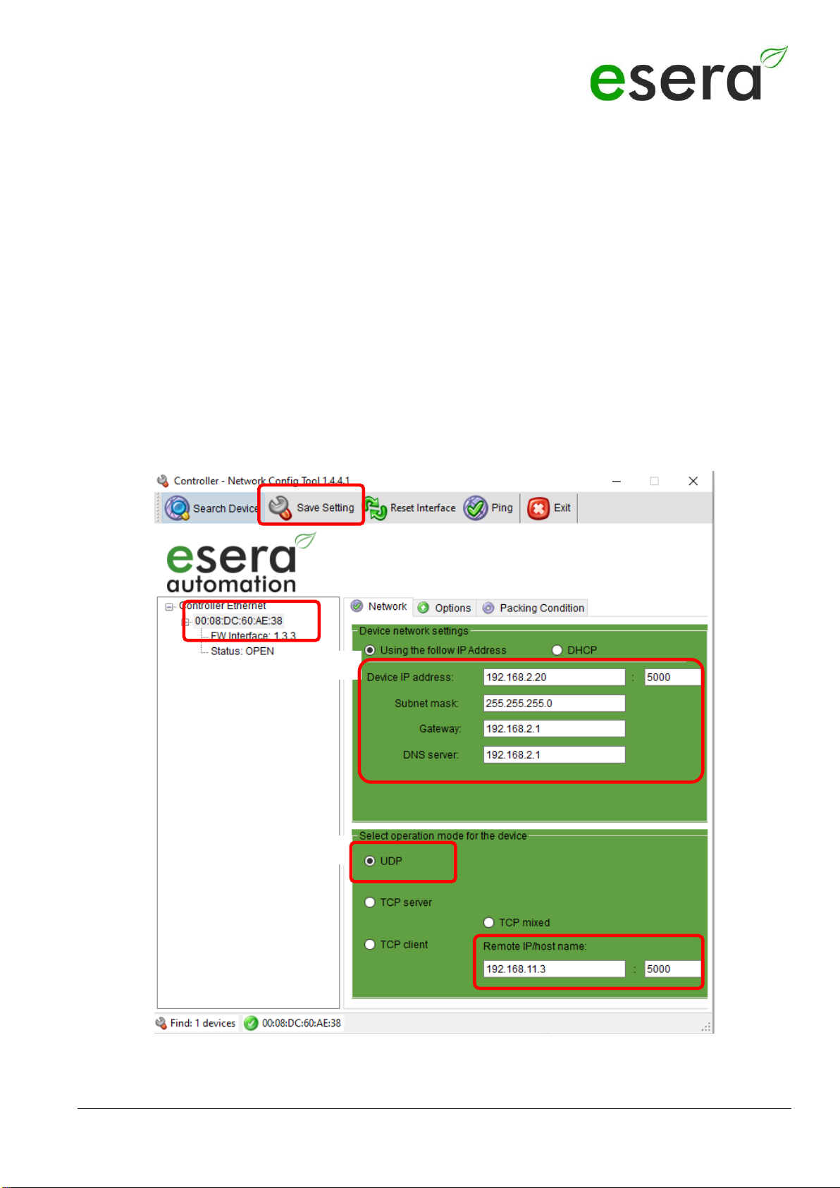
8 SETTINGS UDP SERVER
You may assign an IP address to the eBus coupler Ethernet via DHCP server or set it to a fixed IP address. We
recommend the operation with a fixed IP address.
Settings
If you set to fixed IP address, the gateway and DNS server settings are also
to be entered. The module must be operated in the same subnet as your computer Select UDP server.
Settings
•Fixed IP address 192.168.2.20
•Subnet Mask 255.255.255.0
•Gateway: 192.168.2.1
•DNS server: 192.168.2.1
1: MAC address of the 1-Wire controller 1
2: IP address, subnet mask and gateway and port: e.g. 5000
3: Operating mode: UDP server, IP address and port of the control system.
To be able to establish a data connection with the control system, the entry of the
IP address and the port is necessary.
Saving the settings
1
3
2
All rights reserved. Reprinting, including excerpts, not permitted without the express consent of ESERA GmbH.
Subject to technical changes. ESERA GmbH, 2023
www.esera.de 12002 V2.0 R1.1 configuration ETH Page 6 from 7
Save the settings via the "Save Setting" button. This completes the configuration of the module
9 OPERATING CONDITIONS
The module may only be operated at the voltages and under the ambient conditions specified for it. The operating
position of the device is arbitrary. The device is intended for use in dry and dust-free rooms. Do not operate the
module in an environment where flammable gases, vapors or dusts are or could be present.
If condensation forms, wait for an acclimatization period of at least 2 hours.
The modules may only be commissioned by a qualified electrician.
10 ASSEMBLY
The mounting location must be protected from moisture. The device may only be used in dry indoor areas.
The device is intended for mounting inside a control cabinet as a stationary device.
11 DISPOSAL NOTICE
Do not dispose of the device in household waste! Electronic devices are to be disposed of
according to
of the Directive on Waste Electrical and Electronic Equipment on the local
Collection points for electronic waste to dispose of!
12 SAFETY INSTRUCTIONS
When handling products that come into contact with electrical voltage, the applicable VDE regulations must be observed, in
particular VDE 0100, VDE 0550/0551, VDE 0700, VDE 0711 and VDE 0860.
•All termination and wiring work may only be carried out when the device is de-energized.
•Before opening a device, always disconnect the power plug or ensure that the device is de-energized.
•Components, assemblies or devices may only be put into operation if they have previously been installed in a
housing in such a way that they are safe to touch. They must be de-energized during installation.
•Tools may only be used on devices, components or assemblies if it has been ensured that the devices are
disconnected from the supply voltage and that electrical charges stored in the components located in the device
have been discharged beforehand.
•Live cables or lines to which the device, component or assembly is connected must always be inspected for
insulation faults or breaks.
•If a fault is detected in the supply line, the device must be taken out of operation immediately until the defective line
has been replaced.
•When using components or assemblies, attention must always be drawn to strict compliance with the characteristic
data for electrical variables specified in the associated description.
•If it is not clear for the non-commercial end user from an existing description which electrical characteristic values
apply to a component or an assembly, how external wiring is to be carried out or which external components or
additional devices may be connected and which connection values these external components may have, a qualified
electrician must be consulted.
•Before commissioning a device, it must generally be checked whether this device or the assembly is fundamentally
suitable for the application for which it is to be used.
•In case of doubt, it is essential to consult specialists, experts or the manufacturer of the assemblies used.
•We do not accept any liability for operating and connection errors that are beyond our control.
•Kits should be returned with a precise description of the fault and the associated assembly instructions without the
housing in the event of malfunction. Without error description a repair is not possible. We have to charge extra for
time-consuming assembly or disassembly of housings.
•It is essential that the relevant VDE regulations are observed during installations and when handling parts that will
later carry mains voltage.
•Devices that are operated at a voltage greater than 35 VDC/12mA may only be connected and commissioned by
qualified electricians.
•Commissioning may only be carried out if the circuit is installed in a housing so that it is safe to touch.
•If measurements are unavoidable with the housing open, a safety isolating transformer must be connected upstream
for safety reasons, or a suitable power supply unit must be used.
•After installation, the required test must be performed in accordance with DGUV Regulation 3.

Art. No. 12002
All rights reserved. Reprinting, including excerpts, not permitted without the express consent of ESERA GmbH.
Subject to technical changes. ESERA GmbH 2023
www.esera.de 12002 V2.0 R1.1 configuration ETH Page 7 from 7
13 WARRANTY
ESERA GmbH warrants that the goods sold are free from material and manufacturing defects at the time of transfer of risk
and that they have the contractually warranted characteristics. The statutory warranty period of two years from invoicing
applies. The warranty does not cover normal wear and tear. Claims of the customer for damages, e.g. due to non-
performance, culpa in contrahendo, breach of ancillary contractual obligations, consequential damages, damages in tort and
other legal grounds are excluded. ESERA GmbH shall be liable, however, in the absence of a warranted characteristic, in the
case of intent or gross negligence. Claims from the product liability law are not affected by this. If defects occur for which
ESERA GmbH is responsible, and if in case of exchange of the goods also the replacement delivery is defective, the
purchaser has the right to rescission or reduction of the purchase price. ESERA GmbH assumes no liability neither for the
constant and uninterrupted availability of ESERA GmbH nor for technical or electronic errors of the online offer.
We are constantly developing our products and reserve the right to make changes and improvements to any of the products
described in this documentation without prior notice. If you need documentation or information on older versions, please
14 WARNING
All listed designations, logos, names and trademarks (including those that are not explicitly marked) are trademarks,
registered trademarks or other designations protected by copyright or trademark or title law of their respective owners and
are expressly recognized by us as such. The mention of these designations, logos, names and trademarks is for
identification purposes only and does not constitute any kind of claim by ESERA GmbH to these designations, logos,
names and trademarks. Furthermore, the appearance on the web pages of ESERA GmbH does not imply that
designations, logos or names are free of industrial property rights.
ESERA and Auto-E-Connect are registered trademarks of ESERA GmbH.
Auto-E-Connect is registered as a German and European patent by ESERA GmbH.
ESERA GmbH is a promoter of the free Internet, free knowledge and the free encyclopedia Wikipedia.
We are a member of Wikimedia Deutschland e.V., the provider of the German site Wikipedia
(https://de.wikipedia.org).
Wikimedia Deutschland's purpose is to promote free knowledge.
Wikipedia® is a registered trademark of the Wikimedia Foundation Inc.
15 CONTACT
ESERA GmbH
Adelinda street 20
D-87600 Kaufbeuren
Germany
Tel.: +49 8341 999 80-0
Fax: +49 8341 999 80-10
www.esera.de
WEEE number: DE30249510
Table of contents


