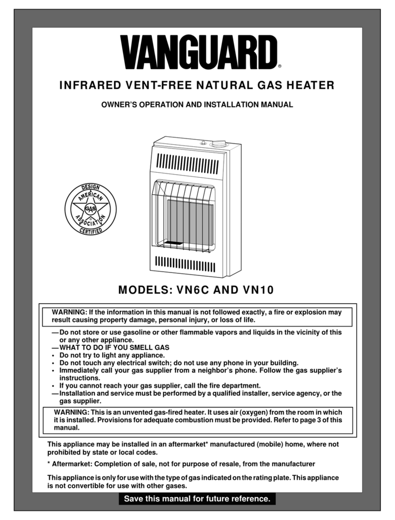
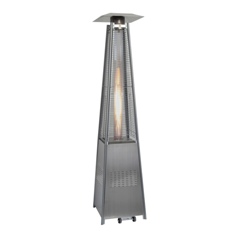
Eskabe S21 Mini 3 Specification sheet

- 1 -
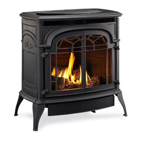
Unvented Gas Room Heater
Models:
Manually Controlled
S21 Mini 3
S21 Mini 5
S21 Mini 8
With Thermostat
S21 Mini 3 TE
S21 Mini 5 TE
Before Installing this heater, read all instructions in this manual
carefully. Check all local codes.
This is an unvented gas-fired heater. It uses air (oxygen) from the
room in which it is installed. Provisions for adequate combustion
and ventilation air must be provided.
OWNER´S OPERATON
AND INSTALLATION MANUAL

- 2 -
Installation and repair should be done by a qualified service person.
The appliance should be inspected before use and at least annually
by a qualified service person. More frequent cleaning may be
required due to excessive lint from carpeting, bedding material, etc.
It is imperative that control compartments, burners and circulating air
passageways of the appliance be kept clean.
Specifications
Model S21 Mini 3 S21 Mini 5 S21 Mini 8
Heat Input
3000 Kcal/h ( 3.49 Kw)
Based on Gross Calorific
Value.
5000 Kcal/h ( 5.81 Kw)
Based on Gross Calorific
Value.
8000 Kcal/h (9.30Kw)
Based on Gross Calorific
Value.
Burner Orifice Natural Gas 1.45 mm
LPG – Propane 1.00 mm
Natural Gas 1.95 mm
LPG – Propane 1.25 mm
Natural Gas 2.45 mm
LPG – Propane x 1.65 mm
Type of gas Natural Gas
or
LPG - Propane
Natural Gas
or
LPG - Propane
Natural Gas
or
LPG - Propane
Model S21 Mini 3 TE S21 Mini 5 TE
Heat Input
2000 Kcal/h ( 2.30 Kw)
Based on Gross Calorific
Value.
3000 Kcal/h ( 3.49 Kw)
Based on Gross Calorific
Value.
Burner Orifice Natural Gas 1.45 mm
LPG – Propane 1.00 mm
Natural Gas 2.10 mm
LPG – Propane 1.25 mm
Type of gas Natural Gas
or
LPG - Propane
Natural Gas
or
LPG - Propane
This unit is equipped with an oxygen depletion safety system (O.D.S.). The
oxygen depletion safety system allows safe vent-free operation. When the
normal oxygen content (20.9%) is reduced to 18%, the pilot and main burner
will turn off and cannot be relit.
When the pilot flame is extinguished by wind or interruption of gas supply, it will
also turn off. Relighting is possible in this condition.
All models, except Mini 8, are fitted with a pressure regulator for Natural Gas.
The thermostat fitted to the models S21 Mini 3 TE and S21 Mini 5 TE, operates
from a maximum to a minimum input power of the main burner, as required by
the temperature in the room.

- 3 -
Dimensions Model S21 Mini 3 / S21 Mini 3 TE
Fig. 1a
Model S21 Mini 5 / S21 Mini 5 TE
Fig. 1b

- 4 -
Model S21 Mini 8
Fig. 1c
Installation
This appliance is wall mounted. The minimum clearance from the floor to the bottom
of the heater is 12 cm. However, for a comfortable operation, it is recommended to
install the appliance with a clearance of 25 cm. from floor to bottom.
Never install the heater on the floor.
Fig. 2
Locating the Heater
•Define the height H at which the heater will be installed.
•Draw a horizontal line at a height H + 45,5 cm.

- 5 -
•Mark and drill the holes for the fixing anchors. For model Mini 8 a third hole
must be done. See figure 1c.
•Screw the upper fixing screws some turns in the anchors.
•Separate the front panel of the appliance by removing the two nuts at the
bottom and slide it up. See figure 3
•Hang heater on fixing screws by means of holes provided at the rear of the
heater.
•In model Mini 8, place and fix the bottom fixing screw.
Fig. 3
•Connect the appliance to the gas supply line. The materials used must
conform the local codes and standards.
•Once the appliance is connected, check for leaks. Use liquid detergent in
all joints. Never use a flame to look for gas leaks.
•Reassemble the heater, slide the front panel through the front edges of the
cabinet back as shown in figure 4.
•Place the screws, and fix them.

- 6 -
Cabinet Back Bolts with Nuts
Front Panel
Grid
Front Edges
Fig. 4
NOTE: It is normal for a new appliance to give off some odor the first time it is lit.
This is due to the curing of the paint and any undetected oil from the manufacturing
process.
It is recommended to secure a good room ventilation for at least two (2) hours the
first time the heater is used.
Installing the Thermostat Sensor (Fig. 5) - TE Models (with Thermostat)
Once the heater is installed proceed to install the thermostat sensor bracket.
Extract the bulb from the bracket.
The bracket must be fixed horizontally to the wall, with the screws provided. It must
be placed at 1 cm. over the bottom of the heater, and approximately 2 cm. from the
right side of the heater.
When the bracket is fixed to the wall, place the sensor again in the bracket.
Fig. 5

- 7 -
Lighting Instructions - Standard Models (Fig. 6)
•Open the main gas valve.
•Push in the gas control knob from z(Off) and turn it to (Pilot) position
(Fig. 6).
•Depress knob and, after five seconds, push in the ignitor button.
•Observe through the view port if the pilot is lit. If not, repeat the previous
operation.
•Keep control knob depressed for 20 seconds before releasing. Turn control
knob to the desired position (Maximum) or (Minimum).
•To turn off the heater, turn control knob to position (Off) and close the
main gas valve.
Fig. 6
Lighting Instructions Thermostatic Models (Fig. 7)
•Open the main gas valve.
•Push in the gas control knob from z(Off) and turn it to (Pilot) position
(Fig. 7).
•Depress knob and, after five seconds, push in the ignitor button.
•Observe trough the view port if the pilot is lit. If not, repeat the previous
operation.
•Keep control knob depressed for 20 seconds before releasing.
•Turn control knob to the desired position TE position.
•To turn off the heater, turn control knob to position (Off) and close
the main gas valve.
•Never turn the Control Knob in positions between (Pilot) and TE.
Thermostat Knob Operation
This knob must be positioned to the desired ambient tempertature. As a
reference the usual temperatures for home heating are from 20 ºC to 24 ºC.

- 8 -
Fig. 7
Cleaning and Maintenance
Turn off the heater and let it cool down before cleaning or maintenance.
Verify proper operation after servicing.
You must keep control areas and circulating air passageways of heater clean.
Inspect these areas of the heater before each use. Have heater inspected yearly by
a qualified service person. Heater may need more frequent cleaning due to
excessive lint from carpeting, bedding material, etc.
CABINET
Exterior
Use a soft cloth dampened with a mild soap and water mixture. Wipe the cabinet to
remove dust.
Air Passageways
Use a vacuum cleaner or pressurized air to clean.
Vent Cap
Use a vacuum cleaner or pressurized air to clean.
Pilot and Burner
Periodically make a visual check of the pilot and burner flames.
(View flames through view port)

- 9 -
Troubleshooting
OBSERVED PROBLEM POSSIBLE CAUSE REMEDY
When ignitor button is pressed,
there is no spark at ODS/pilot 1) Ignitor electrode positioned
wrong.
1) Replace ignitor
2) Ignitor electrode broken. 2) Replace ignitor
3) Ignitor electrode not
connected to ignitor cable. 3) Reconnect ignitor cable
4) Ignitor cable pinched or
wet.
4) Free ignitor cable if pinched by
any metal or tubing. Keep ignitor
cable dry.
5) Piezo ignitor nut is loose 5) Tighten nut holding piezo ignitor
to heater cabinet. Nut is located
inside heater cabinet at bottom.
6) Broken ignitor cable 6) Replace ignitor cable
7) Bad piezo ignitor 7) Replace piezo ignitor
When ignitor button is pressed,
there is spark at ODS/pilot but
no ignition.
1) Gas supply is turned off or
manual shutoff valve closed 1) Turn on gas supply or open
manual shutoff valve
2) Control knob not in PILOT
position 2) Turn control knob to PILOT
position.
3) Control knob not pressed
in while in pilot position. 3) Press in control knob while in
PILOT position.
4) Air in gas lines when
installed. 4) Continue holding down control
knob. Repeat igniting operation until
air is removed.
5) ODS/pilot is clogged. 5) Clean ODS/pilot (see Cleaning
and maintenance, page 16) or
replace ODS/pilot assembly.
6) Gas regulator setting not
correct Replace gas regulator.
ODS/pilot lights but flame goes
out when control knob is
released.
1) Control knob not fully
pressed in. 1) Press in control knob fully.
2) Control knob not
depressed long enough 2) After ODS/pilot lights, keep
control knob pressed in 30 seconds.
3) Manual shutoff valve not
fully open. 3) Fully open manual shutoff valve.
4) Thermocouple connection
loose at control valve. 4) Hand tighten until snug, then
tighten ¼ turn more.
5) Pilot flame not touching
thermocouple, which allows
couple to cool, causing pilot
flame to go out. This problem
could be caused by one or
both of the following:
a) Low gas pressure.
b) Dirty or partially clogged
ODS/pilot
5)
a) Contact local gas company.
b) Clean ODS/pilot or replace
ODS/pilot assembly.
6) Thermocouple damaged 6) Replace thermocouple
7) Control valve damaged 7) Replace control valve
Burner does not light after
ODS/pilot is lit. 1) Burner orifice is clogged. 1) Clean burner or replace burner
orifice.
2) Burner orifice diameter is
too small. 2) Replace burner orifice.
3) Inlet gas pressure is too
low. 3) Contact local gas company.

- 10 -
Delayed ignition of burner. 1) Manifold pressure is too
low. 1) Contact local gas company.
2) Burner or pilot orifice is
clogged 2) Clean burner or pilot (see
Cleaning and maintenance, page
16) or replace orifice.
Burner backfiring during
combustion 1) Burner orifice is clogged or
damaged. 1) Clean burner (see Cleaning and
Maintenance, page 16) or replace
burner orifice.
2) Burner damaged. 2) Replace burner.
3) Gas regulator defective 3) Replace gas regulator.
Yellow flame during burner
combustion. 1) Not enough air. 1) Check burner for dirt and debris.
If found, clean burner.
2) Gas regulator defective 2) Replace gas regulator.
Slight smoke or odor during
initial operation 1) Residues from
manufacturing processes. Problem will stop after a while of
operation.
Heater produces a whistling
noise when burner is lit. 1) Turning control knob to HI
position when burner is cold. 1) Turn control knob to LO position
and let warm up for a minute.
2) Air in gas line. 2) Operate burner until air is
removed from line. Have gas
line checked by local gas
company.
3) Dirty or partially clogged
burner orifice. 3) Clean burner.
Heater produces a
clicking/ticking noise just after
burner is lit or shut off.
1) Metal expanding while
heating or contracting while
cooling.
1) This is common with most
heaters. If noise is excessive,
contact qualified service
person.
Heater produces unwanted
odors. 1) Heater is burning vapors
from paint, hair spray, glues,
etc.
1) Ventilate room. Stop using odor
causing products while heater
is running.
2) Gas leak. 2) Locate and correct all leaks.
Heater shuts off in use (ODS
operates) 1) Not enough fresh air is
available. 1) Open window and/or door for
ventilation.
2) Low line pressure 2) Contact local gas company
3) ODS/pilot is partially
clogged 3) Clean ODS/pilot.
Gas odor even when control
knob is in OFF position 1) Gas leak. 1) Locate and correct all.
2) Control valve defective 2) Replace control valve.
Ruta 2 No 323
(7600)Mar del Plata
Pcia. de Buenos Aires
Argentina Cód.Mat. XXXX.XX.XX
This manual suits for next models
4
Table of contents