Esoteric Grandioso T1 User manual


3
English
IMPORTANT SAFETY INSTRUCTIONS
CAUTION: TO REDUCE THE RISK OF ELECTRIC SHOCK,
DO NOT REMOVE COVER (OR BACK). NO USER-
SERVICEABLE PARTS INSIDE. REFER SERVICING TO
QUALIFIED SERVICE PERSONNEL.
<The lightning flash with arrowhead symbol, within an
equilateral triangle, is intended to alert the user to the
presence of uninsulated “dangerous voltage” within the
product’s enclosure that may be of sufficient magnitude
to constitute a risk of electric shock to persons.
BThe exclamation point within an equilateral triangle is
intended to alert the user to the presence of important
operating and maintenance (servicing) instructions in
the literature accompanying the appliance.
WARNING: TO PREVENT FIRE OR SHOCK HAZARD,
DO NOT EXPOSE THIS APPLIANCE TO RAIN OR
MOISTURE.
CAUTION
oDO NOT REMOVE THE EXTERNAL CASES OR CABINETS TO EXPOSE
THE ELECTRONICS. NO USER SERVICEABLE PARTS ARE INSIDE.
oIF YOU ARE EXPERIENCING PROBLEMS WITH THIS PRODUCT,
CONTACT THE STORE WHERE YOU PURCHASED THE UNIT FOR
A SERVICE REFERRAL. DO NOT USE THE PRODUCT UNTIL IT HAS
BEEN REPAIRED.
oUSE OF CONTROLS OR ADJUSTMENTS OR PERFORMANCE OF
PROCEDURES OTHER THAN THOSE SPECIFIED HEREIN MAY RESULT
IN HAZARDOUS RADIATION EXPOSURE.
1) Read these instructions.
2) Keep these instructions.
3) Heed all warnings.
4) Follow all instructions.
5) Do not use this apparatus near water.
6) Clean only with dry cloth.
7) Do not block any ventilation openings. Install in accordance with
the manufacturer’s instructions.
8) Do not install near any heat sources such as radiators, heat
registers, stoves, or other apparatus (including amplifiers) that
produce heat.
9) Do not defeat the safety purpose of the polarized or grounding-
type plug. A polarized plug has two blades with one wider than
the other. A grounding type plug has two blades and a third
grounding prong. The wide blade or the third prong are provided
for your safety. If the provided plug does not fit into your outlet,
consult an electrician for replacement of the obsolete outlet.
10) Protect the power cord from being walked on or pinched par-
ticularly at plugs, convenience receptacles, and the point where
they exit from the apparatus.
11) Only use attachments/accessories specified by the manufacturer.
12) Use only with the cart, stand, tripod, bracket,
or table specified by the manufacturer, or
sold with the apparatus. When a cart is
used, use caution when moving the cart/
apparatus combination to avoid injury from
tip-over.
13) Unplug this apparatus during lightning storms or when unused
for long periods of time.
14) Refer all servicing to qualified service personnel. Servicing is
required when the apparatus has been damaged in any way,
such as power-supply cord or plug is damaged, liquid has been
spilled or objects have fallen into the apparatus, the apparatus
has been exposed to rain or moisture, does not operate nor-
mally, or has been dropped.
oThe apparatus draws nominal non-operating power from the AC
outlet with its POWER or STANDBY/ON switch not in the ON position.
oThe mains plug is used as the disconnect device; the disconnect
device shall remain readily operable.
oCaution should be taken when using earphones or headphones
with the product because excessive sound pressure (volume) from
earphones or headphones can cause hearing loss.
WARNING
Products with Class !construction are equipped with a power
supply cord that has a grounding plug. The cord of such a prod-
uct must be plugged into an AC outlet that has a protective
grounding connection.
IN USA/CANADA, USE ONLY ON 120V SUPPLY.
CAUTION
oDo not expose this apparatus to drips or splashes.
oDo not place any objects filled with liquids, such as vases, on
the apparatus.
oDo not install this apparatus in a confined space such as a
book case or similar unit.
oThe apparatus should be located close enough to the AC
outlet so that you can easily reach the power cord plug at any
time.
oIf the product uses batteries (including a battery pack or
installed batteries), they should not be exposed to sunshine,
fire or excessive heat.
oCAUTION for products that use replaceable lithium batteries:
there is danger of explosion if a battery is replaced with an
incorrect type of battery. Replace only with the same or equiva-
lent type.

4
IMPORTANT SAFETY INSTRUCTIONS (continued)
Supplier’s Declaration of Conformity
Model number: Grandioso T1
Trade name: ESOTERIC
Responsible party: 11 Trading Company, LLC
Address: 3502 Woodview Trace #200 Indianapolis, IN 46268 U.S.A.
URL: https://11tradingcompany.com/contact-us/
This device complies with Part.15 of FCC Rules.
Operation is subject to the following two conditions:
1) This device may not cause harmful interference
2) This device must accept any interference received, including
interference that may cause undesired operation.
Information
This equipment has been tested and found to comply with the
limits for a Class B digital device, pursuant to Part 15 of the FCC
Rules. These limits are designed to provide reasonable protection
against harmful interference in a residential installation. This equip-
ment generates, uses, and can radiate radio frequency energy and,
if not installed and used in accordance with the instructions, may
cause harmful interference to radio communications. However,
there is no guarantee that interference will not occur in a particular
installation. If this equipment does cause harmful interference to
radio or television reception, which can be determined by turning
the equipment off and on, the user is encouraged to try to correct
the interference by one or more of the following measures:
• Reorient or relocate the equipment and/or the receiving antenna.
• Increase the separation between the equipment and receiver.
• Connect the equipment into an outlet on a circuit different from
that to which the receiver is connected.
• Consult the dealer or an experienced radio/TV technician for help.
CAUTION
Changes or modifications not expressly approved by the party
responsible for compliance could void the user’s authority to
operate the equipment.
Model for Canada
Innovation, Science and Economic Development Canada’s
Compliance Statement:
This Class B digital apparatus complies with Canadian ICES-003.
Model for Europe
This product complies with the European
Directives request, and the other Commission
Regulations.
Model for UK
This product complies with the applicable UK
regulations.
For European Customers
Disposal of electrical and electronic equipment and
batteries and/or accumulators
a) All electrical/electronic equipment and waste batteries/accu-
mulators should be disposed of separately from the municipal
waste stream via collection facilities designated by the govern-
ment or local authorities.
b) By disposing of electrical/electronic equipment and waste
batteries/accumulators correctly, you will help save valuable
resources and prevent any potential negative effects on human
health and the environment.
c) Improper disposal of waste electrical/electronic equipment
and batteries/accumulators can have serious effects on the
environment and human health because of the presence of
hazardous substances in the equipment.
d) The Waste Electrical and Electronic Equipment (WEEE)
symbols, which show wheeled bins that have been
crossed out, indicate that electrical/electronic equip-
ment and batteries/accumulators must be collected
and disposed of separately from household waste.
If a battery or accumulator contains more than the
specified values of lead (Pb), mercury (Hg), and/or
cadmium (Cd) as defined in the Battery Directive
(2006/66/EC, 2013/56/EU), then the chemical symbols
for those elements will be indicated beneath the WEEE symbol.
e) Return and collection systems are available to end users. For
more detailed information about the disposal of old electri-
cal/electronic equipment and waste batteries/accumulators,
please contact your city office, waste disposal service or the
shop where you purchased the equipment.
Pb, Hg, Cd
ESOTERIC is a trademark of TEAC CORPORATION, registered in the U.S.
and other countries.
Other company names, product names and logos in this docu-
ment are the trademarks or registered trademarks of their respective
owners.

5
English
Contents
IMPORTANT SAFETY INSTRUCTIONS ...............................3
Before use .........................................................6
Precautions for use ................................................6
Maintenance ......................................................7
Handling records ..................................................7
Connections.......................................................8
Main unit parts and functions.....................................10
Power supply unit parts and functions ............................12
Installation .......................................................13
Basic operation ...................................................21
Setting mode.....................................................22
Settings ..........................................................22
Troubleshooting..................................................24
Specifications.....................................................26
Dimensional drawings ............................................27
Thank you for purchasing this ESOTERIC product.
Read this manual carefully to get the best performance from this
product. After reading it, keep it in a safe place with the warranty card
for future reference.
6
oThis equipment is very heavy, so take care to avoid injury when
opening the packaging and when moving it. The base unit weighs
17kg (37 1/2lb), the platter weighs 19kg (42lb), the motor unit
weighs 9kg (19 7/8lb) and the power supply unit weighs 18kg
(39 3/4lb).
oDo not place anything on top of the main or power supply units.
oDo not install these units in locations that could become hot.
This includes places that are exposed to direct sunlight or near a
radiator, heater, stove or other heating equipment. Moreover, do
not place it on top of an amplifier or other equipment that gen-
erates heat. Doing so could cause discoloration, deformation or
malfunction.
oPlace the main and power supply units in stable locations.
oIn order to enable good heat dissipation, leave at least 20cm (8”)
between these units and walls and other equipment when install-
ing them.
If you put them in a rack, for example, leave at least 5cm (2”) open
above and 10cm (4”) open behind them.
Failure to provide these gaps could cause heat to build up inside
and result in fire.
oThe voltage supplied to the power supply unit should match the
voltage as printed on its back. If you are in any doubt regarding
this matter, consult an electrician.
oDo not open the bodies of the units as this might result in dam-
age to the circuitry or cause electric shock. If a foreign object
should get into one of the units, contact your dealer.
oWhen removing the power plug from an outlet, always pull
directly on the plug. Never pull on the cord itself.
Precautions for use
Before use
Included accessories
Check to be sure the box includes all the supplied accessories shown
below. Please contact the store where you purchased this product if
any of these accessories are missing or have been damaged during
transportation.
Installation tools
Spacer block × 1
Height confirmation gauge × 1
Installation rail (L) × 1
Installation rail (R) × 1
Unit protective covers × 2
Turntable mat × 1
DC Power cord × 1
Power cord × 1
Felt pads (for power supply unit) × 4
Handles × 2
Owner’s manual (this document) × 1
Warranty card × 1
Tonearm TA-9D × 1*
Tonearm TA-9D Owner’s Manual × 1*
Arm base × 1*
*Not included with armless models
If an armless model is purchased, an arm base kit will also be nec-
essary. We accept custom orders for arm base kits that support
various types of arms.
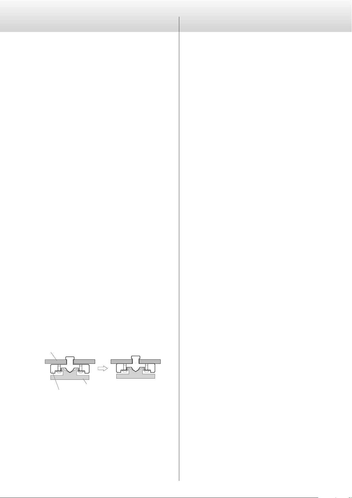
Note about power supply unit installation
High-precision metal pinpoint feet are attached to the bottom plate
of the power supply unit.
The pinpoint feet and their stands are loose, but when this unit is
placed in position, it is supported by these pinpoint feet, which effec-
tively disperse vibrations.
Chassis
Pinpoint foot (metal)
Foot-stand (metal)
After placement
oApply the included felt pads to the bottoms of the foot-stands to
avoid scratching the surface where this unit is placed.
7
English
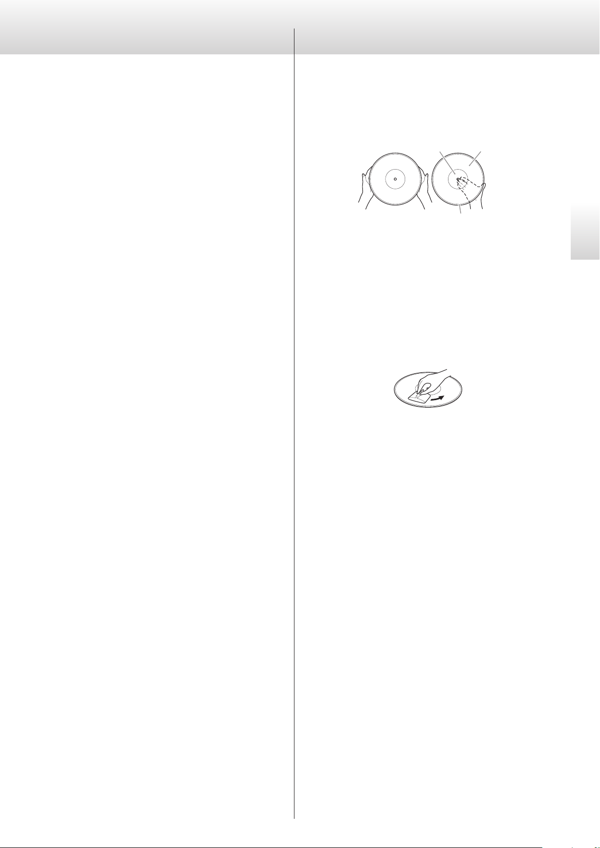
Holding records
When holding a record or removing it from its sleeve, avoid touch-
ing the grooves by holding the record by its label and edge with one
hand or by holding it by its edge with both hands.
Label Grooves
Outer edge
Cleaning
Fingerprints and dust on a record can cause noise and the sound
to skip, as well as damage the record itself and the stylus. Use a
commercially-available record cleaner to clean records. Do not use
thinner or anything other than a record cleaner. Such chemicals
could harm the surface of the record.
When using a record cleaner, wipe the surface of the record in a cir-
cular motion, following the grooves.
Precautions for use
Do not leave records in places that are exposed to direct sunlight or
are very hot or very humid. Leaving a record in such a condition for a
long time could result in warping, mold growth or other damage.
Do not stack multiple records or place heavy objects on top of them.
Do not leave records at an angle for long amounts of time, either.
Doing so could result in warping or other damage.
Do not allow hard objects to directly touch the audio grooves. Doing
so could cause scratches.
After you finish playing a record, always put it back into its sleeve
for storage. Leaving a record unprotected could result in warping or
scratching.
Do not use cracked records.
Handling recordsMaintenance
Use a soft dry cloth to wipe the surfaces of the units clean.
For stubborn smudges, use a damp cloth that has been thoroughly
wrung out to remove excess moisture.
oNever spray liquid directly on these units.
oDo not wipe with chemical cleaning cloths, thinner or other
chemical agents. Doing so could damage the surfaces of the units.
oAvoid allowing rubber or plastic materials to touch the units for
long periods of time because they could damage the cabinets.
V
For your safety, disconnect the power cord from
the outlet before cleaning.
8
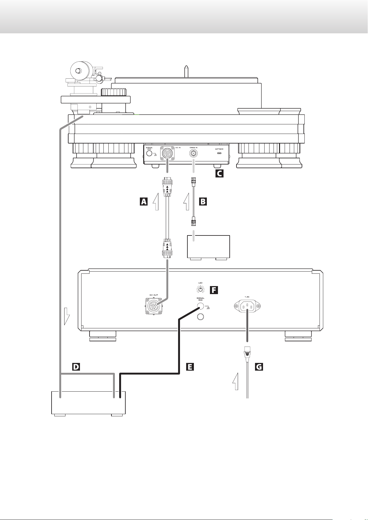
Connections
Phono amplifier or amplifier
GND
Included power cord
Device that outputs
clock signal
(GrandiosoG1X, etc.)
10MHz OUT
Phono cable
Power supply unit
Main unit
Phono input
c
wall outlet

9
English
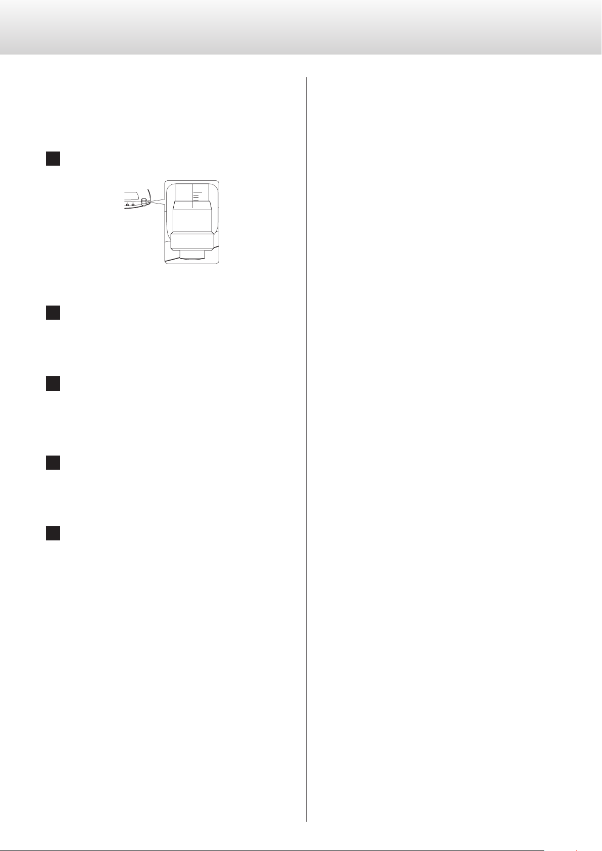
A DC power input/output connectors (DC IN/DC OUT)
Use the included DC power cord to connect the DC power input
(DC IN) connector of the main unit with the DC power output
(DC OUT) connector of the power supply unit.
DC OUT eDC IN
oThe power cord connected to the AC inlet should always be
unplugged from an outlet before the DC power cord is con-
nected or disconnected.
oThe DC power cord has arrows printed on it. Connect it so
that the arrows point in the direction shown in the illustration
on page8.
Check the orientation of the indentations, protrusions and
arrows of the DC power cord and hold it by its plug. Align
the marks on the plug to the connector and insert it. Turn the
ring clockwise to lock it. Reverse these procedures to discon-
nect it. When connecting or disconnecting the cord, do not
angle or wiggle the plug.
oBe careful not to pinch your fingers in the ring when con-
necting or disconnecting the DC power cord.
Connector
Align the indentations and pro-
trusions when connecting.
Turn the ring clockwise to lock it.
Plug
VNever connect this to anything other than a
GrandiosoT1 main unit.
Doing so could cause damage.
B 10MHz IN clock connector
Use this to input 10MHz clock synchronization signals.
To use clock synchronization, connect the clock output connec-
tor of the device outputting the clock signal to the 10MHz IN
clock connector on this unit. Then, set the external clock (CLK>)
setting to IN (page22).
Use a commercially-available BNC coaxial cable for
connection.
oBNC coaxial cables with 50Ω or 75Ω impedance can be used.
C SOFTWARE maintenance port
This is used for maintenance. Do not connect anything to this
port unless instructed to do so by our service department.
D Phono cable
Use a commercially-available cable for connection.
Always connect the grounding wire of the phono cable to the
phono amplifier. Failure to connect it could result in ground hum
(audible noise) from the power supply.
E SIGNAL GND grounding terminal
The audio quality might be improved by connecting this
grounding terminal to an amplifier or other device that is con-
nected to the GrandiosoT1.
oThis is not a safety grounding terminal.
If noise from speakers is conspicuous
If a ground wire is connected to the grounding terminal of the
GrandiosoT1, disconnecting it could reduce noise. Use the
method (connected/disconnected) that has the least noise.
F LED brightness adjustment knob
Use this to adjust the brightness of the power indicator.
G AC power inlet (~IN)
Connect the included AC power cord to this AC inlet. After com-
pleting all other connections, plug the power plug into a power
outlet.
VUse only a genuine ESOTERIC power cord. Use of
other power cords could result in fire or electric
shock.
VDisconnect the power plug from the outlet if you
will not use the GrandiosoT1 for a long time.
10
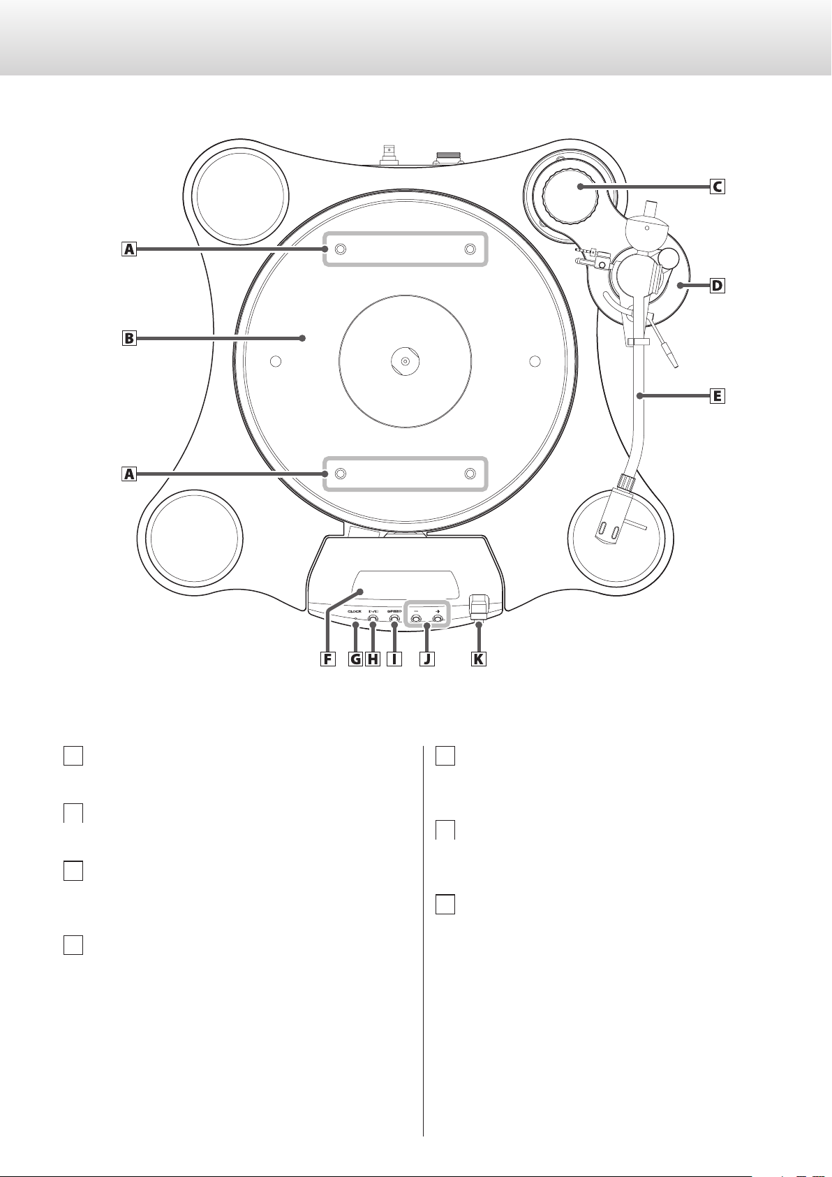
Main unit parts and functions
A Screw holes for handle attachment
B Platter
C Arm base attachment thumbscrew
This is not included with armless models.
D Arm base
This is not included with armless models.
If an armless model is purchased, an arm base kit will also be
necessary. We accept custom orders for arm base kits that sup-
port various types of arms.
E Tonearm (TA-9D)
Prepare one for use with an armless model.
F Display
This shows various information.
G CLOCK indicator
This shows the clock synchronization status.
This indicator blinks during clock synchronization and lights
when synchronization completes.

11
English
H Play/stop (t/8) button
This starts and stops platter rotation.
Press this when the unit is off to turn it on.
Press and hold this (for about 5seconds) when the unit is on to
turn it off.
Press this when in setting mode to end making settings and
return the display to its usual state (page22).
I SPEED button
Select the rotation speed indicated on the record to be played.
Press this to switch between 33 1/3 and 45 RPM.
Press and hold this to enter setting mode (page22).
Use this to change setting items when in setting mode.
Press and hold this to end making settings.
J Rotation speed adjustment (−/+) buttons
Use these to adjust the platter rotation speed precisely.
The speed can be adjusted ±12.0% in 0.1% increments.
Use these to change setting values when in setting mode
(page22).
K Micrometer adjustment knob
Use this to adjust the space between the motor and the platter.

12
Power supply unit parts and functions
L POWER button
Press this to turn the GrandiosoT1 on and off.
Turn it off when not using it.
M Power indicator
This lights when the GrandiosoT1 is on.

13
English
Installation
This product is provided in one set of three packages.
Package 1
Base unit Arm base
oThis is not included with arm-
less models.
Spacer block Unit protective covers
(Pre-attached to base unit)
Package 2
Platter Handles
Motor unit Height confirmation gauge
(in accessory box)
Installation rail (L) Installation rail (R)
Package 3
Power supply unit Tonearm (TA-9D)*
*A tonearm is not included with armless models.
VThe base unit weighs 17kg (37 1/2lb), the platter
weighs 19kg (42lb), the motor unit weighs 9kg
(19 7/8lb) and the power supply unit weighs 18kg
(39 3/4lb). This equipment is very heavy, so work
with two or more people and take care to avoid
injury when opening the packages and moving the
parts.
1 Install the base unit on a at and level surface.
oBe mindful of the weight-bearing capacity of the installation
location.
oAdjust the position of the base unit precisely at this stage. The
following steps must be conducted with the base unit in a
fixed position.
2 Attach the handles to the platter.
oAfter loosely screwing the handles all the way in, unscrew
them slightly so that they are in a position that is easy to lift.
Do not install the handles tightly.
oBe careful when handling the heavy platter, which weighs
19kg (42lb).
Continued on the next page e
14
Installation (continued)
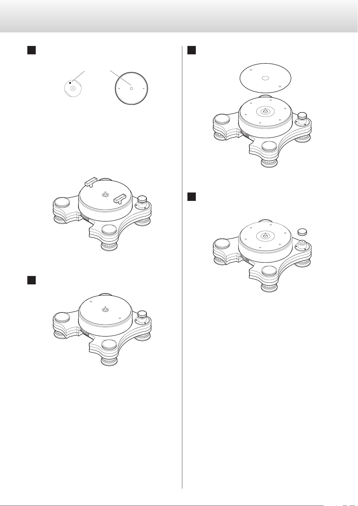
3 Attach the platter to the base unit.
Alignment marks
u
Center shaft Platter
Marks have been placed in the positions that enable ideal pre-
cision for assembly of the center shaft and the platter. Adjust
the orientation of the platter so that the marks align when it is
installed.
oThe center shaft cannot be turned before the platter is installed.
oWhen installing the platter, put it on slowly and be careful not
to catch any fingers between the platter and the base plate.
4 Remove the handles from the platter.
5 Remove the platter protection sheet.
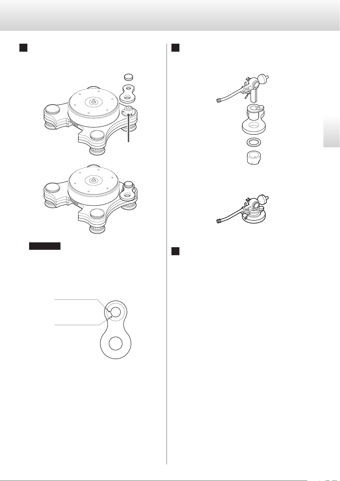
6 Remove the arm base attachment thumbscrew
from the base unit.
15
English
7 Attach the arm base to the base unit.
Align a positioning indentation on the underside of the arm
base with the pin on the arm base post when installing it.
ATTENTION
oTo ensure level installation, be sure to install the arm before
adjusting the height of the base unit.
oThe arm base has 2 positioning indentations. Choose the
indentation according to the length of the arm.
9-inch arm positioning
indentation
12-inch arm
positioning indentation
The TA-9D tonearm is a 9-inch arm.
oWhen placed correctly, the tops of the arm base and the
arm base post should be almost the same height. If there is
a large height difference between the arm base and the arm
base post, the positioning indentation and the pin might not
be aligned. Try installing the arm base again.
Arm base post
8 Attach the tonearm to the arm base.
Refer to the owner’s manual included with the tonearm and
install it.
Tonearm installed in the arm base
9 Attach the headshell to the tonearm.
Continued on the next page e

16
10
Adjust the heights of the base unit feet so that
the platter is level.
In order to confirm the level placement of the turntable, we rec-
ommend using, for example, a commercially-available turntable
leveling device.
Increase base unit
height
Decrease base unit
height
Turn this part
ATTENTION
oPress down on the four corners of the base unit to confirm
that the weight is distributed evenly on the four feet. If one of
the feet is wobbly, adjust its height.
oTo avoid lowering the feet too much, adjust the height within
a range that allows the included height confirmation gauge
to fit all four sides of the base unit. This will enable the motor
unit to be placed under the base unit in a later step.
Height confirmation
gauge
11
Conrm that the protective covers are attached
to the base unit at the locations shown by the
arrows.
Reattach them if they were removed during installation.
12
Place the spacer block on the base unit so that it
touches the platter as shown in the illustration.
oAttach the spacer block with the proper up-down orientation.
13
Place the installation rails between the base
unit feet.
oThe installation rail that has 2 screw holes is for the right side.
2
screw holes
Installation (continued)

17
English
Place the installation rails so that they touch the base unit feet
at the places shown by the arrows. (The base unit is shown by
dashed lines for this explanation.)
14
Remove the transportation screws from the
bottom of the motor unit.
oThe removed screws will be necessary for transportation, so
save them so they will not be lost. After installation is com-
plete, attach the transportation screws to the screw holes in
the installation rail (R).
15
Set the micrometer value for the motor unit to 3.
0
0
16
Following the installation rails, insert the motor
unit.
Insert the motor unit until there are no spaces between it, the
platter and the spacer block.
oWhen inserting the motor unit, be careful not to let it touch
the base unit.
oIf the motor unit and the base unit touch, use the height con-
firmation gauge and adjust the base unit height.
Continued on the next page e

18
17
Place the power supply unit near the base unit
and connect it to the motor unit with the DC
power cord (page8).
When using a clock generator, connect it to the 10MHz IN
connector.
18
Use a phono cable (sold separately) to connect
the tonearm with a phono amp or the phono
input of an amp.
Use a commercially-available phono cable for connection.
oAlways connect the grounding wire of the phono cable, too.
19
While preventing the motor unit from moving
by, for example, holding it down by hand, pull
out the installation rails.
oIf the motor unit is moved while pulling out the installation
rails, put the rails back into their original positions. Insert the
motor unit until there are no spaces between it, the platter
and the spacer block. Then, pull out the installation rails.
20
Remove the spacer block from the platter.
Installation (continued)
21
Remove the protective covers attached to the
base unit at the locations shown by the arrows.
22
Place the turntable mat on the platter.
23
Adjust the tonearm.
oRefer to the owner’s manual for the tonearm being used and
adjust it.
oAfter completing all connections, plug the power plug into a
power outlet.
ATTENTION
Save the tools used for installation because they will be needed
when relocating the equipment.
Adjusting the distance between the plat-
ter and the magnetic driver
Adjusting the distance between the platter and the magnetic driver
will change the sound when a record is playing.
The default position is 3.
The adjustment range is 2–3.
Set the micrometer adjustment knob to the desired position.
0
0
Increase distanceReduce distance

19
English
Place the installation rails so that they touch the base unit feet
at the places shown by the arrows. (The base unit is shown by
dashed lines for this explanation.)
4 Remove the cables connected to the motor unit
and tonearm.
5 Pull out the motor unit.
6 Remove the installation rails, spacer block and
protective covers.
Removing the motor unit
1 Attach the protective covers to the base unit at
the locations shown by the arrows.
2 Place the spacer block between the motor unit
and the platter as shown in the illustration.
3 Place the installation rails between the base
unit feet.
oRemove the transportation screws from the installation rails if
they have been attached.
20
Resetting the motor unit to its default
position
If the motor unit has moved because of an earthquake, for example,
follow the procedures below to fix its position.
1 Set the micrometer value for the motor unit to 3.
0
0
2 Conduct steps 1–3 in “Removing the motor
unit” on page19.
3 Adjust the motor unit position.
Push in the motor unit until there are no spaces between it, the
platter and the spacer block.
4 Follow the installation procedures from step19
(on page18) to remove the tools.
5 Set the micrometer value for the motor unit as
desired.
Installation (continued)
Table of contents
Languages:
Other Esoteric Turntable manuals


