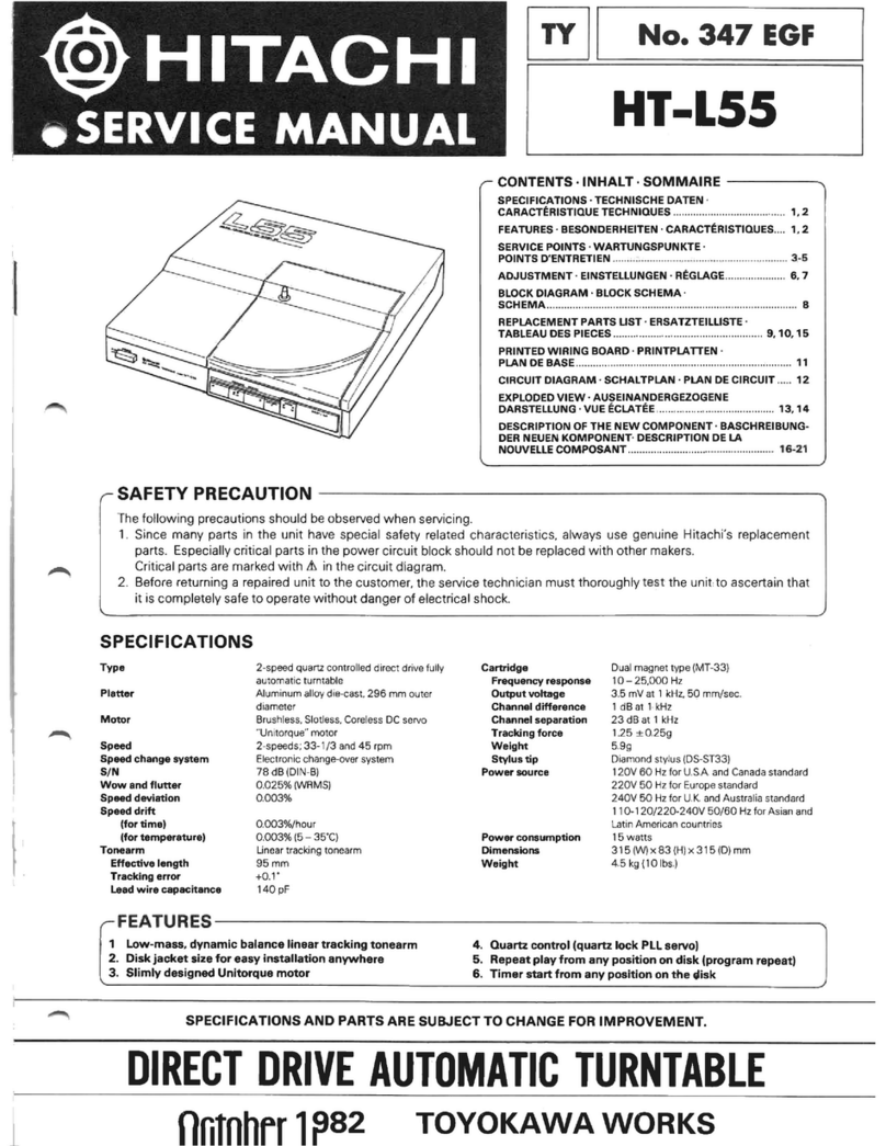
Nippon Columbia Denon DP-11F Series User manual

DENON
SERVICE MANUAL
FULLY AUTOMATIC
DIRECT DRIVE TURNTABLE SYSTEM
MODEL DP-l IF SERIES
Hr Fr Component
U.S. and Canadian models do not include cartridge.
NIPPON COLUMBIA CO., LTD.
www.hifiengine.com

TABLE OF CONTENTS
FEATURES
SPECIFICATIONS. .....
BLOCK DIAGRAM
PART NAMES AND FUNCTION
EXPLANATION OF THE MICROPROCESSOR
ADJUSTMENT METHOD ....
PARTS LIST OF EXPLODED VIEW
EXPLODED VIEW OF MAIN PARTS
SCHEMATIC DIAGRAM
PRINTED CIRCUIT BOARD
CONNECTIONS OF P.C. BOARD
PARTS LIST OF P.C. BOARD.. ..
1
2
3
4
5'8
I -10
11
12
13
14
15
16
WARNING:
1. Component parts
Parts marked with A and/or shading in this service manual have special characteristics important to
safety. Be sure to use the specified parts for replacement.
2. Leakage current
Before returning the appliance to customer, test the leakage current when the power plug is connected.
Use a calibrated (with an error of not more than 5%) leakage current tester and measure the leakage
current from any exposed metal to the earth ground. Reverse the power plug polarity and test the above
again.
Any current measured MUST NOT EXCEED 0.5 miliamps. Corrective measure must be taken if it
exceeds the limit.
Silent, fully automatic operations with the use
of a microprocessor controlled contactless servo
tonearm.
An innovative microprocessor controlled, contactless servo
tonearm ensures safe, easy to use automatic operations with
little loss in sound quality.
Low mass straight arm
This arm is fully capable of maximizing the performance of
high compliance cartridges with outstanding tracing ability.
Even with the newest, high grade records, its tracing ability
is outstanding.
DENON Quartz
The turntable speed is controlled by the "DENON Ouartz"
which is the combination of the "High Precision Magnetic
Pulse Detection Method". the most sophisticated method
of FG detection, and the "Ouartz Lock".
-1-
www.hifiengine.com

SPECIFICATIONS
Phonomotor section
Drive system: Servo controlled direct drive
Turntable speeds: 33-1/3,45 rpm
Wow & flutter: Below 0.02% wrms (servo system)
Below 0.037o wrms (JlS)
S/N ratio: Over 75 dB (D|N-B)
Rise time: Normal speed within 2 seconds (at 33-1 /3 rpm)
Platter: Aluminum die-cast;300 mm diameter
Motor: Linear drive motor
Speed control system: Speed servo by frequency detection, phase servo control
Speed deviation: Below 0.002%
Load characteristics: 0% (gO g stylus force; outermost groove)
General
Power supply: 50-60 Hz, Voltage is shown on rating label
Power consumption: 7 W
Dimensions: 100 x 365 x 335 mm (H x W x D)
Weight: Approximately 5 kg
Tonearm section
Arm type: Dynamically balance, semi-integrated straight arm
Effegtive length: 22O mm
Overhang: 16 mm
Tracking error: Within 3o
Automatic mechanism: Electronically controlled, fully automatic
Adjustable stylus force range: 0-3.0 g (1 scale=0.1 g)
Suitable cartridge weight range: Approximately 4.0-6.0 g (including screws, nuts)
Cartridge section (Only for those models with attached cartridge)
DL-60
Type: Moving magnet (MM)
Output voltage: 2.5 mV
Frequency response: 20-30 kHz
Stylus force: 1.810.3 g
Above specifications and outward appearance may be altered in future for improvement.
U.S. and Canadian models do not include cartridge.
-2-
www.hifiengine.com

Lock i
BLOCK DIAGRAM
Memorize
Reference voltage
F/V output
Start/stop command
ndication
/+* Rotation
control Power
amplifier
Speed selector
(33/451 o
Size sel ector
(30/1 7) o
Reference voltage
Memorize
Memorize
Memorize Compare/
amplify
Stop. cbntrol
Speed detection
Anti skate command
Anti skate.voltage
Rotation Power
control amPlifier
Power
amplif ier
Mid-point detection
Phonomotor
Vertical mot(
(Lifter motor
!c
o
E
E
o
o
c
3
o
E
l
E
il;l
Compare/
amplify Horizontal mol
Rotational speed detection
Magnetic polarity
dq!q9!',on _ ____?,
Magnetic polarity
detection
Motor-control
m icroprocessor
tR3T02
17130 Position
detebtion Reference voltage
Arm control
microprocessor
tR3TO3
Accela ration output
I
!o
o
o
E
c
o
N
'o
r
Rest/end detection
Speed detection
-3-
Note: -Ep inai"rt"s an analog switch
www.hifiengine.com

PART NAMES AND FUNCTION
Dust cover
Balance weight
Tonearm
REPEAT (Repeat switch)
When playing the records repeatedly, switch it on
(lamp lit).
@ eowen (Power switch)
This switch turns the power supply on (^l and off
(f ). When turning the power off, always return the
tonearm to the arm rest and hold it in place with the
clamp.
@ SlZe (Record size selector switchl
Set to the size of record to be played.
30 cm records
17 cm records
@ SfeeO (Speed selector switch)
Set to the desired record speed.
33-1/3 rpm records . . "33" (lamp lit)
4S rpm records . . . . "45" (lamp lit)
@ LOCK (Lock indicator)
When the power is turned on, the lamp will light up.
During play. the lamp will flicker until the proper
turntable speed is reached. Once the proper speed
is obtained, the lamp will, again. stay lit.
"30" (lamp lit)
"17" (lamp lit)
@ ARM LTFTER (Arm tifterswitch)
This switch is used to raise and lower the arm during
play or when playing the records manually. The lamp
is lit when arm is up.
START (Start switchl
Press this switch when starting the records auto-
matically.
@ STOP (Stop switch)
Press this switch when stopping the record during
play.
@ STYLUS FORCE (stytus force adjustment knob)
\
\\
-4-
This knob is used to adjust the stylus force.
www.hifiengine.com

EXPLANATION OF THE MICROPROCESSOR
. Motor Control lC . . . lR3T02 (at standard
revolution of 33 rpm)
The numbers on the left hand side indicates the terminal
number.
2. 4.5MHz OSC
3. 4.5MHz OSC
rpm selector
H: 45 rpm
L: 33 rpm
power source input
Vcc: 5V +0.5V
FG I bypass terminal
EG =%Ycc
FG I lowPass termini
FG I inverse input
The gain set element is connected.
E9l%Ycc
FG I non-inverse input
10mVpp - 1OOmVPP
E10 = %Ycc
ground terminal
F/V output
slower than normal revolution: 2 - 4.5V
normal revolution: i 2V
faster than normal revolution: O - 2V
9.
10.
14.
15.
4.
5.
6.
7.
16. r/v hold terminal
sJnre as terminal 15
17. F/V triangular wave
slorvtr than rtornral revolution
l_ i7. .1.tj/nLs
-l
ta1/1-I,,,
__I- >2v
normal revolution
faster than normal revolution
t I ; l.ttrnS
l*.1
t/v/1 A
ItllT-::\
I
v
8. FG I outPut
t l 7' l.8tt? S
r1 - --r--'
i t: r z
,t
lowpass terminal
t,/2yct, 2-1.5v
-5-
?\/
www.hifiengine.com

18. timing pulse width-set terminal
E18 = 0.6V
19. PD triangular wave
26. START/STOP terminat
H + START
L -+ STOP
28. Lock indicator
during lock (LED tit dimty)
69HZ
+4V
stop.. ... (LEDtit)
during transition . . (LED flashes)
+4v
.r 4.5rn s.
JLTL
20. sample pulse monitor.terminal
-:J! {_s
*lF ;
:'0.6 v
advance 0
21 PD hold terminal
slowphase:2-4V
normal phase: = 2V
advancedphase:1 -3V
22. PD output
same as terminal 21
Lock detector time set terminal
during lock: 0.6V
lock disengaged:0V
Revolution detector
during revolution: :--'....-,".-I + 4V
stop: 0V
Fou
. o.4ss , 2.2H2
m
23.
el
*':
25.
- 6,-
www.hifiengine.com

o Arm Control lC lR3T03
The numbers on the left side indicates the terminal number
of the lR3T03.
1. Accelaration inPut
Except for the matching range of the lead-in detector
(E7 < I t0.6V | ), it will recognize the situation and control
the accelaration during automatic tonearm operation.
2. Accelaration output
rt 5l tz.szv t0.1v I . . . open (will not control the ac-
celaration within the match-
ing range)
er 2lrz.sv10.1v | . . . . E2=t3.95V
-3.95V: will accelarate toward the inside from rest'
+3.95V: will accelarate toward rest from the inside'
3. UP/DOWN selection of the arm lifter
When E9 is H, the control output for lifting the arm will be
made at E3 = -Vcc.
When E9 is L, the control output for lowering the arm will
be made at E3 = +Vcc.
4. Detection of the rest Position
E4< -2.64V will be recognized as the arm being at rest'
5. Detection of the END Position
When E5 2 Z.Aqv, it will be recognized to be within the
END detection range.
E5 > 2.64V when the stylus tip nears the last sections of
the sound groove.
6. End control
Whithin the END detection range of 5 (above), (E5 >
2.64V}, the arm will be returned by the END control when
E6 > 0.23V.
E5 > 0.23V when the stylus tip moves into the lead-out
groove and the arm moves fast.
7. Matching input
E7 < | 10.6V lwill be recognized as the match range for
I ead-i n .
8. Drive output
Connect to GND.
9. UP control output
When the lifter is in the UP position during automatic arm
operations or when the UP signal is sent by pressing the arm
lifter button, pin 9 will be at H level.
EgH + 4V
E9L: OV
10. DOWN time constant
To ensure that the arm is lowered completely before pro-
ceeding to the next movement, a resistor between pins 9
and 10 and a capacitor on pin 10 has a preset discharge
time constant which is somewhat longer than the time
required for the arm to be lowered. Thus, when pin 9
becomes L (EgL : 0V), and the fixed amount of time
elapses. the arm will be recognized to be DOWN as soon as
E10 < 2V.
11. ANT (Anti-skating) control
When E10 < 2V, then El1 = -4V will be the control
output needed for the anti-skating to be engaged.
When E10 2 ZV, then E11 = +4V will be the control
output needed for the anti-skating to be disengaged.
12. Negative power source
Supplies -5V.
14. SUB (substratum)
To prevent any interference from the inner elements of the
LSl, the substratum terminal is connected to the unregu-
lated side of the negative power source, since it has the
lowest electric potential.
15. GND
Standard zero electric potential is the GND.
17. Return control
When the stop comrr'and is given, or when the repeat is
disengaged and the END is detected (EO > 0.23V), a con-
trol signal output (E17H > 4V) is mqde to return the arm
to rest.
E17H > 4V
E17L: release
18. Horizontal drive control
When the arm is in resting position, or when the arm
reaches the lead-in position during automatic play, and
comes into the matching range (E7 ( 1 tO.Ov | ), a control
signal output (E18H = 4V) is made to stop the horizontal
motion of the arm.
19. Initialset
This is the preparation time setting ierminal when the
power source is turned on. The resistor in the LSI and the
outer capacitor will set the charge time constant and carry
out the initial set.
-7 -
www.hifiengine.com

20. LCTD (Located) time constant
The LSI and its outer circuits will set the LCTD time
constant to improve the detection accuracy of the lead-in
position and the arm rest position.
E20H = 1.2V . A few moments after the arm reaches
the range of detection, in other words,
after the set LCTD time constant
elapses, it will become H level, where
it is memorized immediately and then
reset to the L level.
. Before and after detection, it will
become L level.
E20L = 0V
21. Turntable (T/T) Drive Control
E21L=0V . . . . . theturntablestops
E21H release . . . . theturntable rotates
(refer to the operational explanations for pin 22)
22. Turntable (T/T) Start Position
This terminal establishes the turntable start position. The
turntable will start when the arm separates from the arm
rest and pin 22 is released, under manual and auto modes.
23. Start
Will start automatically at the GND level.
24. Auto stop
Will stop automatically at the GND level.
25. Lifter
Will raise the lifter automatically at the GND level.
26. Repeat
Will engage the repeat automatically at the GND level.
27. UP SW
An UP time constant circuit is used so that when the lifter
is in the UP condition, this terminal is released and becomes
H level; and at other times, it becomes GND level.
With this unit, the arm will start to move approximately
two seconds after the UP command.
28. Positive power supply
Supplies +5V.
-8-
www.hifiengine.com

ADJUSTMENT METHOD
* Prepare a two-channel oscilloscope for the measuring
instrument.
r Adjusting the Phonomotor Section
* Measure, using the wrapping terminal number 8 of the
motor drive circuit board as the ground referent point when
adjusting the motor OP amp. voltage offset and the motor
torque.
VR2O3 (Motor torque adiustment)
VR2Ol (Motor offset adiustment)
VR202 (Motor offset adiustment)
VR204 (Motor torque adiustment)
TP203
TP2O4
Motor drive circuit board
Servo control circuit board
VR2 45rPm Lock adjustment
VR1 33rPm Lock adiustme
1. Adjusting the motor amp. offset voltage
1) Fix the tonearm to the arm rest and connect the oscil-
loscope to TP 203 and 2Q4 .
2l Rotating the turntable by hand, adjust the center of
amplitude at TP 203 1s Q 10'1V by turning VR 201 '
3) Following the preceding directions adiust to 0 t0'1V
byturningVR 2O2 forTP 2O4
2. Adjusting the motor torque
1 ) Leave the oscilloscope connections as they were for the
motor OP amp. voltage offset adjustments'
2l Take the turntable off the main body; move the tone-
arm close to the speed detection head and rotate the
phonomotor at a fast sPeed.
(Note) Be very cautious as not to damage the cartridge
during this Procedure.
3) For T.P. 2O3 , rotate VR 2O3 and adiust to
15VP-PtO.5V.
4l For T.P. 2O4, rotate VR 2O4 and adjust to
15VP-Pt0.5V.
3. Adjusting the head gap
Adjust, so that the gap between the turntable magnetic
coating surface and the detection head is 0.18 mm.
4. Lock adjustments for 45 rpm
From hereafter, the earth reference point of the measuring
instrument should be connected to T.P. 6 of the servo
control circuit board.
1) Connect the two-channel oscilloscope to T.P. 1 and
T.P. 2.
2l Set the speed selector to 45 rpm,
3) Take the arm off the arm rest and move it toward the
turntable to rotate the phonomotor.
4l Adjust VR2 so that the pulse from T.P. 1 is posi-
tioned to % the triangular wave length from f .P. 2 .
5.
1)
2l
Lock adjustments for 33 rpm
Connect the oscilloscope in the same manner as the
45 rpm lock adjustments. Set the speed selector to
33 rpm.
Adjust VR1 in the same manner as the lock adjust-
ments for 45 rpm.
aflovFPro5r
-9-
www.hifiengine.com

o Adjusting the Arm Control Section
Lead-in adiustment hole
VR5 (Stylus force adiustment)
VR3 (Horizontal offset adiustment)
1. Adjusting the horizontal OP amp. offsetvoltage
1) Fix the tonearm to the armrest and connect the oscil-
loscope to T. P. 3 .
2\ Set the lifter switch to the UP condition.
3) Turn VR3 and adjust to 0V10.01V.
2. Adjusting the lifter OP amp. offset voltagp
1) Fix the tonearm to the armrest and connect the oscil-
loscope to T. P. 4 .
2l Set the lifter switch to the DOWN condition.
3) Turn VR4 and adjust to -1V10.1V.
3. Adjusting the stylus force
1) Turn the power supply switch OFF.
2l Take the arm off the armrest. Rotate the balance
weight so that the tonearm becomes parallel to the
turntable surface when let go.
3) Return the arm to the armrest and turn the power'
supply switch ON.
4) Wait five seconds after the arm has lowered. Place the
cartridge stylus tip onto a stylus force guage and set
the stylus force adjustment knob to 1.5 g.
(Notel At this time, the stylus tip height should be
adjusted so that it is about the same height as during
play.
5) Turn VR5 and adjust, so that the stylus force guage
reads 1.5 g.
4. Adjusting the 30 cm lead-in position
1) Place a 30 cm record on the turntable and set the
record size selector switch to "30".
(Note) Keep the bottom cover closed.
Move the arm so that the stylus tip is at approximately
the 30 cm lead-in position. lnsert a small flat-headed
screwdriver into the lead-in adjustment hole; move the
arm back and forth and fit the screw driver into the
groove of the cam inside gently.
After turning the screwdriver, pull it out. Press the
start switch and adjust so that the stylus position stops
at the 30 cm lead-in position.
(Note) The 30 cm lead-in adjustments cannot be per-
formed unless the stylus tip position is approximately
in the 30 cm lead-in position. ln addition, if the screw-
driver is left inserted, the arm will not move.
5. Adjusting the 17 cm lead-in position
Adjust as necessary, such as when parts of the sensor sec-
tion have been replaced.
However, the following procedures should only be used
when a discrepancy is found for the 17 cm lead-in position,
after the 30 cm lead-in position has been adjusted.
1) Set the record size selector to 17 cm.
2l By continuously pressing the start switch, the arm will
move over and stop. At this time, check now many
millimeters, toward the inside or outside, the stylus tip
deviates from the required 17 cm lead-in position.
3) Take off the bottom cover of the cabinet and check the
adjustment scale position of the shutter. (One adjust-
ment scale corresponds to a stylus tip movement of
5 mm.)
4l Untighten the screw holding the sub shutter and place
a small screwdriver into the slot of the shutter. When
the stylus position is toward the inside, compared to
the required position, move the sub shutter toward the
right of the scale; when the stylus position is toward
the outside, move the sub shutter toward the left.
When completed, tentatively tighten the screw holding
the sub shutter.
5) After the adjustments are made, press the start switch
and check whether or not the stylus stops at the 1 7 cm
lead-in position.
6) lf the stylus stops at the required position, then tighten
the sub shutter screw.
Sub shutter
2l
3)
VR4 (Lifter of f set adiustment)
-10-
Adjustment scale sub shutter screw
www.hifiengine.com

PARTS LIST OF EXPLODED VIEW
Ref .
No. Part No. Part Name Remarks
1
2
3
4
5
6
7
8
9
10
11
12
13
14
15
'16
17
18
19
20
21
22
aa
24
25
26
27
28
29
30
31
32
33
34
35
36
37
JO
39
40
41
42
43
44
45
46
47
48
49
50
51
52
58
59
473030601 2 |
4751005004 I
I
1048066018 |
4730306038 |
1058083104 I
421A21720g1
I
I
421 8288005 J
4628023009
5298006002
1468137103
401 8059007
31585451 13
3138003109
3 1 58705005
209825 1 005
4618113000
2224468004
47 12303017
4638225004
471 1 30301 8
4751003006
4438545104
4338172004
43381 77300
476 t 003009
3158451003
34 1 8025205
2398013105
4338181008
4744102037
4248019105
441 881 5003
4698008009
2228468004
4730304014
3939041 001
222A46800a
4 7 1 3808003
4 7 1 3806003
2178062101
473030901 9
wAo1074
4620027003
2339051 0b3
2339058006
23390501 01
441 8846001
441Aa14208
39 1 8423006
47000090 1 9
2228464004
211AO24002
1 1 28085003
2033642103
2062002031
20060 1 9307
2062024006
200603 1 026
20620 1 9008
3x1 2 CBRTS (1 )
4W
INSULATOR ASS'Y
3x1 2 CBRTS (1 )
BOTTOM COVER ASS'Y
RECORDED TURN TABLE
RUBBER SHEET
BUSH I NG
45 ADAPTOR
DUST COVER ASS'Y
HINGE
INCLUDED SCREW
ARM REST
CARTRIDGE GENE ASS'Y
MAIN BODY ASS'Y
TERMINAL WIRE
SPRING PLATE
OUTPUT P.C.B
3x6 CFS
SPR I NG
3x6 CPS
3W
COLLAR
SUB SHUTTER
SHUTTER
3E RING
FRICTION WASHER
MAGNET ASS'Y
COIL ASS'Y
YOKE (A} GENE ASS'Y
3x3 SS
ADJUST CAM
ARM PLATE
INSULATER MAT
CDS P.C.B
3x8 CBRTS (1)
LED
LED P.C.B
3x25 CBS
3x2O CPTS (1 )
MOTOR ASS'Y
3x16 CBRTS (1 )
WASHER
.FUBBER BUSH
POWER TRANS
POWER TRANS
POWER TRANS
WASHER
HEAD SUPPORT
MAGNETIC HEAD
3x6 CPSW
VOLUME HOLDER P.C.B
v16V1 5K8502
VOLUME KNOB
OUTPUT CORD ASS'Y
AC CORD
AS 3P AC CORD
AC CORD WITH LABEL
AC CORD WITH PLUG
AC CORD WITH PLUG
E1,EF,EG,EA,
EK,E1
LNS1RCP (HL)
BsBW. MBNi ll
SU5305
E 1 only
EU onlv
E2,EF,EG
EA
EK
E1
EU
Ref.
No. Part No. Part Name Remarks
63
64
65
66
1 038 1 96406
1038196422
222a46A0Oa
39391 40009
2129130008
CAB INET
CABINET
LED P.C.B
LED
PUSH SWITCH
LED
STOP KNOB
START KNOB
LIFTER KNOB
REPEAT KNOB
SPEED KNOB
SIZE KNOB
2.6x1 0CPTS(1)
PUSH SWITCH
KNOB
SERVO CONTROL UNIT
CONNECTOB
BODY CASE
BALANCE WEIGHT
ADJUST SCREW
SLIDE SWITCH
MOTOR DRIVE UNIT
E 1 only
G L-9PG24
PR-5524S-1
E1 only
67
68
69
70
71
72
73
74
15
76
7l
78
79
80
81
82
83
39391 53009
1 1 381401 03
1138139101
1 1 381 381 02
1 i38137103
1 138135105
1138136104
4730205016
21 291 80003
1138134009
KU0419
3168198000
3158693104
3 1 58695005
3 1 5870900 1
21 29 1 85008
KU0420
Bemark symbols in the parts list refer to the following countries and
a reas.
EA: Australia
EK: United Kingdom
EU: U.S.A. and Canada
E 1 : Multiple voltage model
E2: European continent
EF: French
EG: German
-11-
www.hifiengine.com

Fo
.b-o
$ o.1
VI
i9;
1.,'T I
a'
g
Y
I
F=o
Ge€(
QA'o
H
v
I
i,. /
@D
f --:-t-q34)
\_=.-_/
i
F--c
.-l
W*
I
@H,
\R $-6
Br\ {!>-a
) l;-bv.
0D)
-[
luQa
1) @€D
t:
(D<-?)
id.
i )-@
l--'\ ,/
16})
frY-
#
Bra
[-
a0)
b
@otto,*totttl F-e
1^
<AD
I
\@@
\\\
\
www.hifiengine.com

SCHEMATIC DIAGRAM
DPIIF
WIRING DIAGRAM
SPEED
tt/45
Rl4 6ak
STOP
STAR'I
REPEAT
Fig I OTHER
Europeon & Austrolion Models
;.;l
-tr*"."";;-l
rLow i
-l t'rcH I
__J
tNSIDE r DARK
IIOBIZONTAL MOTOI]
LINE VOLTAGE
Multi Voltoge Models
LI FTER
UP / DOWN
RECORO
SIZE
30/t7
KU -419
Note: o Resistance shall lte 'l /4W unless oth0rwise specilied and the unit
is !).
o The unit of capacitor is tF, P rs pF unless otherwise specif red.
o Parts marked wrth j are of rmportance rr rcsllcct to the safe-
ty. use the specified type wilhout fail.
The voltage values are measured ustng the circuit tester (DC
100 k5)/v)
This circurt dra.c;ram shows the basrc circuit. lt rs subJect lo
chanqe for the pupose of improvement.
D t-t5,2A,2t,23,24 ,301 ' tS2O?6
LED2 -7,PR55245'l
a
a
a
a
The anti-skating will be turned (
after the arm starts to go DOWN.
A "match" denotes the conditio
on the edge of a 3O or 1 7cm
"30" denotes a 30cm recored I
1 7cm record.
"33" denotes the record speed
4Srpm.
approximately five seconds
where the arm is positioned
played; "17" denotes a
33 1/3rpm; "45" denotes
I R 2Ol,2O3:zSC 2236 i^ioffi^G"7
--.-t I
HD/40668P vm
016- l9 : RvO6 t2u O.22A t2 a POWER
4 TRANS
555H2{33) lC I tR3fo2 F/v
. lAl'12y votoBCo\rRoLMrcRoPRocrssoq
4/w IL JUL P/D
33/45 rc, ru1!1,9 ^_ srqqr
F/v P/O MONITOR I,{ONJTER DETECTOR STOP
MATCHING TIME
CONSTANT
START SToP oOWN T/r r/T rNrlAL sET
TIME CONSTANT START/STOP
START POSiTION
lC 2 lR3ro3
ET ARM CONTROL MTCROPROCESSOR
TURN UP DETECTOR
HORI ZONTAL
KILLER
ACCELIN END DETECT9R ANTI, ACCELOUT
9
/30:-5v i
ltz,+q.evr
R,lo 22r I
L
HORIZONTAL lC3:lV5218L vro pOrrurOrreCtrOrul
..|.4?o IyPC324C
AC t20V
A 6oHz
Conodlon A U.S.A Models
See Fig I for oiher line Voltoqe -NJtt44556
pPC78lt405H !PC7905H
-
.ro\ )o\
ltll
##
ill|l u lJ ll
ta2 132
tr I our coM our
COM IN
ac |5v/230v
6OHz/5OHz
-13-
www.hifiengine.com

PRINTED CIRCUIT BOARD
KU.419 SERVO CONTROL UNIT
<o>
KU-420 MOTOR DRIVE UNIT
I
o
I
-o
n
N
n
--l
I
1
l
'l
o L--- ------- c
www.hifiengine.com

CONNECTIONS OF P. C. BOARD
lD PU ARll
SWLUS FORCE AOJ.
P. C. B.
KU- 420
aa
i-et-.l
[:lr-l
POTVER TRANS
lP-5
TP-6
TP{
TFE
TH
TFI
fP-7
TF8
KU-4 I I
l-ocK LEo P.c.B.
www.hifiengine.com

KU-419 SERVO CONTROL UNIT
Ref. No. Part No. Part Name R emarks
SEMICONDUCTOR GROUP
tc1
tc2
tc3
tq
tc5
rc6
tc7
tc8
tc9
TR1 ,2,"1O
TR4-9
TR3
D1-15, 20
21 ,23,24,
301
Dl6-19
TH1
LEDl
LED2-7
LED8,9
cDsl ,2
CD53
2630173004
26301 74003
26301 89001
2630146002
26301 98005
2630147001
2630 1 60004
2620276005
2620092001
2710102005
27301 98002
2740038000
2760049008
2760237001
276031 1008
39391 40009
39391 53009
3939041 001
39390ss001
3939053028
tR3T02
tR3T03
M5218L
p,PC324C
NJM4556
pPC78M05H
pPC79O5H
H D1 4066BP
M53205P
2SA1 015 (Yl
25C181 5 (Yl
2SD467 (Cl
ts2076
RVO6
THERMISTER
LED
LED
LED
cDs
CDS
TD5-C210D
GL.9PG24
PR-5524S-1
LN81 RCP(H L)
10-1sKe
RESISTOR GROUP
R30
R25
R15
R17
vRl ,2
VR3-5
VR6
2452195008
2452201002
2452207006
2452223006
EP-5462H15
21 16000073
2114024002
RN14K2E332G
R N1 4K2E562G
R N1 4K2E1 O3G
R N1 4K2E473G
SOLID VOLUME
vo8PB203
v1 6V1 5KB502
Metal Jilm
3.3K0 %W
5.6Ko %W
10Ko %W
47Ka %W
Variable resistor
22Ka
20Ko
5Ka
CAPAClTOR GROUP
c33,54
c27
c32,46
c4
c11,31,36,
38-40,50,
51 ,60
c9, 10
c57
c58
c2,53
c20
c8,30,41 ,
42,45,34
c12,21 ,
35,37,49
u4
u3
c24
c61
cl.3,5,18
c16
2s3 1 055069
253 1 008003
2531004007
25s 1 008003
2531027000
253361 9005
2533657009
25s3662007
253363 7003
2544129005
2544132005
25441 36001
2542037005
2542038004
2544140000
2544044009
2544119905
2554194017
cK45B1 H1 01 K
cK45B1 h472K
cK45B1 H102K
cK45B1H472K
cK45F1 H1 042
cD45SL1 H470J
cc45sL1 H101K
cc45sL1 H271 K
cc45sL1 H271 J
CE04W1A470=
CE04WlCl00=
CE04W1Cl01 =
CE02W1 E1 02=
CEO2W1E222=
CE04W1VR7=
cE04w1 H010
CE04W1 H010=
cog3P1 H473J
Ceramic
100PF 50V
0.0047pF50v
0.001pF 50V
0.0047prF50v
0.1pF 50V
47PF sOV
100PF 50V
270PF 50V
270PF 50V
Electrolitic
47p,F 10V
10pF 16V
100pF 16V
1000pF 25V
22OOpF 25v
4.7yF 35V
l trF 50V
1pF 50V
Film
0.047pF 5OV
PARTS LIST OF P. C. BOARD
KU.42O MOTOR DRIVE UNIT
Ref. No. Part No, Part Name Remarks
OTHER PARTS GROUP
SW1-6
2228r''68008
21 291 30008
2 1 291 80003
3998025000
4178028101
4450033005
SERVO CONTROL
P.C.B.
PUSH SWITCH
PUSH SWITCH POWER SW
CRYSTAL 4.5 MHZ
HEAT SINK
WIRE CLAMP BAND
Ref . No. Part No. Part Name Remarks
SEMICONDUCTOR GROUP
1c201
TR202,204
TR201,203
H-A, H.B
TH1 ,2
26301 89001
2710105002
2730201009
27603030 1 6
276031 1 008
M521 8L
254966 (Yl
2SC2236 (Y)
H L-300C
THERMISTEB TD5{210D
RESISTOR GROUP
v203,204
v201 ,202 21 16000031
21'16000073 vo8PB1 02
vo8PB203
CAPACITOR GROUP
c202
c201
c203,204
2544034006
2544140000
255 1 076002
CEO4W1 V4R7
CE04W1 V4R7=
co93M1 H223K
OTHER PARTS GROUP
2224477002
2050 1 34908
2090047903
MOTOR DRIVE P,C.B.
IM TERMINAL PIN
0.6 JUMPER WIRE
CARTONE CASE GROUP
Ref.
No. Part No. Part Name Remarks
501822A222
5028060001
5058092023
505801 701 1
5058006006
5058023018
CARTON CASE ASS'Y
PACKING ASS'Y
LAMINATE ENVELOPE
ENVELOPE
ENVELOPE
ENVELOPE
60x260x0.03
60x100x0.03
350x640x0.05
ACCESSORIES GROUP
Ref.
No. Part No. Part Name Remarks
5298006002
421 8288005
51 18208003
5118211003
511821?0,02
3 1 58547001
3158752003
2033667007
45 ADAPTOR
RUBBER SHEET
INSTRUCTION MANUAL
INSTRUCTION MANUAL
INSTRUCTION MANUAL
SHELL ACCESORIES ASS
ALIGNMENT PLATE
PLUG ADAPTOR
E2, EA, EK,
E1, EU
EF
EG
EU
E1
. The carbon res istors rated at %W are not listed hersin.
-16-
www.hifiengine.com
Table of contents
Other Nippon Columbia Turntable manuals
