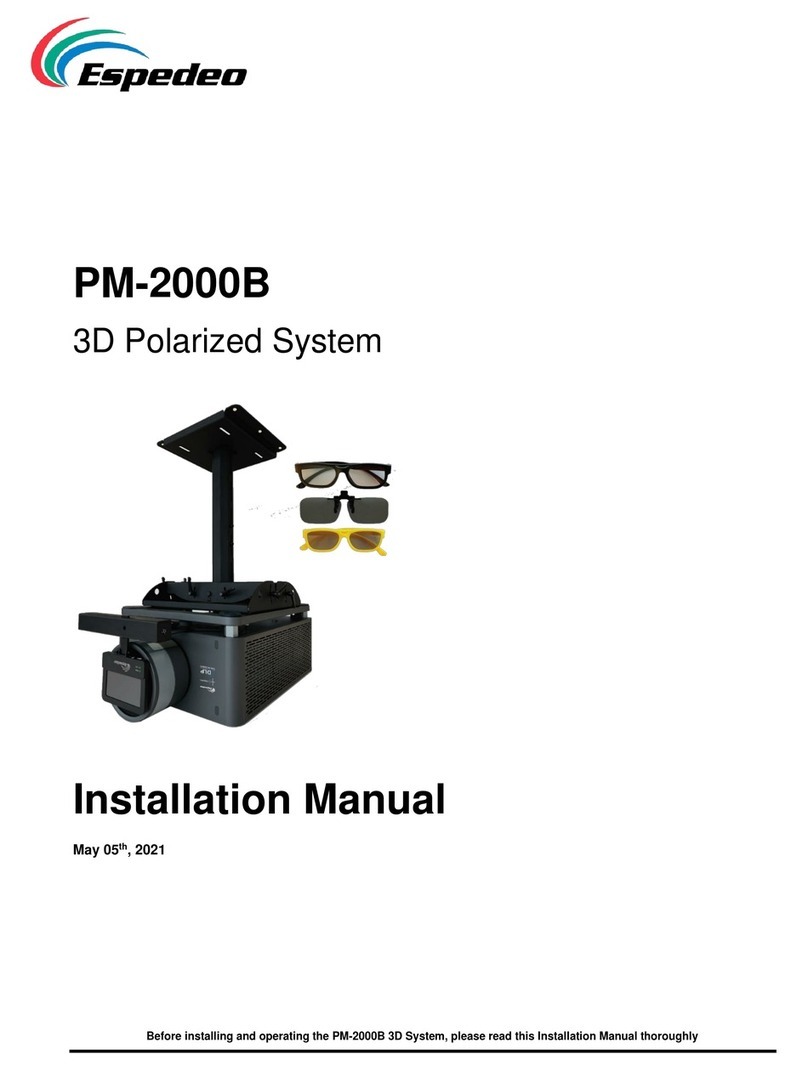
Espedeo PM-2000A User manual

PM-2000A
3D Polarized System
User Manual
October 12th, 2022
Before installing and operating the Espedeo™ PM-2000A 3D Polarized System, please read this User Manual thoroughly

- 2 -
October 12th, 2022
PM-2000A 3D Polarized System User Manual
REGULATORY NOTICES
FCC COMPLIANCE STATEMENT
This equipment has been tested and found to comply with the limits for a Class A digital device, pursuant to
Part 15 of the FCC Rules. These limits are designed to provide reasonable protection against harmful
interference when the equipment is operated in a commercial environment. This equipment generates,
uses, and can radiate radio frequency energy and, if not installed and used in accordance with the
instruction manual, may cause harmful interference to radio communications. Operation of this equipment
in a residential area is likely to cause harmful interference in which case the user will be required to correct
the interference at his own expense.
WARNING
This is a Class A product. In a domestic environment this product may cause radio interference in which
case the user may be required to take adequate measures.

- 3 -
October 12th, 2022
PM-2000A 3D Polarized System User Manual
Table of Contents
1. SYSTEM INTRODUCTION......................................................................................................1
1.1. Key Features............................................................................................................................ 1
2. SYSTEM SPECIFICATIONS......................................................................................................2
3. CORRESPONDING REQUIREMENTS FOR CINEMA..................................................................3
4. SYSTEM COMPONENTS........................................................................................................4
4.1. Polarizer.................................................................................................................................. 6
4.2. Adjustable Bracket Extension Kit..............................................................................................6
4.3. Motorized Bracket...................................................................................................................7
4.4. Bracket Support Base...............................................................................................................7
5. INSTALLATION OF THE 3D SYSTEM........................................................................................8
5.1. Installing the Motorized Bracket ..............................................................................................8
5.2. Installing the Polarizer............................................................................................................. 9
5.3. Installing the Adjustable Bracket Extension Kit ....................................................................... 10
5.4. Cable Connections for Passive 3D System............................................................................... 11
5.4.1. Alternative Power Connection when 3D Interface is not available from Projector (with power converter
and GPIO control signal)...........................................................................................................................................12
5.5. LED indicators of Passive 3D System....................................................................................... 13
5.6. Adjusting the operating position of the Polarizer for 3D Playback ........................................... 14
5.7. Adjusting the default 3D operating position of the Motorized Bracket (When adjustments
mentioned in Section 5.6 cannot be performed)................................................................................ 15
6. OPTICAL ALIGNMENT ........................................................................................................17
7. NOTES...............................................................................................................................18
7.1. Installation............................................................................................................................ 18
7.2. Routine Maintenance............................................................................................................ 18
7.3. Transportation....................................................................................................................... 18
7.4. Safety.................................................................................................................................... 19
7.5. Tips....................................................................................................................................... 19

- 1 -
October 12th, 2022
PM-2000A 3D Polarized System User Manual
- 1 -
1. System Introduction
The Espedeo™ PM-2000A is a standalone passive 3D Polarized System specially developed for digital
cinema projectors. Featuring flexible and easy installation, the system can automatically switch to the
corresponding operating position by identifying 2D and 3D signals. Equipped with specified polarized
glasses, the PM-2000A is able to present stunning and brilliant 3D images.
1.1.Key Features
▪Easy Installation
The system can be installed right in front of digital cinema projector by simply using the bracket
delivered along with the system itself.
▪Simple Connection
The entire system is simply connected by two connection cables with the digital cinema projector
and motorized bracket.
▪2D-3D Switching
The polarizer automatically identifies 2D/3D signals. It automatically moves to the front of the lens
while playing 3D images and automatically moves to the standby position when playing 2D images
or system is idle.
▪Easy Maintenance
The polarizer can be cleaned and maintained in an easy and fast manner. In addition, the polarized
glasses can be directly replaced if there are any damages of the polarized glass that affect
projection quality.

- 2 -
October 12th, 2022
PM-2000A 3D Polarized System User Manual
- 2 -
2. System Specifications
Electrical Parameters:
System power consumption
< 12W
From 3D interface
Power supply
12V DC 1A
Synchronization signal input
3D interface (15pin)
From Power converter
Power input
100 - 240V AC 60-50Hz
Power output
12V DC 1A (through the
synchronization cable)
Table 1
Optical Properties:
Projector luminance
Max. 33,000 lumens
Luminous efficiency
≥ 30% (for Espedeo™ Supra-5000 Projector)
16% ± 1% (for other DCI-compliant Projectors)
Contrast ratio
> 200:1
Cross-talk rate
< 0.5%
Response time
< 150μs
Operating temperature
0~50°C
Operating humidity
≤ 60%
Maximum screen size
18m (59ft) width
Window size
186 x 104mm
Optical type
Circular polarization
Supported Frame rates
24fps, 48fps & 60fps per eye
Table 2

- 3 -
October 12th, 2022
PM-2000A 3D Polarized System User Manual
- 3 -
3. Corresponding Requirements for Cinema
Cinema Requirements:
Polarized glasses
Espedeo™ Polarized 3D glasses
Silver screen: Luminance Gain factor
≥ 2.4
Table 3
Digital Cinema Projector Settings:
Dark time
650 - 850μs
Output Reference delay time
-120μs
Table 4

- 4 -
October 12th, 2022
PM-2000A 3D Polarized System User Manual
- 4 -
4. System Components
The PM-2000A 3D System consists of the following components:
Sr. No.
Part Description
Quantity
①
Polarizer
1 PCS.
②
Adjustable Bracket
Extension Kit
3 PCS.
③
Motorized Bracket
1 PCS.
④
Bracket Support Base
1 PCS.
⑤
DB37M/9F synchronization cable (optional with power converter)
1 PCS.
⑥
DB9M/9F motor signal cable (between bracket and polarizer)
1 PCS.
⑦
DB9F/15M synchronization cable (between projector and polarizer)
1 PCS.
⑧
Power converter (optional)
1 PCS.
⑨
Power cord (optional with power converter)
1 PCS.
Table 5

- 5 -
October 12th, 2022
PM-2000A 3D Polarized System User Manual
- 5 -
Figure 1: System Components
NOTE
When installing the 3D system, handle the equipment with care to avoid damaging the digital cinema
projector lens or the polarizer.

- 6 -
October 12th, 2022
PM-2000A 3D Polarized System User Manual
- 6 -
4.1.Polarizer
Figure 2: Polarizer
The dimensions of the polarizer are approximately 234 x 211 x 25mm and its weight is about 1.3 kg.
NOTE
The polarizer is a major optical component of the PM-2000A system. Ensure that it is handled it care
during system installation.
4.2.Adjustable Bracket Extension Kit
Length: 320mm
Length: 300mm
Length: 650mm
Figure 3: Adjustable Bracket Extension Kit
Adjustable bracket extension kit is used to connect the polarizer with the motorized bracket. It uses a
combination of aluminum rods of different lengths for easy height adjustment and makes it compatible
with various projector lens height.

- 7 -
October 12th, 2022
PM-2000A 3D Polarized System User Manual
- 7 -
4.3.Motorized Bracket
Figure 4: Motorized Bracket
▪The motorized bracket is a passive 3D system apparatus for automatic switching between
3D/2D playing.
▪Installed on top of the bracket support base, the motorized bracket connects to the polarizer
through the DB9M/9F motor signal cable. When the digital cinema projector is playing 3D movie,
the polarizer automatically moves upward to the front of the lens to polarize light paths. When
the digital cinema projector is playing 2D movie, the polarizer automatically moves downward
from the front of the lens.
▪The motorized bracket works with the adjustable bracket extension kit to adjust the position of
the polarizer.
4.4.Bracket Support Base
Figure 5: Bracket Support Base
The bracket support base is placed in front of the digital cinema projector which is used to fix the
position of motorized bracket. The height of the legs can be adjusted to fit various installations.
Moreover, two sets of screw holes are used to fix the bracket for the alternative, as shown in Figure 5.
NOTE
Please ensure that the distance between projector lens and the polarizer is within 15cm after the installation.

- 8 -
October 12th, 2022
PM-2000A 3D Polarized System User Manual
- 8 -
5. Installation of the 3D System
5.1.Installing the Motorized Bracket
Step ①: Mount the fixing blocks onto the motorized bracket with screws (M4*16mm), as shown in
Figure 6.
Step ②: Mount the motorized bracket onto the bracket support base with screws (M6*16mm), as
shown in
Figure 6.
Figure 6: Installing the Motorized Bracket

- 9 -
October 12th, 2022
PM-2000A 3D Polarized System User Manual
- 9 -
5.2.Installing the Polarizer
Step ①: Fix the polarizer onto the top of the adjustable bracket extension kit with screws (M4*16mm),
as shown in Figure 7.
Step ②: Fix the adjustable connecting trough of the adjustable bracket extension kit with screws
(M6*16mm) from the left and right sides, as shown in Figure 7.
Figure 7: Installing the Polarizer

- 10 -
October 12th, 2022
PM-2000A 3D Polarized System User Manual
- 10 -
5.3.Installing the Adjustable Bracket Extension Kit
Fix the adjustable bracket extension kit with the polarizer installed onto the motorized bracket with a
clamping block, as shown in Figure 8.
Figure 8: Installing the Adjustable Bracket Extension Kit

- 11 -
October 12th, 2022
PM-2000A 3D Polarized System User Manual
- 11 -
5.4.Cable Connections for Passive 3D System
Figure 9: Cable connections of the Passive 3D System
Connect the synchronization cable:
Connect the 15-pin end of the DB9F/15M synchronization cable to the 3D interface synchronization
signal output port on the digital cinema projector, and connect the 9-pin end to the synchronization
signal input port on the polarizer.
Connect the motor signal cable:
Connect one end of the DB9M/9F motor signal cable to the motor drive output port on the polarizer, and
connect the other end to the motor drive input port on the motorized bracket, as shown in Figure 9.

- 12 -
October 12th, 2022
PM-2000A 3D Polarized System User Manual
- 12 -
5.4.1. Alternative Power Connection when 3D Interface is not available from
Projector (with power converter and GPIO control signal)
Figure 10: Alternative power connection when 3D Interface is not available from
projector (with power converter and GPIO control signal)
Alternative power connection when 3D Interface is not available from projector:
You can connect to the passive 3D system through connecting to GPIO port on digital cinema
projector with signal converter, as shown in Figure 10.
Switch on the power supply and check the signal LEDs:
After connecting the cables, turn on the power switch of the polarizer. Activate the digital cinema
projector for 3D movie playback and check the signal LEDs on the polarizer.

- 13 -
October 12th, 2022
PM-2000A 3D Polarized System User Manual
- 13 -
5.5.LED indicators of Passive 3D System
Figure 11: LED Indicators on the Polarizer
POWER (Power LED):
Turn ON the power switch of the polarizer for power supply.
oIf the power LED is ON in green color; it indicates that the power supply has been connected.
oIf the power LED is OFF; check whether the signal cables are properly connected and whether the
digital cinema projector has been powered on.
SYNC (Synchronization signal LED):
oIf the Sync LED is ON in green color; it indicates that 3D signals are detected and a 3D movie can be
normally played.
oIf the Sync LED is OFF; it indicates that no 3D signals are detected. In this case, check whether the
synchronization cable is properly connected and whether the digital cinema projector is properly set.
L/R (Left/Right eye switching signal LED):
In case the audiences feel the depth of field is inverted inside 3D image objects; for example, which
makes the background seem to be in the front and front objects are at the back, this is because the light
phase of polarizer and 3D glass is inverted. Then we can press the L/R switch to toggle the Left/Right
eye signal for correction.

- 14 -
October 12th, 2022
PM-2000A 3D Polarized System User Manual
- 14 -
5.6.Adjusting the operating position of the Polarizer for 3D Playback
During a 3D movie playback, the polarizer automatically moves to the default/pre-set operating
position. The 3D operating position of the polarizer can be achieved by choosing aluminum rods of
suitable lengths and adjusting the height of the rod, as shown in Figure 12.
Figure 12: Adjusting the operating position of the Polarizer for 3D Playback

- 15 -
October 12th, 2022
PM-2000A 3D Polarized System User Manual
- 15 -
5.7. Adjusting the default 3D operating position of the Motorized
Bracket (When adjustments mentioned in Section 5.6 cannot be performed)
When the aluminum rods fail to enable the polarizer to be aligned to an appropriate operating position,
you would need to set the default 3D operating position of the motorized bracket, as shown in Figure 13.
Step ①: Turn OFF the power switch on the polarizer.
Step ②: Manually raise the clamping block of the motorized bracket to a height of about 300 mm from
the bracket support base, and then adjust the 3D operating position of the polarizer (so that the light
path projected out of the digital cinema projector from the lens can be completely reflected on the
polarizer and falls in its center).
Step ③: Hold the setting button and turn ON the power switch. Do not release the setting button until
the power LED is ON and the synchronization signal LED and left/right eye switching LED starts flashing.
Step ④: After the above setting is completed, the polarizer automatically moves back to the standby
position and then moves to the designated 3D operating position. Restart the system to complete the
setting operation.
If the position of 3D projection is not accurate after adjusting, you may need to adjust the aluminum
rods by loosening the screws on the clamping block to fine tune the position.
To confirm whether the installation positions are appropriate, perform the following checks:
▪During 3D movie playback, the light path projected out of the digital cinema projector just falls
within the polarizer glass frame.
▪During 2D movie playback, the passive 3D system does not block the light path projected out of the
digital cinema projector.
▪The motorized polarizer stays apart from the digital cinema projector by moving downward when
transit from 3D to 2D mode.

- 16 -
October 12th, 2022
PM-2000A 3D Polarized System User Manual
- 16 -
Figure 13: Adjusting the default 3D operating position of the Motorized Bracket

- 17 -
October 12th, 2022
PM-2000A 3D Polarized System User Manual
- 17 -
6. Optical Alignment
Load the cross-calibration pattern of the digital cinema projector and slightly adjust the top, bottom, left,
and right positions of the polarizer, so that the projected light path coincides with the cross-calibration
pattern on the projection screen.
Figure 14: Adjusting the Calibration Pattern
▪Loosen the lock screen screw on the back of hinge as indicated in Figure 14 (refer to Step ①), prior to
making any adjustments
▪Loosen screw A to turn the polarizer to adjust the top and bottom positions of the cross- calibration
pattern, note to
▪Turn the bracket support base to adjust the left and right positions of the cross-calibration pattern.
▪If the tilt level is out of above range, try to adjust the height of the legs to level the system with
reference of level meter that locate on top of polarizer during the adjustment.
▪Tighten the lock screen screw on the back of hinge, after the adjustments have been made.
Table of contents
Other Espedeo Projector Accessories manuals
Popular Projector Accessories manuals by other brands
Epson
Epson BrightLink Solo Interactive Module (IU-01 user guide
HuddleCamHD
HuddleCamHD HuddleShare user manual

Navitar
Navitar 641MCL1028 installation instructions

Navitar
Navitar 637MCZ275 installation instructions
Barco
Barco ClickShare CSE-200+ installation manual

Navitar
Navitar 570MCL070 installation instructions

