ESS ES98 2Q PRO Series User manual

2020-11-20 –TR –2.1
ES98x2Q PRO & ES98x0Q
Evaluation Board Manual
Overview of ES9842/22Q PRO and ES9840/20Q evaluation board. Including quick start guide, power
supply configuration, input/output paths, register configuration, board schematic and layout.

Contents
Quick Start Instructions ................................................................................................................................1
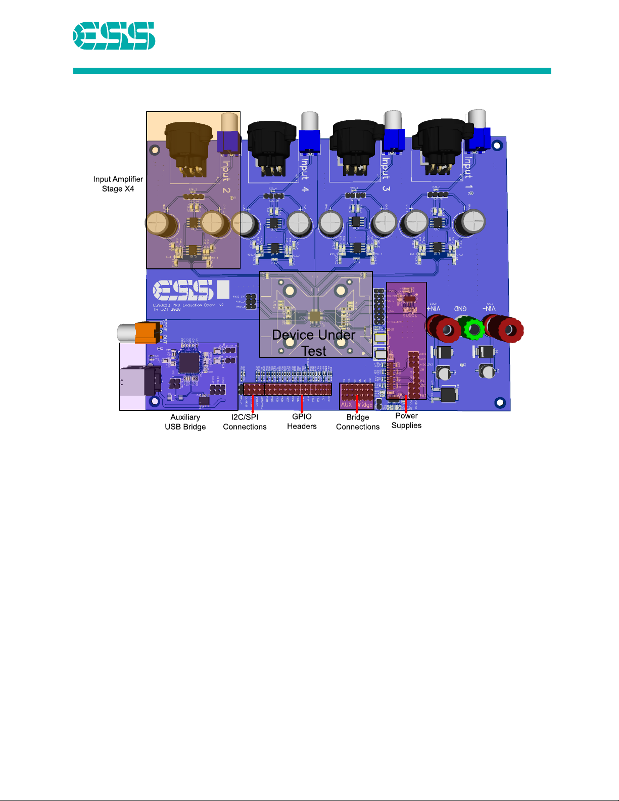
Board Overview.............................................................................................................................................2
Device Under Test.....................................................................................................................................2
Input Amplifier Stage ................................................................................................................................2
Auxiliary USB Bridge (AUX Bridge)............................................................................................................2
GPIO Headers............................................................................................................................................2
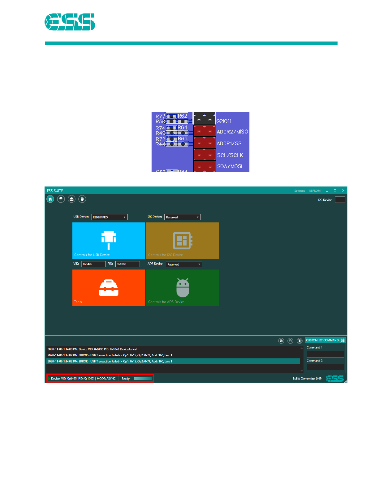
I2C/SPI Connections..................................................................................................................................3
Bridge Connections...................................................................................................................................4
Power Supplies..........................................................................................................................................4
Board Level Supplies .............................................................................................................................4
Chip Level Supplies................................................................................................................................4
Power Jumper Configuration ................................................................................................................4
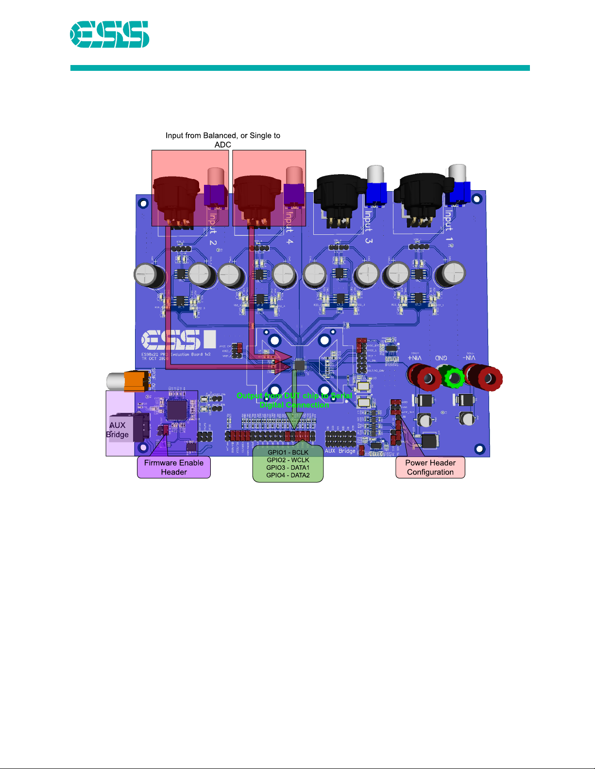
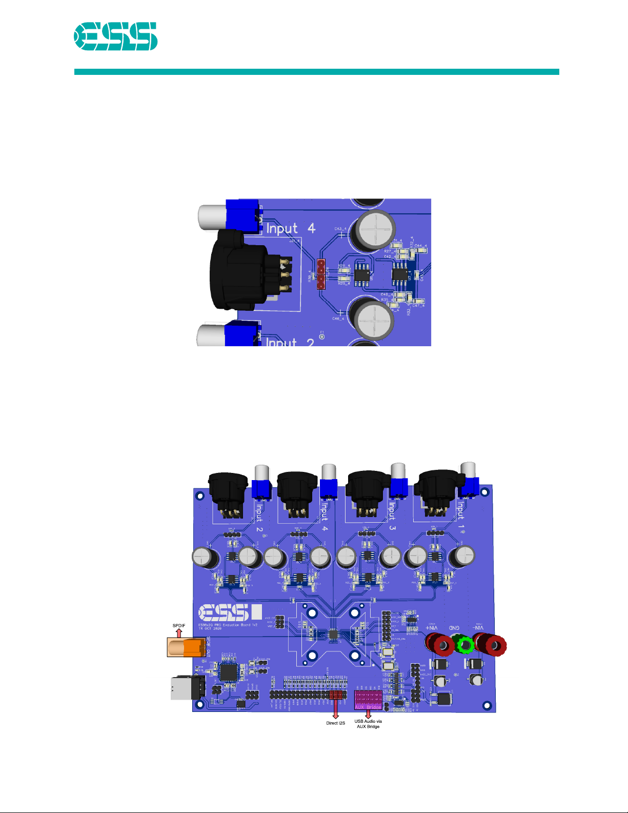
Input/Output Paths.......................................................................................................................................5
Inputs ........................................................................................................................................................5
Outputs .....................................................................................................................................................5
Register Configuration ..................................................................................................................................6
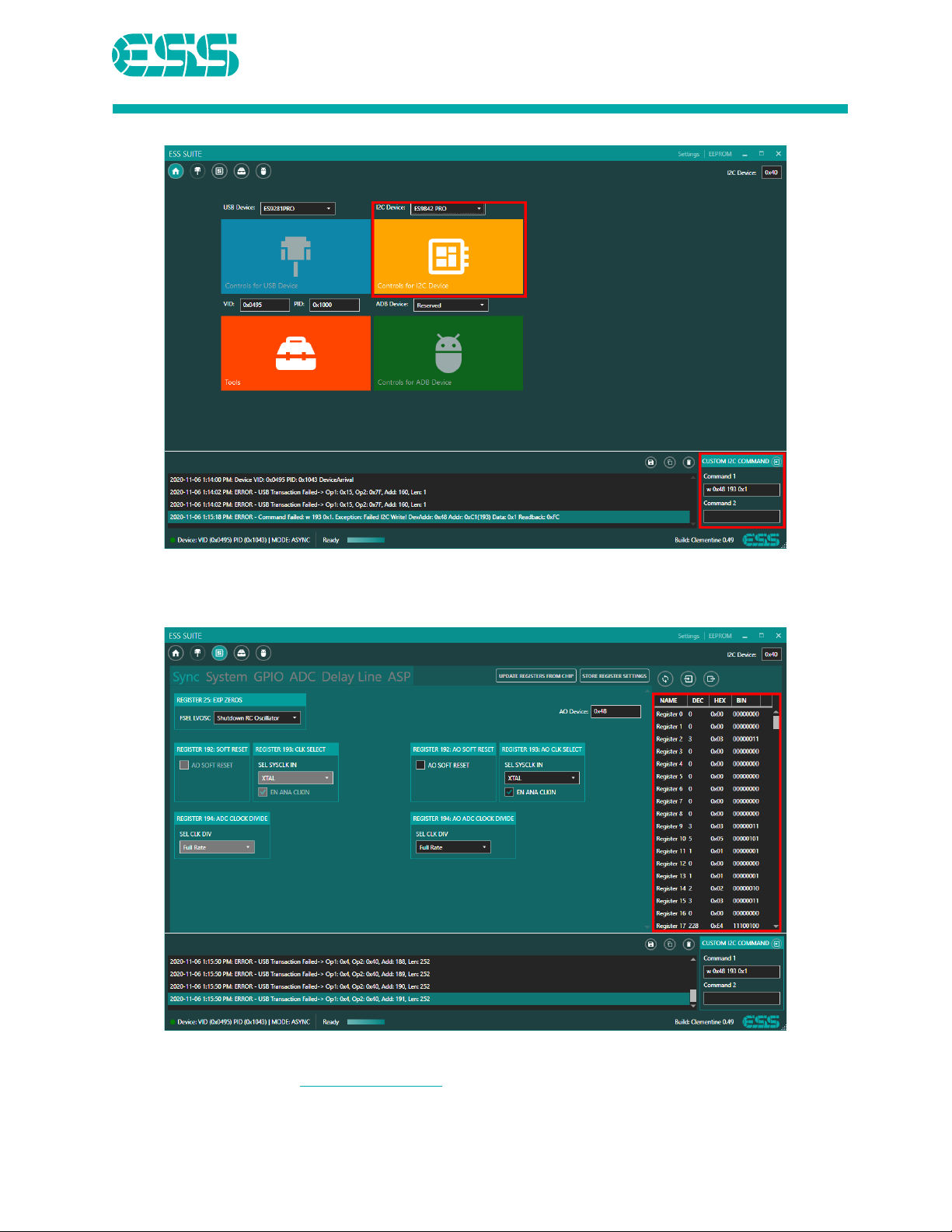
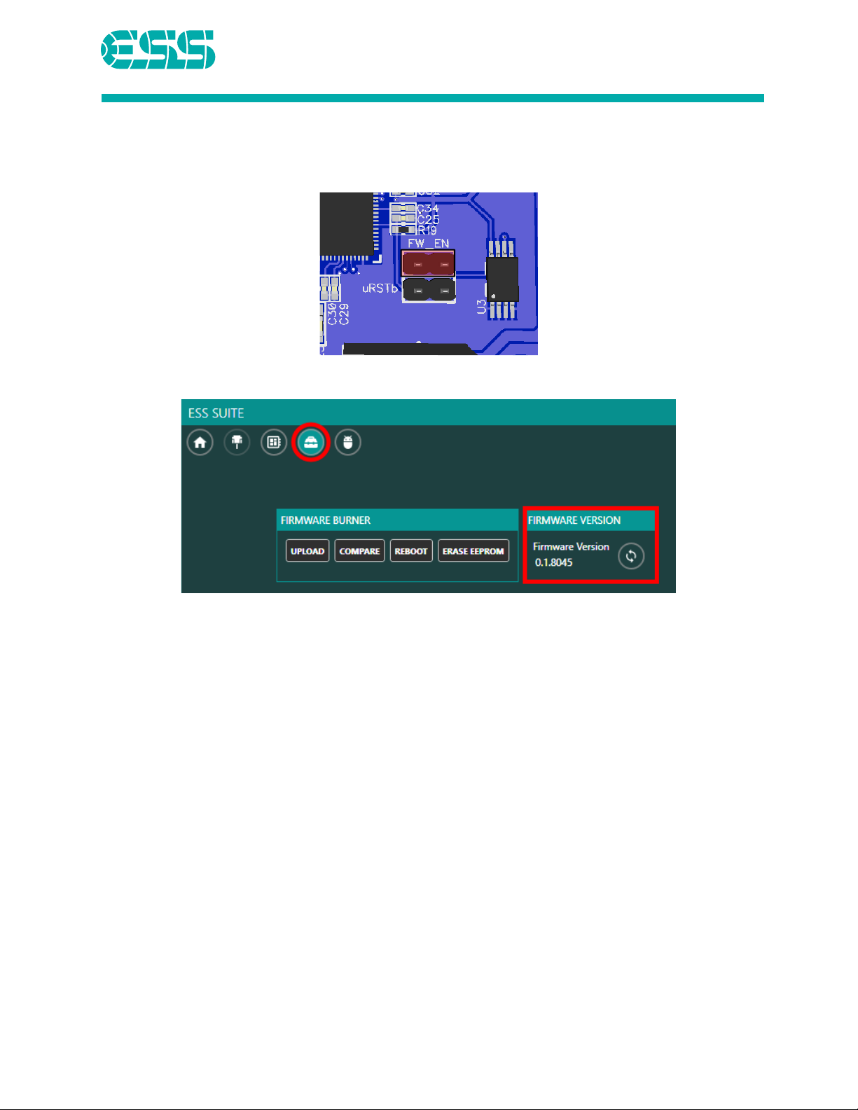
ESS GUI......................................................................................................................................................6
First Boot...............................................................................................................................................6
Automatic Register Loading..................................................................................................................8
Clocks ..........................................................................................................................................................10
Board Schematic .........................................................................................................................................12
Board Layout...............................................................................................................................................18
Revision History ..........................................................................................................................................22

ES98x2Q PRO & ES98x0Q
Evaluation Board Manual
2020-11-20 1
Quick Start Instructions
Follow these steps to quickly get started with your ES98x2Q PRO & ES98x0Q evaluation board (EVB)
1. Make sure that the headers are configured as shown.
2. Connect USB to AUX Bridge, balanced input cables and digital serial I2S cables to GPIO headers.
3. Power up the board with ±12V (do not exceed ±15V).
4. Plug in USB cable to power on AUX Bridge with its firmware enabled, which will configure the
DUT through I2C.
5. Apply signal to the balanced input.
6. Measure and decode I2S output on GPIO1 GPIO2 GPIO3 and GPIO4.

ES98x2Q PRO & ES98x0Q
Evaluation Board Manual
2020-11-20 2
Board Overview
Device Under Test
The ES98x2Q PRO & ES98x0Q ADC is the device under test (DUT).
Input Amplifier Stage
The input connectors offer the option for single ended RCA or differential XLR inputs (default).
Auxiliary USB Bridge (AUX Bridge)
The Aux USB bridge is a ES9280AQ PRO which can provide the following functions:
•ESS Suite GUI register control of DUT through I2C
•Saving register configuration for automatic loading of DUT through firmware
•Output the DUT ADC I2S audio to USB
GPIO Headers
The GPIO headers can be set in the GUI for under the GPIO heading for I2S output (set standard in
firmware) or shut down, etc.

ES98x2Q PRO & ES98x0Q
Evaluation Board Manual
2020-11-20 3
I2C/SPI Connections
ES98x2Q PRO & ES98x0Q support both I2C and SPI serial communications for register configuration.
On the EVB, the ES98x2Q PRO & ES98x0Q registers are set to be configured through I2C by the
ES9280AQ PRO.
The I2C addresses for the chip are:
Standard I2C Address
Always on I2C
ADDR1
ADDR2
0x40
0x48
L
L
0x42
0x4A
L
H
0x44
0x4C
H
L
0x46
0x4E
H
H
Note: ADDR1/ADDR2 are pulled high on the EVB, installing a jumper pulls the pin low.

ES98x2Q PRO & ES98x0Q
Evaluation Board Manual
2020-11-20 4
Bridge Connections
ADC output can be accessed through USB using the AUX Bridge by connecting the following
jumpers:
Note: USB output from the board requires firmware for the ES9280AQ PRO.
Power Supplies
Board Level Supplies
•Binding Posts +/- 12V powers:
oInput stage op-amps
oLDO and ES9311 which supplies the ES98x2Q PRO & ES98x0Q
•USB port 5V powers:
oES9280Q PRO
Chip Level Supplies
Supply
ES9842/22Q PRO
ES9840/20Q
AVCC
4.5V
3.3V
AVCC_L / AVCC_R
4.5V
3.3V
AVDD
3.3V
3.3V
Note: All AVCC supplies are provided by an ES9311 Ultra-Low Noise Regulator
Power Jumper Configuration

ES98x2Q PRO & ES98x0Q
Evaluation Board Manual
2020-11-20 5
Input/Output Paths
Inputs
There are 4 XLR and 4 RCA connectors on the board that can be used as inputs. The input stage is
designed to reach 0dBFS output at 15.75Vrms for the ES9842/22Q PRO and 11Vrms for the ES9840/20Q
The following jumpers must be installed for single ended input and removed for differential.
Outputs
Output of the ADC can be measured through:
•Direct I2S via GPIO1- GPIO6
•USB audio via the AUX Bridge (requires firmware)
•SPDIF via the orange RCA jack

ES98x2Q PRO & ES98x0Q
Evaluation Board Manual
2020-11-20 6
Register Configuration
ESS GUI
First Boot
1. The following jumpers need to be installed to connect the AUX Bridge to the DUT (I2C address
0x40):
2. Connect to USB and wait for the GUI to detect the bridge device:
3. Enter the command “w 0x48 193 0x1” in the “Custom I2C Command” window and press return

ES98x2Q PRO & ES98x0Q
Evaluation Board Manual
2020-11-20 7
4. Select ES9842 PRO from the I2C Device dropdown
5. Click on the “Controls for I2C Device” button
6. The ES98x2Q PRO & ES98x0Q is now ready to be configured either via single register changes or
S2M script:
7. If all registers show as 0xFF or 0xF0, the ES98x2Q PRO & ES98x0Q is not communicating with the
AUX Bridge. Check power configuration, SDA/SCL jumpers, “Mode” jumper, and “ADDR”
jumpers (default GUI I2C address is 0x40).

ES98x2Q PRO & ES98x0Q
Evaluation Board Manual
2020-11-20 8
Automatic Register Loading
The ESS Suite GUI can store an S2M script in the on-board EEPROM that will be loaded at boot-up.
1. Confirm that the AUX Bridge FW_EN jumper is installed:
2. Go to the “Tools” screen and confirm the firmware version is 0.1.8045

ES98x2Q PRO & ES98x0Q
Evaluation Board Manual
2020-11-20 9
3. Go to the “Controls for I2C Device” screen and press the “Store Register Settings” button
4. Select an S2M script. This script will be loaded automatically when the AUX Bridge is powered
on.
Note: The script will be loaded every time the USB is plugged in. If the board is not reset, the script
will overwrite existing registers.

ES98x2Q PRO & ES98x0Q
Evaluation Board Manual
2020-11-20 10
Clocks

ES98x2Q PRO & ES98x0Q
Evaluation Board Manual
2020-11-20 12
Board Schematic

ES98x2Q PRO & ES98x0Q
Evaluation Board Manual
2020-11-20 13

ES98x2Q PRO & ES98x0Q
Evaluation Board Manual
2020-11-20 14

ES98x2Q PRO & ES98x0Q
Evaluation Board Manual
2020-11-20 15

ES98x2Q PRO & ES98x0Q
Evaluation Board Manual
2020-11-20 16

ES98x2Q PRO & ES98x0Q
Evaluation Board Manual
2020-11-20 17

ES98x2Q PRO & ES98x0Q
Evaluation Board Manual
2020-11-20 18
Board Layout
Top Layer

ES98x2Q PRO & ES98x0Q
Evaluation Board Manual
2020-11-20 19
Inner Top Layer
This manual suits for next models
3
Table of contents
Other ESS Motherboard manuals