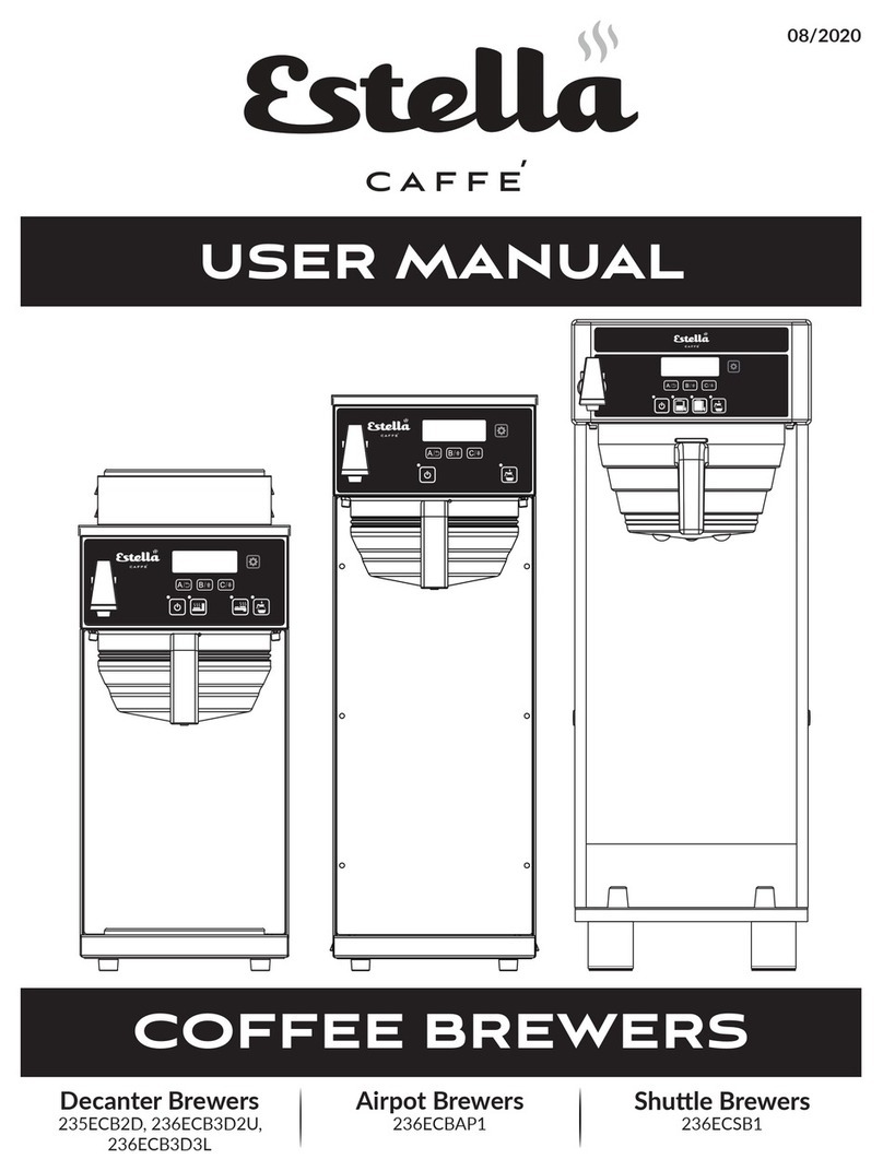
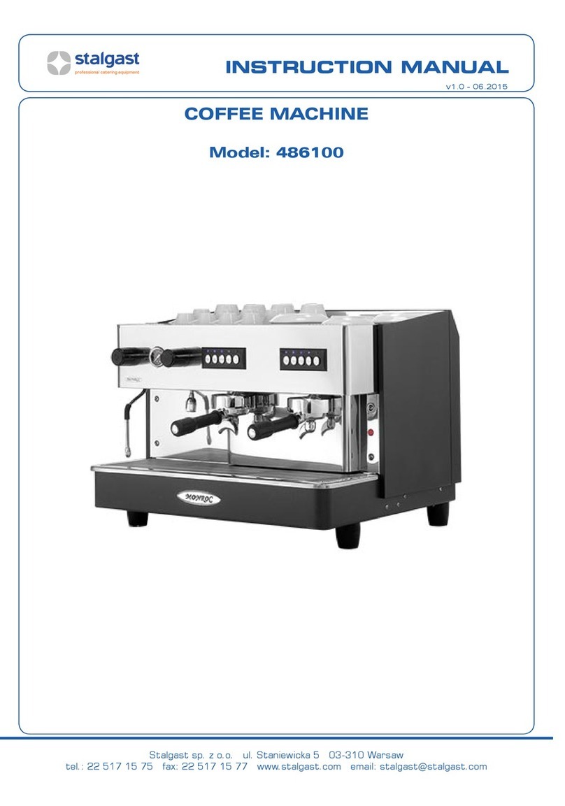
Estella 236ECEM1 User manual

This manual is for a cerfied service technician and should not be used by those who are not properly trained.
This manual cannot cover all possible condions that may occur and is not intended to be all encompassing.
You should read this manual in its enrety and the specific repair you wish to do prior to starng the repair.
This will allow you to determine if you have the correct tools, instruments, and skills to perform the procedure.
NOTICE
07/2021
#236ECEM1
One Group
#236ECEM2
Two Group
#236ECEM3
Three Group
ESPRESSO MACHINES
SERVICE MANUAL

2
Specificaঞons. . . . . . . . . . . . . . . . . . . . . . . . . . . . . . . . . . . . . . . . . . . . . . . . . . . . . . . . . . . . . . . . . . . . . . .3
Unit Specificaons
Water Input
Serial Plates
Iniঞal Setup . . . . . . . . . . . . . . . . . . . . . . . . . . . . . . . . . . . . . . . . . . . . . . . . . . . . . . . . . . . . . . . . . . . . . . . .4
Plumbing
Power Supply Wiring
Inial Starng
Programming
Preventaঞve Maintenance . . . . . . . . . . . . . . . . . . . . . . . . . . . . . . . . . . . . . . . . . . . . . . . . . . . . . . . . . . .6
End of Day Cleaning
Descaling Boiler
Troubleshooঞng . . . . . . . . . . . . . . . . . . . . . . . . . . . . . . . . . . . . . . . . . . . . . . . . . . . . . . . . . . . . . . . . . . . .8
Part Replacement . . . . . . . . . . . . . . . . . . . . . . . . . . . . . . . . . . . . . . . . . . . . . . . . . . . . . . . . . . . . . . . . . 10
Pre-Maintenance . . . . . . . . . . . . . . . . . . . . . . . . . . . . . . . . . . . . . . . . . . . . . . . . . . . . . . . . . . . . .10
Group Solenoid Valve . . . . . . . . . . . . . . . . . . . . . . . . . . . . . . . . . . . . . . . . . . . . . . . . . . . . . . . . .10
Boiler Water Level Probe . . . . . . . . . . . . . . . . . . . . . . . . . . . . . . . . . . . . . . . . . . . . . . . . . . . . . .11
Solid State Relay (SSR) . . . . . . . . . . . . . . . . . . . . . . . . . . . . . . . . . . . . . . . . . . . . . . . . . . . . . . . .12
Boiler Solenoid Valve (Fill Valve) . . . . . . . . . . . . . . . . . . . . . . . . . . . . . . . . . . . . . . . . . . . . . . . .13
Steam Pressure Switch . . . . . . . . . . . . . . . . . . . . . . . . . . . . . . . . . . . . . . . . . . . . . . . . . . . . . . . .14
Steam Pressure Switch Adjustments . . . . . . . . . . . . . . . . . . . . . . . . . . . . . . . . . . . . . . . . . . . .14
Boiler Element . . . . . . . . . . . . . . . . . . . . . . . . . . . . . . . . . . . . . . . . . . . . . . . . . . . . . . . . . . . . . . .15
Boiler Pump . . . . . . . . . . . . . . . . . . . . . . . . . . . . . . . . . . . . . . . . . . . . . . . . . . . . . . . . . . . . . . . . .16
Boiler Pump Adjustment. . . . . . . . . . . . . . . . . . . . . . . . . . . . . . . . . . . . . . . . . . . . . . . . . . . . . . .16
Boiler Flowmeter . . . . . . . . . . . . . . . . . . . . . . . . . . . . . . . . . . . . . . . . . . . . . . . . . . . . . . . . . . . . .17
Circuit Board Fuses . . . . . . . . . . . . . . . . . . . . . . . . . . . . . . . . . . . . . . . . . . . . . . . . . . . . . . . . . . .18
Circuit Board Replacement. . . . . . . . . . . . . . . . . . . . . . . . . . . . . . . . . . . . . . . . . . . . . . . . . . . . .18
Steam Wand . . . . . . . . . . . . . . . . . . . . . . . . . . . . . . . . . . . . . . . . . . . . . . . . . . . . . . . . . . . . . . . . .19
Hot Water Nozzle . . . . . . . . . . . . . . . . . . . . . . . . . . . . . . . . . . . . . . . . . . . . . . . . . . . . . . . . . . . .19
Filter Mount and Screen . . . . . . . . . . . . . . . . . . . . . . . . . . . . . . . . . . . . . . . . . . . . . . . . . . . . . . .20
Group Head Filter and Gasket . . . . . . . . . . . . . . . . . . . . . . . . . . . . . . . . . . . . . . . . . . . . . . . . . .21
Steam and Hot Water Plug. . . . . . . . . . . . . . . . . . . . . . . . . . . . . . . . . . . . . . . . . . . . . . . . . . . . .22
Gauges, Steam Pressure, and Water Pressure. . . . . . . . . . . . . . . . . . . . . . . . . . . . . . . . . . . . .23
Wiring Diagrams . . . . . . . . . . . . . . . . . . . . . . . . . . . . . . . . . . . . . . . . . . . . . . . . . . . . . . . . . . . . . . . . . . 24
236ECEM1 . . . . . . . . . . . . . . . . . . . . . . . . . . . . . . . . . . . . . . . . . . . . . . . . . . . . . . . . . . . . . . . . . .24
236ECEM2 . . . . . . . . . . . . . . . . . . . . . . . . . . . . . . . . . . . . . . . . . . . . . . . . . . . . . . . . . . . . . . . . . .25
236ECEM3 . . . . . . . . . . . . . . . . . . . . . . . . . . . . . . . . . . . . . . . . . . . . . . . . . . . . . . . . . . . . . . . . . .26
TABLE OF CONTENTS

3
Serial Plates
Water Input
236ECEM1 236ECEM2 236ECEM3
Groups 123
Boiler Capacity 6 Qt. 13 Qt. 19 Qt.
Voltage 110V 220V 220V
Waage 2000W 4700W 6500W
Width 19⁄"27⁄" 37"
Depth 21⁄"21⁄"21⁄"
Height 22⁄"22⁄"22⁄"
Weight 97 Lb. 141 Lb. 179 Lb.
Minimum Maximum
Total Dissolved Solids 50 PPM 125 PPM
Total Hardness 3 GPG 5 GPG
pH Level 6.5 7.5
NOTE: All units are labeled with model numbers,
voltage, serial number, waage, and cerficaons
on the front of this machine.
Please do not remove this label for future service.
• A water connecon is required for this unit to funcon properly.
• This machine comes hardwired with no plug.
• Qualified technicians are required for installaon of this unit.
NOTES:
SPECIFICATIONS

4
NOTE: All units must be installed per local standards in force with regards to plumbing and electrical.
For this reason, a qualified technician is required for the plumbing and electrical connecons.
NEUTRAL
(Brown Wire)
NEUTRAL
(Brown Wire)
LIVE
(Blue Wire)
LIVE
(Blue Wire)
GROUND
(Green Wire)
GROUND
(Green Wire)
USER SUPPLIED PLUG
USER SUPPLIED DISCONNECT
OR
1. Dispose of packaging properly
2. Un-coil power and water supply
3. Connect 1/2" threaded pipe connecon
to water supply (Fig. 1)
4. Install drain hose, route hose up through access hole
under unit and push onto barb fing on the side of
the drain pan cup (Fig. 2)
5. Connect other end of the drain hose
to drainage system
6. Check incoming water pressure
• Incoming water pressure cannot exceed 20 bar
or 290 psi as this will damage the pump and
internal components
• Maximum incoming water temperature cannot
exceed 158°F as this will damage the
pump and internal components
• If incoming water pressure is less than 1 bar or
15 psi, the unit will me out and must be turned
off; This will cause excessive wear and tear on
the pump and void the warranty
• User must install pressure booster for incoming
water if below 1 bar or 15 psi
Plumbing
Power Supply Wiring
Fig. 1
Fig. 2
INITIAL SETUP

5
1. Turn unit on (Fig. 3) and allow boiler to fill;
internal pump will shut offwhen full
(2-3 minute fill me)
Dispensing buons will flash sequenally
during startup, leto right
2. Watch the water level site gauge (Fig. 4)
(Green secon = good)
3. Unit will start heang and building pressure once
site gauge ball is in the green
NOTE: If green level is not reached, refer to
troubleshoong on page 11
4. Boiler pressure gauge = 1.2 bars before use (Fig. 5)
NOTE: Could take up to 30 minutes depending
on unit size; If pressure does not build, refer to
troubleshoong on page 11
1. Flip program switch up to the "ON" posion (Fig. 6)
NOTE: Right most group head buons are default
for other group(s), but can sll be changed if needed
2. Dispensing buons will light up solid blue in color
3. Press program buon so just cup size lights are on
(Fig. 7)
4. Press and hold cup size(s) buon unl desired output
is reached for each size; Program 1 cup size at a me
5. Press program buon to secure cup size
programming, this will then move to the next cup
size or press again when finished with programming
6. Flip program switch to the "OFF" posion (Fig. 6) to
return machine to operang mode
Initial Starting
Programming
Fig. 3
Fig. 6
Fig. 7
Fig. 4 Fig. 5
OFF ON

6
NOTE: To ensure the best quality, longevity, and warranty status, these units should be cleaned daily.
1. Add blind filter cap (backflush disk) to
portafilter (Part #236BFDISK)
2. Add detergent (Urnex 12-ESP20) and install
portafilter
3. Press buon 1 and 5 simultaneously to start
flushing (Fig. 8)
4. Buons 2 and 4 will light up (Fig. 9); automac
reverse flushing will start and run for 10
cleaning cycles
5. To stop the reverse flushing before 10 cycles,
press buon 3 (Fig. 10)
6. Each group head should be cleaned this way
7. Turn power switch off(Fig. 11)
8. Turn offwater supply to machine
9. Turn all steam wand knobs to open
and leave them open to release
pressure from inside boiler tank
(Fig. 12)
10.Remove drain pan and grate
11.Open drain valve (Fig. 13), red lever
should be parallel with drain line,
leave drain valve open to completely
empty the tank
12.Wipe down machine as needed to
remove leover coffee grounds
and milk
13.Disassemble portafilter by gently
prying filter cup from filter holder
14.Soak portafilter in detergent
End of Day Cleaning Fig. 8
Fig. 9
Fig. 10
Fig. 11
Fig. 13
Fig. 12
OFF ON
Reverse Flushing
NOTE: Shuমng down and draining the boiler will prolong its lifespan
PREVENTATIVE MAINTENANCE

7
1. Ensure unit is off, cooled down, and boiler
tank is empty
2. Disconnect from power supply
3. Remove 2 screws from top rear cover and
remove cover (Fig. 14)
4. Remove pressure relief valve from top of
boiler tank with 19mm wrench (Fig. 15)
5. Add water and descaling mixture to boiler
tank via pressure relief valve port unl site
gauge is in the upper half of the green secon
(Fig. 16)
6. Allow unit to soak as required by descaling
product
7. Drain and flush boiler tank with fresh water
8. Reinstall pressure relief valve and top cover
9. Cycle each group head to ensure all descaling
product is removed before use
Descaling Boiler as Needed
(Recommended every 6 months)
NOTE: Descaling the boiler will prolong its lifespan and help ensure a flavorful product
Fig. 14
Fig. 15
Fig. 16

8
PROBLEM POSSIBLE SOLUTION PAGE
Pump runs and shuts off,
but site gauge
isn't in green or is
almost in green
Make sure water supply is turned on
Make sure drain pan valve is closed
Check incoming water pressure is 1 bar (30 psi) or higher 16
Check water probe funcon 11
Check boiler solenoid 13
Replace pump 16
Replace circuit board 18
No water is being
dispensed
Make sure unit is turned on
Check that the boiler tank is full, in the green on site gauge
Check that the pressure gauge shows 1.2-1.4 bar
Ensure cup buons are programmed 5
Check if programming switch is off
Check #2 fuse on circuit board 18
Check group head solenoid 10
Check group head block if hot to the touch
Check group head supply piping if hot to the touch
Check flowmeter 17
Replace circuit board 18
Turned on power switch,
but nothing happened
Check that unit is plugged in
Check that unit was wired correctly 4
Check fuse #1 on circuit board 18
Replace circuit board 18
No steam from
steam wand
Check steam wand sprayer for clogs 22
Check water level site gauge is in green range
Check that the pressure gauge shows 1.2-1.4 bar
Check gasket plug in tap valve 22
Check pressure adjustment switch 14
Check SSR status light 12
Check boiler element 15
Replace circuit board 18
TROUBLESHOOTING

9
PROBLEM POSSIBLE SOLUTION PAGE
No water from hot
water nozzle
Check hot water nozzle for clogs 22
Check water level site gauge is in green range
Check gasket plug in tap valve 22
Check SSR status light 12
Check boiler element 15
Check pressure adjustment switch 14
Replace circuit board 18
Unit has no pressure
at gauge
Check water level site gauge is in green range
Check for steam from steam wand
Check SSR status light 12
Check that boiler element has power 15
Check pressure adjustment switch 14
Replace gauge 23
Water pump does not
stop running
Check cup drain pan valve is closed
Check water probe wiring for damage
Check water probe 11
Replace circuit board 18
Water tank is not
filling up
Check if incoming water valve is open
Check that water pump is running
Check that cup drain pan valve is closed
Check infill valve 13
Replace pump 16
Pressure gauge does not
show 1.2 - 1.4 bars
Check water level site gauge is in green range
Check pressure switch adjustment 14
Check SSR status light 12
Check that boiler element has power 15
Replace gauge 23
Water does not stop
dispensing aer cup size
buon is pressed
Check if buons were programmed 5
Check group head solenoid 10
Replace flow meter 17
Replace circuit board 18

10
1. Follow Pre-Maintenance steps on page 10
2. Remove drain pan
3. Remove center cover behind brewing group
(Fig. 20)
a. Apply pressure to either side of cover
to remove from slots
1. Turn unit off(Fig. 17)
2. Disconnect from power supply
3. Turn offwater supply
4. Open steam knob and keep open to
release all pressure inside the tank
(Fig. 18), ensure pressure gauge goes
to zero and no steam is coming from
wand
5. Remove cup drain pan by liing up
and pulling away from unit
6. Open red lever on drain valve by
making the lever parallel with the
copper drain line (Fig. 19)
7. Allow unit to cool down prior to pro-
ceeding with any maintenance inside
the unit
Follow these pre-maintenance steps before servicing your Estella Caffe Espresso Machine
Pre-Maintenance
Fig. 20
Conঞnued on Page 11
CAUTION: Components can be HOT
Fig. 17
Fig. 19
Fig. 18
OFF ON
Tes ঞng
• Audible click can be heard when turned on/off
• Ohms should read ~ 2.03 for 1 Group unit,
~0.8 for 2 and 3 group unit
• Replace valve if ohm reading is infinity
Group Solenoid Valve
Time Estimate: Approximately 20 min.
Part: #236PECEM20 for 1 group unit
#236PECEM21 for 2 and 3 group units
PART REPLACEMENT

11
Fig. 21 Fig. 22
A
BBB
Tes ঞng
• Ohmmeter should read zero ohms when touching
water and ~1.2 when not touching water
• If reading is more than 10% higher, probe needs
replaced
Probe Wiring
• Part #236PECEM6
• To check if wiring is bad, test connuity of wiring
from probe end to circuit board
b. Slide down into drain pan cup area
4. Remove phillips screw from group solenoid
valve wire plug (Fig. 21)
5. Pull wiring plug
6. Remove brass hex nut and copper tube
(Fig. 22 A)
7. Remove hex nut from boom side of
valve body
8. Coil body can now be removed from valve
and tested, if needed
9. Remove 4 socket head cap screws with
3mm hex key (Fig. 22 B)
10.Note orientaon of brass mounng flange
for reassembly
NOTE: Water port holes must be aligned
with holes during installaon
11.Reassemble by reversing steps
Fig. 23
Fig. 24
B
A
1. Follow pre-maintenance steps on page 10
2. Remove 2 screws from top rear cover (Fig. 23)
3. Carefully pull wire from water level probe (Fig. 24 A)
4. Remove probe from boiler tank (Fig. 24 B) with
19mm socket wrench, do not lose copper washer
5. Reassemble by reversing steps
6. Ensure there is no air leakage aer startup
Boiler Water Level Probe
Time Estimate: Approximately 10 min.
Part: #236PECEM17

12
Fig. 25
Fig. 26 Fig. 27
A
B
A
B
B
Solid State Relay (SSR)
Time Estimate: Approximately 20 min.
Part: #236PECEM2 for 1 and 2 group units
#236PECEM3 for 3 group unit
1. Follow pre-maintenance steps from page 10
2. Remove 2 screws from top rear cover and
remove cover (Fig. 25 A)
3. Remove 2 screws from leside cover and
remove cover (Fig. 25 B)
4. Remove clear plasc cover, pull straight off
body of SSR (Fig. 26 A)
5. Remove the 2 mounng screws from the top and
boom (Fig. 26 B)
6. Pull away from heat sink, thermal pad between
heat sink and SSR comes with replacement SSR
7. Disconnect wire terminals from old SSR,
one terminal at a me (Fig. 27)
8. Aach wires to new SSR, one terminal at a me
9. Reassemble by reversing steps
10.Ensure connecons are secure prior to
applying power to the unit
Tes ঞng
• Status Light, will illuminate when powered "on"
• On = pressure switch acvaon
• Check proper voltage from #1 to #2 and that boiler
element has voltage
• If status light is "on", but no power to boiler
element, Replace SSR

13
Fig. 28
A
B
Boiler Solenoid Valve (Fill Valve)
Time Estimate: Approximately 30 min.
Part: #236PECEM12 for 1 group unit
#236PECEM11 for 2 and 3 group units
1. Follow pre-maintenance steps from page 10
2. Remove 2 screws from top rear cover and
remove cover (Fig. 28 A)
3. Remove 2 screws from rear cover and
remove cover (Fig. 28 B)
4. Remove stainless steel braided hose from
inlet connecon (Fig. 29 A)
5. Remove brass hex nuts on copper lines
(Fig. 29 B)
6. Remove screw from wiring plug
7. Pull plug from solenoid valve
8. Remove 2 socket head cap screws from
mounng bracket, under valve (Fig. 30 A)
9. Remove valve from mounng bracket
10.Remove brass "T" fing from inlet side
of valve (Fig. 30 B)
11.Install brass "T" fing on to new valve
with thread sealant
12.Reassemble by reversing steps
Tes ঞng
• Audible click can be heard when turned on/off
• Ohms should read ~ 2.03, if coil is good
• Replace valve if ohm reading is infinity
Fig. 29
Fig. 30
A
A
B
B
B

14
Fig. 32
Fig. 34 Fig. 35
Fig. 33
A
B
Steam Pressure Switch Adjustments
Steam pressure can be adjusted, between 1.2 and 1.4 bars on pressure gauge is optimal
1. Follow pre-maintenance steps from page 10
2. Remove 2 screws from top rear cover and
remove cover (Fig. 31 A)
3. Remove 2 screws from rear cover and
remove cover (Fig. 31 B)
4. Remove copper pipe hex nut (Fig. 32 A)
5. Remove hex nut from mounng bracket
(Fig. 32 B)
6. Remove valve from mounng bracket
7. Remove wiring from old valve (Fig. 33)
8. Install wiring on new valve
9. Reassemble by reversing steps
1. Remove 2 screws from top rear cover
2. Remove yellow cover/cap (Fig. 34)
3. Adjust pressure as needed (Fig. 35)
• Adjustment range is from 0.5 to 1.4 bars
• One adjustment screw rotaon is ~ 0.1 bar
• Clockwise = Decrease
• Counter-Clockwise = Increase
4. Verify pressure on gauge
5. Replace yellow cover cap
6. Replace top rear cover
Steam Pressure Switch
Time Estimate: Approximately 30 min.
Fig. 31
A
B

15
D
D D
D
A
C
B B
B B
1. Follow pre-maintenance steps from page 10
2. Remove 2 screws from top rear cover and
remove cover (Fig. 36 A)
3. Remove 2 screws from right side cover and
remove cover (Fig. 36 B)
4. Remove grounding wire clip (Fig. 37 A) with
2.5 mm hex key
5. Remove hex nuts from element wiring
(Fig. 37 B) with 8mm socket
6. Remove copper bus bars from element
(Fig. 37 C)
NOTE: Do not lose orientaon
7. Remove 4 socket head cap screws holding
element in place (Fig. 37 D) with 5mm hex key
8. Pull element from boiler tank
9. Note gasket orientaon, replace if necessary
(Fig. 38)
NOTE: Part #236PECEM10 for all units
10.Separate gasket from heang element
11.Reassemble by reversing steps
Fig. 36
Fig. 37
C
A
B
Boiler Element
Time Estimate: Approximately 60 min.
Part: #236PECEM7 for 1 group unit
#236PECEM8 for 2 group unit
#236PECEM9 for 3 group unit
Tes ঞng
• Disconnect wires and bus bars from element
before tesng
• Part #236PECEM7 for 1 group unit should read
~9.2 ohms across each loop
• Part #236PECEM8 for 2 group unit should read
~11.5 ohms across each loop
• Part #236PECEM9 for 3 group unit should read
~ 7.3 ohms across each loop
• Element will only have power when SSR is on,
check status light on SSR
Fig. 38
NOTE: This is a good ঞme to inspect for scale build up inside of boiler

16
A
B
Boiler Pump Adjustment
If dispensing pump pressure is not within the "green" range
(8-10 bars) on the water pressure gauge, then you can
adjust the pump as required.
1. Follow pre-maintenance steps from page 10
2. Remove 2 screws from top rear cover and
remove cover (Fig. 39 A)
3. Remove 2 screws from leside cover and
remove cover (Fig. 39 B)
4. Remove 2 screws from rear cover and
remove cover (Fig. 39 C)
5. Remove stainless steel braided hoses,
nong hose locaons (Fig. 40 A)
6. Remove locking ring for pump mount to
motor (Fig. 40 B)
7. Slide pump out of motor keyed slot
8. Remove locking ring from old pump
9. Put locking ring on new pump
10.Remove adapter fings from old pump inlet
and outlet ports
11.Install adapter fing on new pump inlet and
outlet ports with thread sealant
12.Reassemble by reversing steps
1. Remove 2 screws from top rear cover and remove cover (Fig. 39 A)
2. Remove 2 screws from leside cover and remove cover (Fig. 39 B)
3. Loosen black hex nut (locking nut) (Fig. 41 A)
4. Adjust screw as required (Fig. 41 B)
Clockwise = Increase
Counter-Clockwise = Decrease
5. Aer pressure is corrected,
ghten black hex nut (Fig. 41 A)
6. Re-aach top and leside covers
Fig. 39
Fig. 41
Fig. 40
A
A
B
B
C
Boiler Pump
Time Estimate: Approximately 60 min.
Part: #236PECEM15 for 1 group unit
#236PECEM16 for 2 and group units
Replace pump if motor is running but no water is
being pushed from outlet of pump

17
1. Follow pre-maintenance steps from page 10
2. Ensure cup drain pan is removed
3. Remove phillips screw from wire plug
(Fig. 42 A)
4. Remove wire plug
5. Remove hex nut and copper tube from
inlet (Fig. 42 B) and outlet (Fig. 42 C)
6. Remove 2 socket head cap screws from
under side of unit with 3mm hex key
7. Reassemble by reversing steps
Fig. 42
A
B
C
Boiler Flowmeter
Time Estimate: Approximately 15 min.
Part: #236PECEM18

18
Circuit Board Replacement
Time Estimate: Approximately 30 min.
Part: #236PECEM5 for 1 group unit
#236PECEM6 for 2 and 3 group units
1. Follow pre-maintenance steps from page 10
2. Remove 2 screws from upper rear cover and
remove cover (Fig. 46 A)
3. Remove 2 screws from right cover and
remove cover (Fig. 46 B)
4. Remove 2 screws from black cover and remove
from circuit board (Fig. 47)
5. Remove 4 screws from circuit board corners
(Fig. 48), do not remove wired connecons yet
6. Install new circuit board with 4 mounng
screws in the corners
7. Aach wired connecons from old circuit
board to new circuit board
8. Reassemble by reversing steps
Fig. 46
Fig. 47 Fig. 48
A
B
Circuit Board Fuses
Time Estimate: Approximately 10 min.
1. Turn unit off(Page 10, Fig. 17)
2. Disconnect unit from power supply
3. Remove 2 screws from upper rear cover and
remove cover (Fig. 43 A)
4. Remove 2 screws from right cover and
remove cover (Fig. 43 B)
5. Remove 2 screws from black cover and remove
from circuit board (Fig. 44)
6. Remove fuses, as required, from lower le
corner of circuit board (Fig. 45)
Fuse #1, Main fuse (4A, 250V)
Fuse #2, Motor fuse (4A, 250V)
7. Reassemble by reversing steps
Fig. 43
Fig. 44 Fig. 45
A
B

19
1. Follow pre-maintenance steps from page 10
2. Remove steam wand hex nut with 24mm
wrench
3. Do not lose the spring, spring gasket,
or steam gasket
4. Replace faulty part (Fig. 49)
5. Reassemble by reversing steps
1. Follow pre-maintenance steps from page 10
2. Remove hot water nozzle hex nut (Fig. 50)
with 24mm wrench
3. Do not lose the spring, spring gasket,
or steam gasket
4. Replace faulty part (Fig. 51)
5. Reassemble by reversing steps
A. Gasket
#236PECEM32
B. Spring Gasket
#236PECEM31
C. O-Ring
#236PECEM30
(Push top hex nut
onto steam wand
tube to remove
o-ring)
D. Sprayer O-Ring
#236PECEM28
E. Sprayer
#236PECEM35
Turn sprayer
counter-clockwise
to remove
A. Gasket
#236PECEM32
B. Spring Gasket
#236PECEM31
C. O-Ring
#236PECEM30
(Push top hex nut
onto steam wand
tube to remove
o-ring)
D. Sprayer O-Ring
#236PECEM27
Fig. 50
Fig. 51
Fig. 49
A
A
B
B
C
C
D
D
E
Steam Wand
Time Estimate: Approximately 10 min.
Hot Water Nozzle
Time Estimate: Approximately 10 min.
Clearing Clogs
• Soak wand sprayer in detergent as needed
• Clean sprayer holes by poking through them
Clearing Clogs
• Unscrew hot water nozzle sprayer and
clean the screen inside

20
1. Follow pre-maintenance steps from page 10
2. Remove 2 screws from top front cover and
remove cover (Fig. 49 A)
3. Remove 3 socket head cap screws (Fig. 53)
with 4 mm hex key bit
4. Replace O-Ring #236PECEM23 on top of
filter mount (Fig. 54)
5. Turn over filter mount
6. Remove 1 phillips screw to remove screen
(Fig. 55)
7. Replace portafilter gasket #236PECEM24
(Fig. 56)
8. Reassemble by reversing steps
A
Fig. 52
Filter Mount and Screen
Time Estimate: Approximately 30 min.
Fig. 53
Fig. 55 Fig. 56
Fig. 54
Other manuals for 236ECEM1
3
This manual suits for next models
2
Table of contents
Other Estella Coffee Maker manuals

