Esu LokProgrammer v 4.0 User manual

LokProgrammer v4.0
Instruction manual
Forsoftwareversions4.4.13andon
Article no.: Unofficial (See “About this manual” pg 42)
September2014
1

Table of contents
Declaration of Conformity 3
WEEE-Declaration 3
1. Important notes –Please read this first 4
2. Installation and start-up of the LokProgrammer 4
2.1 System requirements 4
2.2. Connecting the LokProgrammer 4
2.3. Installing the software 4
2.4. Starting the program 4
2.5. Software updates 5
2.6. Firmware updates 5
3. LokSound basics 5
3.1. Sound characteristics of locomotives 5
3.2. User defined sounds 6
3.3. Automatic / Random sounds 7
3.4. Digital system / Protocols 7
3.5.CVs 7
3.6. Further information about LokSound decoders 7
4. Purpose of the LokProgrammer software 8
4.1. Overview 8
4. 2. Assistant 8
5. Main screen 9
5.1. View Panes 9
5.2. Task bar 9
2
5.3. Tools 9
6. Driver’s cab 11
7. Decoder Information, Read / Write CVs 11
8. The “decoder settings” register 12
8.1. Decoder address 12
8.2. DCC / Analogue 12
8.3. Compatibility 12
8.4. DCC Settings 13
8.5 Driving characteristics 13
8.6. Function views 14
8.7. Identification 17
8.8. Manual CV Input 17
8.9. Motor Settings 17
8.10. Smoke Unit 19
8.11. Sound settings 19
8.12. Sound slot settings 20
8.13. Special options 21
9. Information 22
9.1.Functions 22
9.2General 22
10. Sound modeling, adding sounds 23
10.1.Soundsectionoverview(openingviewpage) 23
10.2.Soundfiles 26
11. Sound modeling, flow charts 29
11.1.Soundflowchartbasics 29
11.3.Containersandcontainerproperties 31
11.4.Complexsoundflow 32
11.5.Steamsoundflowchart 35
11.6.Soundmodelingterminology 37
12. Sound modeling, Examples and Tips 38
12.1.Flowchartdrawingexample 38
12.2.74482GEP42AMD103projectexamples 39
13. Errors and troubleshooting 41
13.1.Lasttransitionmustbeunconditioned 41
13.2.Danglingoutgoingtransition 41
13.3...exitDanglingincomingtransition 41
13.4.Unhandledexception 41
13.5.Problemswhenreadingthedecoder 42
13.6.Troubleshootingproblems 42
13.7.Customerservice–Assistanceandsupport 42
Aboutthismanual: 42
Declaration of Conformity
We, ESU electronic solutions ulm GmbH & Co KG, Industrie-
straße 5, D-89081 Ulm, declare herewith in sole responsibility
compliance of the product "LokProgrammer“ to which this
declaration is related to, with the following standards:
EN711-3:1988/6:1994–EN50088: 1996–EN55014, part
1 + part 2 : 1993
EN61000-3-2:1995–EN60742:1995 –EN 61558-2-7: 1998
The „LokProgrammer“ bears the CE-mark according to the
guidelines as per
88 / 378 / EWG –89 / 336 / EWG –73 / 23/ EWG
WEEE-Declaration
Disposal of old electrical and electronic devices (applicable in
the European Union and other European countries with sepa-
ratecollectionsystem).Thismark on theproduct, thepackaging
or the relevant documentation indicates, that this product may
not be treated as ordinary household garbage. Instead this
product has to be delivered to a suitable disposal point for
recycling of electrical or electronic equipment.
By disposing of this product in the appropriate
manner you help to avoid negative impact on
the environmentand healththat could becaused
byinappropriate disposal.Recycling ofmaterials
contributestoconserveournatural environment.
For more information on recycling this product
please contact your local administration, the rubbish disposal
service or the shop where you have purchased this product.
Batteries do not belong into household trash!
Pleasedonotdisposeof dischargedbatteries inyourhousehold
trash: take them to a collection point at your local town hall or
dealer. Thus you assure an environmentally friendly way of
disposal.
Copyright 1998 - 2009 by ESU electronic solutions ulm GmbH & Co KG. Irrtum,
Änderungen die dem technischen Fortschritt dienen, Liefermöglichkeiten und alle
sonstigen Rechtevorbehalten. Elektrischeund mechanische Maßangaben sowieAb-
bildungen ohne Gewähr. Jede Haftung für Schäden und Folgeschäden durch nicht
bestimmungsgemäßen Gebrauch, Nichtbeachtung dieserAnleitung, eigenmächtige
Umbauten u. ä. ist ausgeschlossen. Nicht geeignet für Kinder unter 14 Jahren. Bei
unsachgemäßem Gebrauch besteht Verletzungsgefahr.
Märklin® ist ein eingetragenes Warenzeichen der Firma Gebr. Märklin® und Cie.
GmbH, Göppingen. RailCom® ist ein eingetragenes Warenzeichen der Firma Lenz
Elektronik GmbH, Giessen.Alle anderen Warenzeichen sind Eigentum ihrer jeweili-
genRechteinhaber.
ESU electronic solutions ulm GmbH &Co. KGentwickelt entsprechendseiner Politik
die Produkteständig weiter. ESU behält sich deshalb das Recht vor, ohne vorherige
Ankündigung an jedem der in der Dokumentation beschriebenen ProdukteÄnderun-
genundVerbesserungenvorzunehmen.
Vervielfältigungen und Reproduktionen dieser Dokumentation in jeglicher Form be-
dürfen der vorherigen schriftlichen Genehmigung durch ESU.
3

4
Installation and start of the
LokProgrammer
1. Important notes –Please read this first
Thank you for purchasing the LokProgrammer set 53450/
53451.With the LokProgrammer youcan program ESULokPilot-
andLokSounddecoders.
The LokProgrammer 53450 consists of two elements: An
interface module that serves as the physical connection
between the PC and the locomotive, and the software that
can be run on any PC usingMSWindows. The set 53451has
an additional USB adapterbut is otherwisethe sameas53450.
Never was it easier to program a digital decoder than with
LokProgrammer. Thanks to the graphic interface of MS
Windows you can achieve the optimal adaptation of LokSound
decoders even if you have very little or no experience in
programming digital decoders. This combination allows you to
easily manipulate and adjust the many features and properties
of LokSound decoders with your PC.
LokProgrammer also allows youto modify allsound fragments
andsound effects stored on thedecoder as often as youdesire.
ESU provides over 100 different sound files on the ESU web
site at www.esu.eu. You will certainly find the right sound for
yourlocomotive.
Please also take note of the license agreement regarding
downloadingandusingthesoundfilescontainedintheappendix.
Thismanualdescribesindetailhowtomodifysounds andwhich
methods to usetoachieve the desired results.
We wish you lots of fun in the world of LokSound.
ESUelectronic solutions ulmGmbH& CoKG, November 2013
2. Installation and start-up of the
LokProgrammer
Please note the remarks regarding installation to assure that
your LokProgrammer software keeps working to your full
satisfaction!
2.1 System requirements
Inorderto usethis softwareyou needacommerciallyavailable
PC with the following requirements:
• Operating system: Microsoft Windows 98, 2000 or XP, Vista,
Win7 32/64bit, Win8 and 8.1
•CD-ROM drive
• One serial port or an USB interface on your PC
• Audio card
• 20MB minimum available memory on your hard disc
For the utilization of the soundfiles withthis software an Audio
Card must be installed. All cards with a Windows driver are
suitable.
2.2. Connecting the LokProgrammer
The LokProgrammerhas to beconnectedas shown in Figure1:
Usethe serial cable respectivelythe USB-adaptercableprovided
to connect the LokProgrammer to any available COM port (or
USB-port) of your PC. Which port you select is immaterial.
Please make sure that the programming track is completely
isolatedfrom the rest of the layout toavoid possible damage of
your LokProgrammer hardware!
Also make sure that there are no electrical connections
between the individual wires.
Fig.1.: Wiring the LokProgrammer
Fig.2.: Polarity of Power Supply Connector
There are two options for the power supply:
• Use the power pack with mains plug provided with the
LokProgrammer. Connect the output of the power pack to
the powersupplyterminals oftheLokProgrammerasper Figure
2.
• Use the AC power output of a model train transformer and
wire it to the screw terminals. We recommend this option for
programminggauge 1 locomotives
Never connect both terminals at the same time. This could
destroy the LokProgrammer!
After connecting the power supply the green LED on the
LokProgrammer should light up.
The terminals „Track Out“ on the LokProgrammer are to be
wired to the programming track. Polarity is irrelevant.
Make sure that the programming track is fully isolated from
the layout!
The two LEDs on the LokProgrammer indicatethe following:
Green LED:
• Is lit continuously when supply voltage is available.
• Blinks when the LokProgrammer receives data from the PC.
YellowLED:
• Blinks quickly when voltage is applied to the programming
track and data is transferred.
• Blinks slowly if the LokProgrammer detects a high current and
is disconnecting the programming track.
2.3. Installing the software
Make sure that the LokProgrammer is connectedas described
above and is ready foruse.
As soonas youinsert the CD-ROM into thedrive theinstallation
program is starting automatically.
Should this not be the case select the CD-ROM drive in „Desk
Top“ or in the „Windows Explorer“ and click onto „Set up“.
Alternatively youmay click on the START button inthe toolbar
and select „Run“. Then type „x:\setup.exe“ and „OK“. Of
course you must enter the name of the CD-ROM drive instead
of the „x“ (usually „D“):
After a short while the program should start. Follow the
instructions on the monitorand wait untilthe program is installed
on the hard disk.
2.4. Starting the program
The installation program creates an entry in the start menu.
Select „LokProgrammer vX“ in the Start menu under „Pro-
grams“; „X“ stands for the version number of the software.
Select „LokProgrammer“. Then the program will start.

LokSound Basics
2.5. Software updates
ESU offers the latest version of the LokProgrammersoftware
on the web page www.esu.eu. You will find it in the „Down-
loads“ menu under „Software“. Click onto the Download-
symbol at the end of the line. A window opens. Click „Run“.
Now the program will guide you through the installation
procedure.
Fig.3.: Start Window for Internet Update
There is also an option for an automatic update provided the
software is already installed on yourcomputer:
• Go into the Start Menu and select Program „LokProgrammer
vX“, (the X stands for the version number of your software).
• Click onto „Internet Update“. A window as per Fig. 3 opens.
• Click onto „Next“. The note „Downloading required Files. Please
be patient“ appears. While this window is shown the files
required for the updatewill be installed. Subsequently you can
start the LokProgrammer software from the installation
window.
Please note thatsoftware version 4.4.7+ runs and opens
appropriate data (meant for decoder versions 3.5 and v4.0)
thus this software incorporates software 2.6.6 and on for
v3.5 decoders and versions 4.4.1 and on for v4.0 decoders.
You cannot mix and match features of decoder versions,
software and firmware is distinctly different for each decoder
version, but this software will open sound projects for both
decoder architectures. Specifics for version 3.5 decoders
are available in the programmer manual for that decoder.
This manual is specific to v4 decoders.
2.6. Firmware updates
The firmware is the operating system of the LokPilot- or
LokSound decoders.
Pleasenote: Certain newsoftware options canonlybe activated
with LokSound decoders with the latest firmware-update.
Firmware installs as required when sound data is written to
the decoder.
PrivacyProtection:
ESU guarantees that no information will be downloaded from
yourPCto the ESU website. Data transmissionisstrictly limited
to sending data from the ESU home page to your PC. Your
personal data are protected at any time.
3. LokSound basics
In the following chapter it is explained how the LokSound
decoder reproduces prototypical sounds, what options are
available with digital command control for model trains and
which protocols of digital systems are currently available in the
market.Shouldyoualreadyhaveexperiencewithdigitalsystems
and also be familiar with locomotive sounds you may skip this
chapter and continue reading on page 16.
3.1. Sound characteristics of locomotives
With LokProgrammer and LokSound decoders you can
reproduce sounds of steam locomotives, diesel-hydraulic and
diesel-electric locomotives, electric locos or locos with manual
transmission(e.g.: rail car). Of course thesound sequences are
subjectto the type of locomotive.
3.1.1. Steam locomotive
The dominant sounds of a steam locomotive are the hissing of
the boiler and the exhaust chuffs when the locomotive is
running. The chuffs are synchronized to the revolutions of the
drivers and therefore accelerate or slow down whenever the
locomotive runs faster or slower. We differentiate between
locomotives with 2or4 cylinders andothers with 3cylinders.A
steam locomotive with 3 cylinders generates either 3 or 6
exhaust chuffs per revolution of the drivers while a 2- or 4-
cylinder locomotive generates 4 exhaust chuffs per revolution.
The exhaust chuffs appear to be louder and harder during
acceleration compared to normal running at constant speed.
Whenever the valves are closed the only audible noiseis the
clank of the driving rods.
When the locomotive starts moving, the cylinder valves are
open in order to push out any condensed steam and thus to
avoid breakage of the driving rods.
This behaviorcanbe simulated withLokSound decoders and
with the aid of the LokProgrammer. The individual stages are
divided into separate Driving notches. The differentsounds of
the respective stages consist of individual recordings of the
exhaust chuffs (also refer to Fig. 4 and chapter 11.5 for
detailedexplanations).
Fig.4.: Performance of a Steam Locomotive
3.1.2. Diesel locomotive (diesel-electric)
Diesel-electric locomotives are in principle electric locomotives
with electrical generators that are powered by diesel engines.
The diesel locomotive is generally driven at constant Driving
notches subject to thespeed of the locomotive. Therefore the
noise generated changes (driving) step by (driving) step. The
quiet electric motor can hardly be heard over the noise of the
diesel powered plant. Most diesel-electric locomotives have 4
to 8throttle notches.
Examples of diesel-electric locomotives are the DB class 232
(„Ludmilla“), most American diesel locomotives by GE or ALCO
or the MZ-locomotives by the Danish State Railways.
Fig.5.: Performance of a diesel-electric locomotive
5
6
LokSoundBasics
3.1.3. Diesel locomotive (diesel-hydraulic)
The main item of equipment of a diesel-hydraulic locomotiveis
the torque-converter that uses fluids for power transmission.
This energy flow is literally „fluent.“
That is thereason whydiesel-hydraulic locomotives howlaudibly
oncethethrottleisopened andbeforethelocomotiveisactually
moving. Since the revs of the motor sound depend on the
speed, the noises generated during driving change without
audible thresholds. Simply put, the sound is directly proportio-
nal to the speed.
Locomotives with LokSound decoders behave the same way;
first the diesel engine revs up and once the revs are high
enough the locomotive starts moving. The pitch of thesound
can be adjusted subject to the speed. This is only possible in a
combined unit (decoder plus sound module in one piece –for
further info also refer to chapter 8.5.4). Examplesfordiesel-
hydrauliclocomotives aretheDBclassV200(class 220)andthe
Regio-Shuttleor the DMU41 by the SNCB/NMBS.
Fig.6.: Performance of a Diesel-hydraulic Locomotive
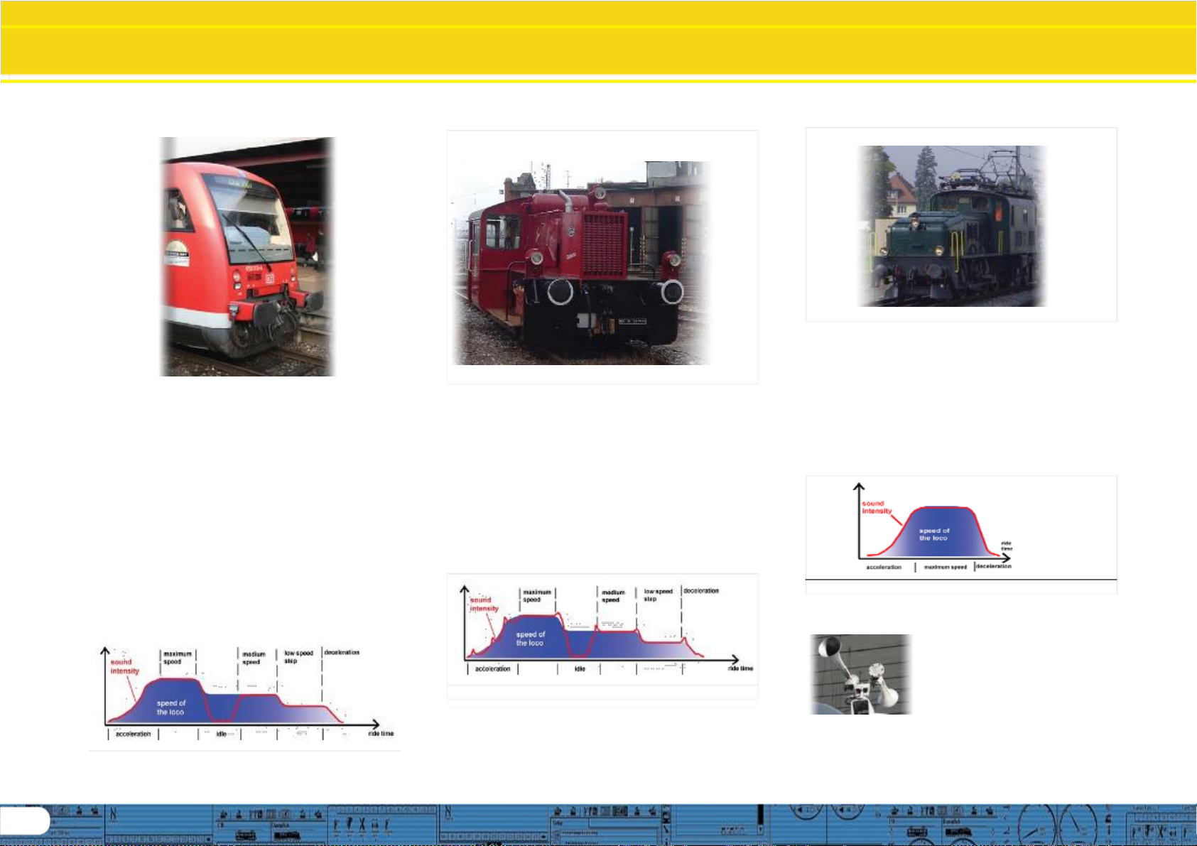
3.1.4. Diesel locomotive with manual transmission
(manual gear gear box)
Diesel locomotives withmanual transmissionemploypinion gear
for transmitting the power from the motor to the wheels
similar to automobiles. The clutch is pressed during shifting
from one gear to the next and thus the power transmission is
interrupted for a short moment. The shifting of gears can
clearly be heard in many a diesel locomotive with manual
transmission. With theLokProgrammer software you can either
store the original sound of gear shifting or you maychoose the
option „gear shift“ (User-SoundSlot14) as described inchapter
9.6.2:
Examples of diesel locomotives with manual transmission are
the German rail cars VT95orsomeshuntinglocomotives, since
manual transmissions are only practical in vehicles of relatively
low weight and with low maximum speeds.
Fig.7.: Performance of a Diesel Locomotive with Manual Transmission
3.1.5. Electric locomotive
There are different sound types for electric locomotives. On
the one hand the hum of theelectric tractionmotor(s)is audible;
it changes its pitch with the speed similar to diesel-hydraulic
locomotives.
Other electric locomotives generate very dominantfan sounds.
In some electric locomotives the sound of the fan is constant
and therefore the sound does not change during driving.
By and large electric locomotives are not as noisy as other
locomotive types and therefore they are ideal for applying
User Sounds such as the whistle, horn, compressor, etc. (for
more info please refer to chapter 9.5 and 9.6).
Fig.8.: Performance of an Electric Locomotive
3.2. User defined sounds
User-defined sounds („User-Sounds“)
couldbe horns andwhistles,couplerclank,
sanding, etc. These sounds can be
triggered by pressing a function button
on your throttle once you have
programmed them onto the decoder.
CurrentlyLokSound decoders supportup
to28 functionssuch as head lights, smo-
ke generator, etc. The latest versions of digital command
stations suchasthe ESU ECoS canfully utilizethis range.
LokSound Basics
3.3. Automatic / Random sounds
Random Sounds are triggered automatically and irregularly
and canbe used for safety valves, fans,compressors, etc.
With the LokProgrammer you can select the time between
Random Sounds (detailsin chapter 8.5.3).
Other possibilities for triggering sounds automatically such as
squealing brakes are contained in Decoder Settings and the
appropriate flow chart (see chapter9). Such sounds will be
triggeredat specific times based on those settings.
3.4. Digital system / Protocols
In this chapter we list all digital protocols for running model
trains and setting signals and turnouts that are supported by
the LokProgrammer.
3.4.1. DCC (NMRA)
DCC stands for „Digital Command Control“ and was formulated
as standardbytheNMRA (National Model RailroadAssociation).
Inthe earlystages operation was limitedto 14 speedsteps and
80 addresses; today up to 10,000 addresses and 128 speed
steps areavailable.
DCC is downward compatible in terms of control and decoders,
e.g. older decoders can be controlled with up-to-datecommand
stations / throttles and with certain limitations new decoders
can be operated and programmed with oldercontrol devices.
3.4.2. Motorola®
The Motorola®-protocol goes back to 1984 is one of the oldest
digital systems formodel trains. Due to its age the operational
options are limited.
The Motorola®-protocol can only handle 80 locomotive
addresses with14speedsteps and besidesthe headlightfunction
onlyfour additionalfunctionoutputs can becontrolled(functions
5-8 can beselected with the second Motorola®-address).
Sincethe Motorola®-protocolisstill used inmany digitalsystems
ESU decoders are designed to work with this protocol as well.
3.4.3. M4
Since 2004 the MFX®-system is onthemarket.Theoretically
this couldrunmore than16,000model locomotivessimultaneously
with 128 speed steps.
The LokProgrammer software deals with certain settings
somewhat differently to DCC.
For instance, instead of locomotive addresses the name of the
locomotive has to be entered (e.g.: „class 01“ or „ICE“). The
allocatement of certain parameters to the CVs is also different
toDCC.
Do not usethe DCC-CVs mentioned from chapter 3.5 onwards
for M4!
Whatdoes M4 mean?
At some points in thismanual you will notice the term „M4“ for the first
time and rightlywonder what this might mean.
This question canbe answeredquite simply: from 2009forward,M4 isthe
name of a data protocol that was chosen by ESU to be implemented in
their decoders. Decoders with the M4 protocol are onehundred percent
compatible with command stations using mfx®. At such stations (e.g.
Märklin® Central Station®) they will be recognized automaticallyand all
playing functions are available just like when using mfx®. On the other
hand, ourESU command stations using M4 will recognize all (Märklin®
and ESU) mfx® decoders without any restrictions and will still work
without any problems. As the (mutual) inventor of mfx® we can assure
you of this.
Inshort: thetechniquestaysthe same,onlythe namehas been changed.
3.4.4. Selectrix®
Selectrix® is another digital system. In contradiction to DCC
the locomotive addresses are not transmitted individuallybut in
groups. Thus it is limited to the driving sounds and Random
Sounds but it is not possibleto trigger any user defined sounds
(e.g.: a whistle or bell). Selectrix® is almostexclusivelyused for
N scale and Z scale; therefore it is also supported by the ESU
LokSoundmicrodecoder.
It is important not to confusethesesystemswhen programming
any sounds. For instance is it not possible to store any M4-
project files on a DCC-decoder let alone to replaythem.
3.5.CVs
3.5.1 Definition and application
CV stands for „Configuration Variable“. CVs can have values in
bits or bytes. The CVs with bytes can have a range from 0 to
255 while the CVs programmed in bits function as on / off-
switches.
Examples:
CV 63 (sound volume) is a CV that can be programmed byte-
wise witha maximum value of 192. Thevalue 0 means no sound
while 192 standsfor maximumsound volume. (150%)
In CV 49, bit 0 is a „switch“ for activating load compensation
(asper8.3.2). Ifthis bitset to0,loadcompensationis deactivated,
is it set to 1, and then load compensation is active.
TheNMRA(NationalModelRailroadAssociation)hasallocated
certain CVs to certain functions. For instance CV 1 is always
used for the address, CV 5 for the maximum speed.
Advantages / Disadvantages
Digital decoders can be programmed without the need of
comprehensive programming knowledge or equipment. Many
digital command stations also offer internal programming
menus.
Furthermore the programming with bits and bytes requires
littlememoryspace. Programmingsolelywith CVsisnoteasyto
remember and depending on the type of command station it
can be quite cumbersome.
Furthermore CVs have only limitedeffect on soundsinLokSound
decoders (e.g.: sound volume). The actual sounds cannot be
adjusted with CVs but depend on the actual sound recording.
In the LokProgrammer software CVs are shown in registers or
as slide controls and can therefore easily be set to the desired
values.
3.6. Further information about LokSound decoders
3.6.1. General
At the core of a LokSound decoder is a powerful processor. It
is supported by an audio amplifier and a sound memory that
can store up to 268.44seconds ofsound.
The eight channel mixer with active filter can replay eight diffe-
rent sounds simultaneously: One channel is reserved for the
driving sounds while theother seven can be used for othersounds
(such as bells, whistles, etc.), Random Sounds (e.g.:
automaticsafety valvesor shoveling coal), and brakesounds.
Alleight channels will be mixed to one output in the decoder
and transmittedto the speaker.
The memory of the LokSound decoder can be deleted at any
time to make room for new sounds. Thus it is no problem
whatsoevertomodifyasteamsounddecoderintodieselsound.
You can easily do that yourself with the aid of the ESU
LokProgrammer whenever you want to!
Please note: this unimpeded change of sounds is limited to
decoders sold for installation into locomotives by the user.
LokSound decoders that areinstalledinlocomotives bya model
train manufacturer may not always offer this option!
A field at the lower edge of the screen shows the available
memoryspace during programming(in seconds and bytes) as
well as the total capacity of the particular decoder. Select the
„Sound“ register and then one of the sound displays in order
to see this (also refer to chapter 9.).
If you wishto save some files but donot have enough memory
space onthedecoder you mayhavetodeletesomesoundfiles
from this project. Alternately you can shorten some of the
sound fragments with your audio-program.
3.6.2. Connecting the speaker
The speaker is the end piece of the sound equipment. Of
course we can only install small speakers into our model
locomotives.
Therefore the speaker must meet a very demanding
specification. ESU offers a range of speakers of different size
and for different decoder types.
Please note that the audio output of the LokSound v3.5 decoder is
designed for100 Ohm whilst v4.0 and XL require 4,8, and other
ohm ratings. Please seeyour decoder for specific speaker
ratings.
7
8
Tasks of the LokProgrammer
Software
3.6.3. Suitable sounds
ESUoffers many different soundfiles forall sorts of locomotives
on the website www.esu.eu. Please take note of the licensing
conditions mentioned in the appendix regarding the download
of sound files. Of course you can program your own sound
projects on your LokSound decoder.
Generally you may use all files in Windows *.wav-format for
LokSound decoders. WAV is the standard format for storing
sounds of anykind on windows. If the recording is noise, music
or speech makes no difference.
The files can originate from the CD-ROM supplied with the
LokProgrammer, they could be downloaded from the internet
or theycould be created by you.
Wave-files can be stored in different levels of sound quality on
the hard disc. The better the sound quality, the more memory
space isrequired.
In ordertoachieve optimal sound quality you should record and
edit wav files at CD quality (44100hz / 16bit). The program
automatically converts the files to the suitable
formatmatchingthe particulardecoder.
Hint:
With the advent of v4 decoder architecture a new high
capability conversion utility is included in the programmer
software, therefore best audio quality for all v4.0 decoders is
realized by recording and editing at CD quality (44100hz /
16bit, stereo or mono) and allowing the programmer software
to convert your files as they are imported into the sound
project. In this manual we cannot provide comprehensive
instructions on how to edit or convert sound to digital files and
how to save them on ahard disc. Pleaseobserve the manuals
thatwere supplied with your PC or with your audio card,
recording device, and the sound editing software you are
using tocapture and produce your user produced sounds.
3.6.4 Supported hardware
The LokProgrammersoftware as from version 2.5.0 supports
only the LokProgrammer 53450 „LokProgrammer V3.0“.
The number of supported decoders varies subject to the
LokProgrammer version.
Theversions from 2.6.1.SupportthefollowingESU-decoders:
• LokSound V3.5 with 8 and 16 MBit memory for 0 scale andH0
scale(DCCandMotorola®)
• LokSound micro for TT and N scale (DCC, Motorola® and
Selectrix®)
• LokSoundXL V3.5 for G and I gauge (DCC and Motorola®)
• LokSound M4 for 0 and H0 scale for the users of Märklin®
systems.
In addition the following (partly older product versions) are
supported:
LokSound V3.0, LokSoundXL V3.0, LokSound2, LokSoundXL
V2.0, LokPilot, LokPilotDCC, LokPilotXL,LokPilotXL DCC.
Software versions from 4.4.7 support v3.5 and v4.0 decoders.
The LokProgrammer software is subject to continuous
development. In order to assure that you always work with the
latest software version you should regularly call up the internet
update facility. Whenever a new version with extended
functionality and bug fixing is available it will be placed in the
download section on our website.
The appearance on the screen may change subject to the
features of a specific decoder. Therefore in certain cases only
some of the features described here will be active or even
more options may be available. Please always refer to the
manual supplied with the decoder.
4. Purpose of the LokProgrammer software
In the following chapters the program functions of the
LokProgrammer will be described. First the general functions
andthenthemorespecial possibilitiesofadjustingESUdecoders
(LokPilotandLokSound).
The appropriate CV inthe DCC protocolfor each option will be
named as well as which setting is supported by which ESU
decoder. LP stands for LokPilot, LS for LokSound.
Please bear in mind that you can only fully utilize the potential
features of a decoder with the latest firmware.
4.1. Overview
• Setting / changing of all parameters of ESU decoders: alloptions
can be set comfortably on the PC. Ofcourseit is still possible to
manually adjust any CV via digital command stations such as
theESUECoS-commandstation.
• Modification of sound files, that are stored on an ESU LokSound
module: itis possibletochangeall soundfiles onthe LokSound
module at any time, e.g. also at a later stage. Thus you can
compose your own sounds using anything as source that can
be saved on your PC: locomotive sounds, music, speech, etc.
There are no limits to what youcando.
It is for instance easily possible to change the sounds from a
steam locomotive to a diesel or electric locomotive - or vice
versa.
• Test new ESU sounds: With the aid of the virtual cab (see
chapter 6) you can test decoders on the programming track.
Limitations: Select decoders only allow full sound project
installs, no individual sounds may be written. V4 project must
not be protected in order to change individual files. Sound
project must be available and open in LSP (LokSound
Programmer Software) in order to change sound files.
Decoder sound cannot be read into the software from the
decoder. (See chapter 10 and on.)
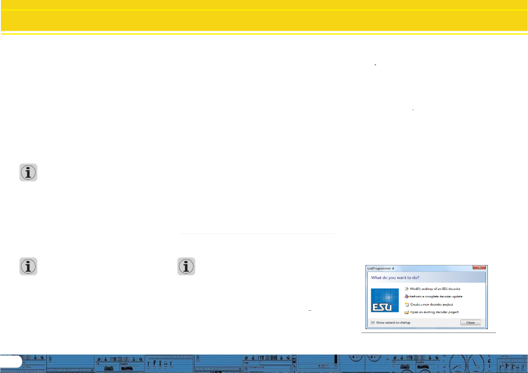
4. 2. Assistant
As soon as the software isstarted the assistant window pops
uponthemonitor.Thisenablesyoutocallupthemostimportant
functions of the program. Subject to which function you select
the appropriate window appears immediately. With the help
of the assistant you can deal with important tasks easily and
quickly.
The assistant helps you to carry out the following tasks:
• To read out decoder data for comfortable evaluation and
modification.
• To completely modify the sound files of a decoder in order to
easily change a steam sound decoder into one for a diesel
locomotive.
• To generate a completely new project
• To open an already saved project.
In order to do this, select the desired option and follow the
instructions in the small window
Fig.9. Assistant
Main Screen
5. Main screen
5.1. View Panes
According to the different tasks, the program is divided into
different viewpanes andmenus. Figure 10 shows the main
screen of the LokProgrammer software and its main
components:
• Drivers Cab: Here you can test decoders in an easymanner
• Read/Write CV’s: individual adjustment of CVs provided the
decoder supports DCC(NMRA).
• Decoder: for comfortable programming of ESU decoders with
agraphicdisplay
• Information: for viewing information regarding functions and
for general information about the file, such as type, country,
etc.
• Sound: this serves for modifying sounds or to generate new
sound compositionsforLokSounddecoders.
Fig.10.: Main screen
5.2. Task bar
Fig.11. Task bar
•File: in this menu you can do the following with projects:
NewProject, Open, Import Project (converts v3.5 projects to
v4.0 projects (Project to be converted must be first saved to
version 2.7.9 or version 4.7.+ software as a v3.5 file)
You can also call up the internet update facility (refer to 2.5)
and close the LokProgrammer software.
During file save, alldata, settings and sound files will be written
into the project file. Project files are saved with the ending
”.esu“ for v3.5 decoder and .esux for v4.0
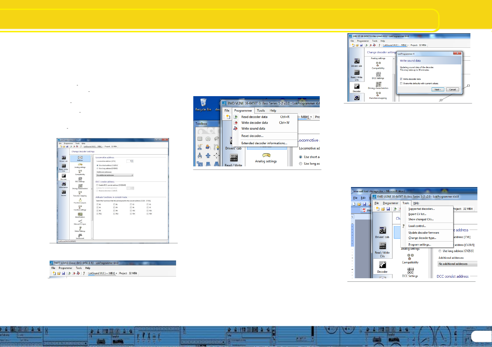
• Programmer: here you can read and write decoder data and
write sound files. Extended decoder data such as type of
decoder and version number ofthe firmware can also be read
here.
Fig.12.: Menu „Programmer“
“Read Decoder Data“: Prior to changing any data on the
decoder it is advisable to read out all decoder data. Place the
locomotive on the programming track and make sure the
programming track is correctly connected.
Then click “Read decoder data“ in the task bar at the top of
the screen. The program startsto read the data immediately.
Pleasebe patient,this process may take one or two minutes.
The status isdisplayed inthe progressbar.
“Write Decoder Data“: The CVs contained in the project file
will be written onto the decoder connected to the
LokProgrammer. Click „Continue“ in the window that opens
first in order to write the CVs. All data on the decoder will be
replaced by the new data.
“Write Sound Data“: The entire sound project will be written to
the decoder using this command, replacing all sound data.
Partial sound information cannot be written, therefore to use
this command the project file for the decoder is required to
have been opened first, using the file menu. A submenu
dialog opens immediately after issuing this command: (next
column)
Fig.13.: Write Sound Data „Programmer“
If “Write decoder data” is checked, the decoder data in the
project will be written first, followed by sound. If “Overwrite
defaults with current values” is checked, then the current
decoder data will become the defaults for when the
command “reset decoder,,,” is issued. When “Next” is
clicked, the information write begins and will take up to 30
minutes to complete, depending on amount of sound data
being written.
“Reset Decoder“: Resets decoder to either factory
defaults or current defaults if “Overwrite defaults” has
previously been used.
5.3. Tools
Fig.14.: Menu „Tools“
The Tools menu provides options that provide information
about the current decoder and allow you to take certain
actions in regards to the current decoder you are working
with: (see next page)
7
9
Main Screen page Cont.
“Supported decoders,,“: This provides a listing of all the
decoders currently supported by the programming software
version you are currently using.
“Export CV List,,“: Creates a .txt file and opens a file save
dialog, allows you to save a listing of the current CV’s for
future use, such as comparisons, etc.
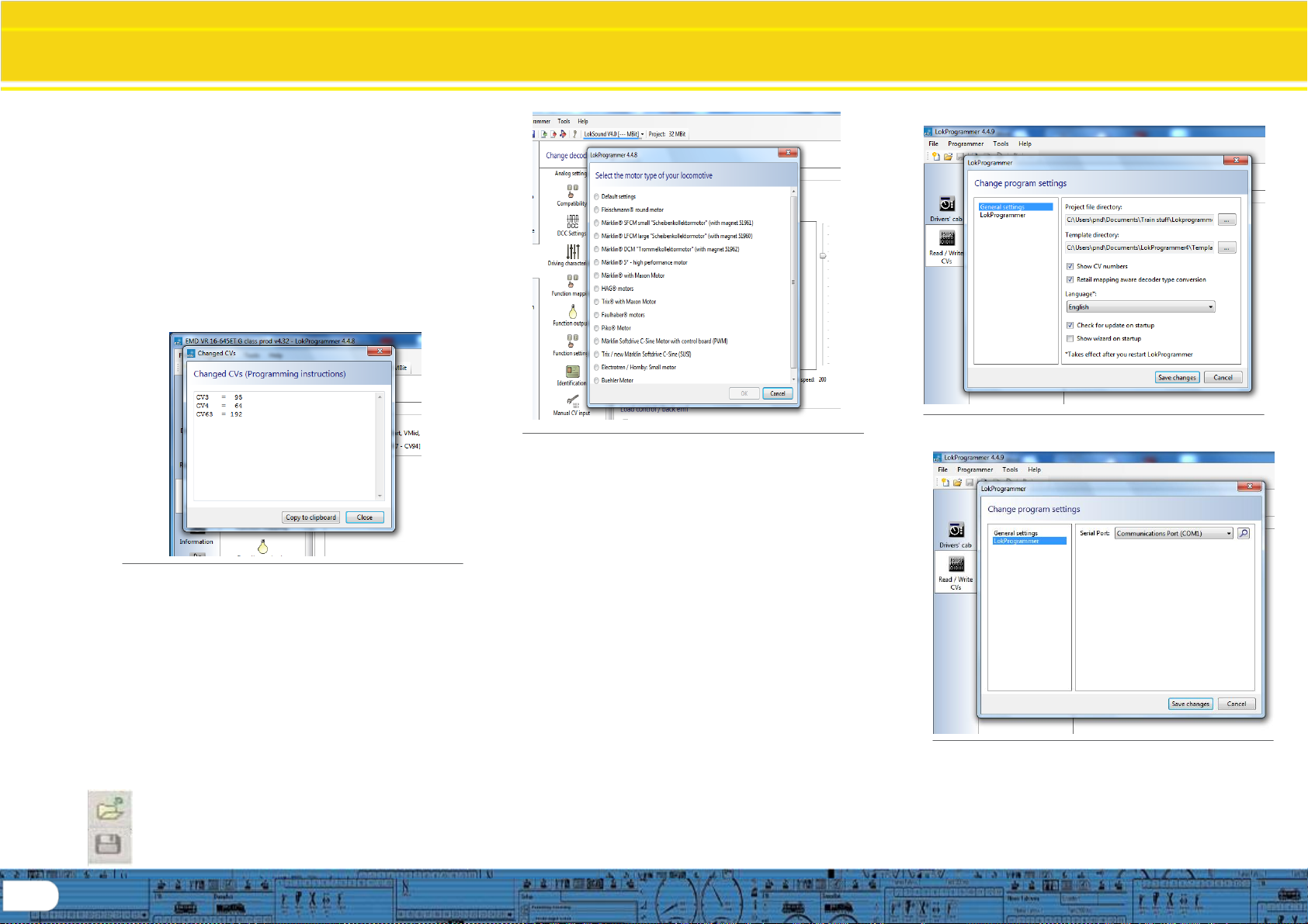
“Show changed CV’s,,“: Opens a sub-dialog box that
displays a listing of only the CV’s that have been changed
since the last time the project file was opened. This is
extremely useful if you intend to perform an action such as
manually programming a decoder. See figure 15 below:
Fig.15.: Changed CV’s, sub dialog „Tools“
“Load Control,,“: Opens a sub-dialog box that lists common
DCC motors that have performance templates built into the
software based on each motor type. Selecting one from this
list that matches or closely matches the motor you are using
in your model and provides a starting point for setting up
your model. See fig 16 at top of next column:
10
Fig.16.: Load Control, sub dialog „Tools“
“Update decoder firmware“: Commands an activity that will
either confirm the current decoder is at the current firmware, or
will write the current firmware to the decoder. Note, this action
is also incorporated in the commands that write decoder data.
“Change decoder type“: This allows you to open a project such
as one for a LokSound Micro or Standard, and change the
decoder type to another supported decoder, such as an XL.
Note; it is not possible to change a decoder type from a v4
project to a v3.5, this option is reserved for working within the
same decoder architecture.
“Program Settings“: Opens a sub-dialog that allows you to set
or change current programmer settings; such as file
directories, languages, display CV’s, etc. This is also where
com settings are controlled for communication with the
LokPprogrammer hardware. See figures 17 and 18 next
column:
Fig.17.: Program Settings, sub-dialog„General“
Fig.18.: Program Settings, sub-dialog „LokProgrammer“
Drivers Cab, Decoder
Information, Read / Write CV’s
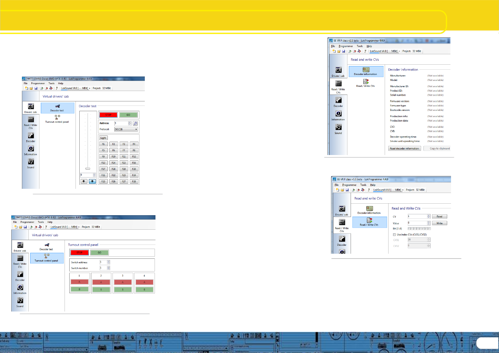
6. Driver’s cab
With the aid of the driver’s cab you can test decoders and sound
projects. You can run the locomotive and trigger all functions.
Therefore you can test run your locomotive on the programming
track with the LokProgrammer.
Fig.19.: Virtual Driver’s Cab
Included in the Drivers Cab section is the Turnout Control Panel
which allows you to also test the Switch Pilot decoder.
Fig.20.: Turnout Control Panel
There are some limitations though: the LokProgrammer power
supply limitsthe permitted current to about 400 mA. Should the
motor of the locomotive draw a higher current then the over
current protection will be triggered and the power to the
programming track will be shut off. This is indicated by the
blinking yellow LED on the LokProgrammer. In this case
deactivate the virtual cab and then turn it on again.
All otherfunctions inthis register areself explanatory:You can
entertheaddressand thenumber ofspeedsteps.Pleasemake
sure that the speed steps matches the ones set on the
LokProgrammer.
The LokProgrammer can run locomotives in DCC format, as
from version 2.5 also in the Motorola® format. Due to the
hardware the LokProgrammer cannot handle M4. Test your
M4 projects in the Motorola® format.
Please check that your programming track is fully isolated from
the mainline of your layout prior to turning on the virtual cab.
Should there be any electrical bridge it could damage the
LokProgrammer (also refer to 2.2.)!
Activate the locomotive for the test run by clicking the field
„Activate Cab“.
Control the speed of the locomotive with the slide throttle.
Clicking into the appropriate fieldsturns functions on and off.
Up to function F12 you may also press the numbers on your
computer keyboard.
Please bear in mind that running a locomotive with the
LokProgrammer cannot and should not substitute a command
station: due to the limited power of the power pack you will
not be able to run more than one locomotive at any one time.
The virtual cab simply gives you the opportunity to quickly test
run your locomotive.
7. Decoder Information, Read / Write CVs
In the register „Read / Write CVs“ you can perform 2 actions, first
in the list is an icon labeled “Decoder Information” (see figure 21),
when the button titled “Read decoder information” is clicked, the
decoder currently connected to the programmer will be read, and
the information will be displayed on the decoder information dialog
as shown in figure 21.
Also within this register you can read and write individual CV’s on
the currently active decoder attached to the programmer (see
figure 22) , this is done as follows: Select the register „Read /
Write CVs“. Then to ReadaCV:
• Enter the number of the CV you want to read in the upper
data entry field.
• Press the button „Read CVs“.
• The result will be shown in binary and decimal format.
Fig. 21.: Decoder Information
Fig.22: Read / Write CV’s
Write a CV:
• Enter the number of the CV you want to write in the field at
the top.
• Write the new value of the CV in the lower data entry field.
• Click onto the button „Write CVs“.
• The CV will be overwritten with the new value.
• The Index CV’s are also shown, and should be set correctly
in order to write values correctly.
Note: Similar to POM (Program on the Main), does not change
sound project values.
11

Change Decoder Settings
Address
8. The “decoder settings” register
All settings regarding the motor control and CV configuration
(such as Function mapping, Sound settings, DCC settings,
etc.) of the decoder are handled in the “Change decoder
settings” register. Please note that this Register is initially empty
when you start the program. Information will only be displayed in
this field after you have generated a new project, opened an
existing project or read out a decoder. Projects are an image of
all data stored on a decoder.
Fig. 23.: The „Change decode settings“ register
The buttons that let you go to the different options are on the
left of thescreen.Besides movement andsound behavior you
12
can adjust specific settings such as brake mode, address, etc.
On the following pages we will explain the parameters and
options.
8.1. Decoder address
8.1.1. Address (CV 1, CV 17, CV 18)
All modifications of the address are done in the window
„Address“. Subject to the decoder type so called short (two
digits, CV1) or longaddresses (four digits, CV17 and CV18)can
be used.
Pleasenotethatanysettings intheseCVsareonlyeffective for
operation with NMRA-DCC compliant command stations.
When operating decoders with the Märklin® / Motorola®-
protocol a separate address, namely the Märklin®-address is
valid.
Youmayenter asecondaddress forM4-decoders inMotorola®
mode in order to activate F5 to F8. Normally this would be the
address of the decoder plus 1.
8.1.2. Consist settings (CV 19)
The DCC consistaddress is useful for multipletraction.It is also
possible to activate function outputs for consists as well as
function buttons for consist mode.
In some cases it is desirable to set certain functions in consist
mode in such a way that the function is actually triggered by
pressing one button in both (or all) locomotives (e.g.: lights).
Click onto the appropriate button of the function that should
be activated in consist mode.
8.2. DCC / Analogue
Supported analogue modes and settings (CVs 13, 14, 50,
125, 126, 127, 128, 129, 130). In analogue mode load
compensation is not active. Therefore by using the appropriate
slide control you can adapt the start voltage and the maximum
speed separately for AC or DC Analogue mode to match the
characteristics of your motor or transformer. Furthermoreyou
can select thefunctions that should be active in analoguemode
(DC, ACor both; CV 50).
8.2.1. Active functions in analog mode (CV13, CV14)
Sincemostanalogue layoutsdonothave input devicestotrigger
functions, these parameters allow you to pre-select which
functions should be automatically active in analogue mode.
It is recommended to turn on the sound (default value F1 for
European projects, F8 for USA) and the smoke generator of
steam locomotives (often F4). Also lighting should be active if
desired. Checked functions cannot be controlled during analog
operation, they are either on (checked), or off (unchecked).
8.2.2. AC Analogue mode (CV 29, CV50)
Activates the AC analogue mode, and allows setting of Start
voltage (minimum speed) (CV127) and Maximum speed
voltage (CV128).
8.2.3. DC Analogue mode (CV29, CV50)
Activates the DC analogue mode, and allows setting of Start
voltage (minimum speed) (CV125) and Maximum speed
voltage (CV126).
8.2.4. Analogue voltage hysteresis (CV 130,
CV129)
The motor will stop when the voltage falls below start voltage
minus motor hysteresis voltage. Functions will be activated
when the voltage reaches the motor start voltage minus the
function difference.
8.3. Compatibility
ESU v4 decoders have certain characteristics built into them to
allow them to be configured to enhance operational
compatibility with certain dcc command stations. Compatibility
settings are enable by checking certain boxes in the
programming software. These selection boxes are identified in
the compatibility section. Options available are:
8.3.1 LGB MTS (CV49.5)
Checking this box enables serial function mode for f1 through
f8 and improves compatibility with LGB Multi Train Systems
command stations
8.3.2 Marklin Delta mode (CV49.2)
This option enables Marklin Delta mode in support of Marklin
delta dcc systems.
8.3.3 Zimo Manual function (CV49.6)
Zimo manual function can be enabled by checking this option.
8.3.4 Serial user standard interface (CV 124.3)
Selecting this opetion will enable the decoder Serial User
Standard Interface (SUSI), this will the decoder to communicate
with up to 3 SUSI devices.

Change Decoder Settings
DCC Settings/Driving Characteristics
8.4. DCC Settings
There are 2 groups of items you can configure in this view
window as shown in figure 24. These are RailCom settings
and Speed step mode.
Fig. 24.: The „DCC Settings“ register
8.4.1 RailCom settings CV29, CV28)
These settings allow the enabling or disabling of RailCom
information. Checking the first option enables RailCom feedback
and allows setting the other 3 items as you desire. LokSound v4
decoders are RailCom enabled and thus offer you the features
RailCom provides.
8.4.2 Speed step mode (CV49, CV29)
Here you can adjust more settings for running your locomotive.
In DCCmode you havethe optionof settingthespeed steps manuallyto
14, 28 or 128. Optionally youcancheck the first option box andallow the
speed stepstobedetectedautomatically.
8.5 Driving characteristics
Items within this view window allows the adjustment of
several variables that affect overall driving features that
are available, such as; acceleration and deceleration
(momentum), brake options, speed trimming, and other
power handling features.
Fig. 25.: The „Driving characteristics“ register
8.5.1 Acceleration and deceleration (CV3, CV4)
Selecting the check boxes for acceleration and deceleration
enables and sets momentum values for speeding up and slowing
down. Setting momentum values allows the model being driven
to act in a more realistic manner, and it allows certain sound
features to be enjoyed.
Acceleration (CV3) can be adjusted using the variable
slider within a decimal value range of 1 to 255 providing
acceleration times of .1 seconds up to 63.75 seconds.
Deceleration time (CV4) can be adjusted using the
deceleration time across the same range, allowing you
to set values for coasting. Higher Momentum settings
also allow certain sound features to operate realistically,
such as coasting sounds and acceleration sounds.
8.5.2 Allowed brake sections (CV27, CV134,
CV123)
A variety of automatic brake sections can be enabled
for the v4 decoder; this allows the layout on which the
decoder is running to be configured to trigger
locomotive braking when a section of track is reached,
perhaps a curve, and then the locomotive returns to
prior speed upon exit. The various types of brake
section detection are enabled by checking the boxes
that match your layout(s).
ABC brake mode can be set for either right rail
(CV27.0), left rail (CV27.1), or both having a more
positive voltage than the other. Voltage difference
(CV134) to enable the trigger can be set with a variable
slider with a range of 4 to 32, providing a significant
flexibility in setting up layouts. The second slider
(CV123) allows setting the amount of speed reduction
over a range of values from 0 –255, allowing automatic
speed reduction from very slight to a complete stop.
Also available is compatibility with ZIMO (HLU) brake
sections (CV27.2) by selecting the option to enable
them.
You can also enable auto stop brake sections carrying
a either a forward DC polarity (CV27.4) or reverse DC
polarity (CV27.3) by selecting the appropriate check
box.
8.5.3 Constant brake distance (CV254, CV255,
CV253, CV27.7)
Constant brake distance allows you to precisely control
where your trains will stop on your layout. This effect
works in conjunction with brake sections, and it can be
used without brake sections by setting only CV254 to
determine a distance for braking, along with setting
CV27 bit 7. With these settings made the v4 will
generate a stop command when ever speed control is
set to speed step 0. Stop distance will be based on the
value set in CV254. See v4 decoder manual chapter
10.6 “Constant Brake Distance for detail.
13
...

14
ChangeDecoderSettings
DrivingCharacteristics/Functions
Fig. 26.: The „Driving characteristics“ register
8.5.4. Reverse mode (CV 29)
A tick at „Reverse mode“ changes the direction of travel
and the directional characteristics of the headlights. This is
useful in case the wiring has been done incorrectly
(swapping of track
leads or motor leads).
8.5.6 Trimming (CV66, CV95)
The trim function allows you to set the maximum speed
separately for forward and reverse movement. The factor
that is used to multiply the motor voltage, results from
dividing the CV-value by 128 (forward CV 66 and reverse
CV 95).
8.5.7 Power Pack (CV 113)
V4 decoders (HO and N) provide for the installation of capacitors
or power packs (so called “keep alive” devices). CV113 allows
control of the amount of time the device is active. Setting range is
0 to 255 via the adjustment slider; an estimated active time is
shown to the right of the setting in seconds. Information for
installing capacitors or power packs can be found in the decoder
manual chapters 10.9 (configuring) and 6.11 (wiring).
8.5.8 Preserve Direction (CV124.0)
Checking this option keeps the direction constant when the v4
equipped loco transitions from DCC control to Analog controlled
track sections.
8.5.9 Starting delay (CV124.2)
Usually, when the LokSound V4.0 sound is idling and you turn up
the throttle, the locomotive begins to move only after the Diesel
engine has reached notch 1. A steam loco will even release its
brakes first and fill the cylinders. Although this behavior is very
prototypical, one might not like it because it causes some delay.
You can control this startup delay by simply not checking this
option. This will cause the LokSound V4.0 decoder to immediately
start moving when the throttle is turned up. However, the start up
sound will not be synchronized with the motion anymore.
8.6. Function views
Both LokSound V4.0 and LokSound micro V4.0 decoders have
identical function mapping. M4 and XL decoders have different
screen displays. The display will shift when the decoder type for
any given project is changed; therefore, the screen display
depends on decoder type. Shown here is the display for V4
standard and micro decoders. A great deal of information is
available in the v4 decoder manual concerning function mapping.
Of course, which sound is assigned to which sound slot may vary
depending on the decoder project. You will find a list with all
available project files “Download/Sound files/LokSoundV4.0/“ on
our home page at www.esu.eu. You may also view and print a list
with all functions and the sound slots employed.
The LokSound V4.0 decoder offers powerful and flexible function
mapping options:. Each function button can switch as many
outputs as desired. Each output can be activated by several
function buttons. Function buttons can be linked (e.g.: F3 AND F5
pressed simultaneously)
Function buttons can be inverted (e.g.: NOT when F8 is on).
Besides the buttons F0 to F28 you can also incorporate the
direction of travel or the speed (locomotive is moving / has
stopped)
You may connect as many as 5 external sensors. While
many model train enthusiasts need precisely these functions
for optimal running of all their locomotives setting up
function mapping represents so to speak the “free style”
version of decoder programming. Take your time to
understand the concept behind it before you start changing
any settings. For a complete review of all function mapping
CV’s, see the v4 decoder manual.
HINT: Even if you do not have LokProgrammer hardware,
you can still use the software as an aid in making mapping
changes in conjunction with the “Show changed CV’s”
capability.
Fig. 27.: The „Function mapping“ register
The function mapping view is arranged as a matrix with
vertical columns for conditions, physical outputs, logical
functions and sounds. Horizontal rows list each condition
and function key for use in mapping as desired. See figure
27.
8.6.1 Function mapping, “Conditions”
The input block (conditions block) shows which condition is
required to achieve a certain output. Conditions are for
instance “F3 On” or “Locomotive is stationary with direction
set to forward, and F8 is switched on”. Configuring the
outputs to behave as desired begins by deciding which
function or function key you wish to configure to enable an
output that will perform the desired action when the function
is on, or off.

ChangeDecoderSettings
FunctionMappingCont.
The figure below; figure 28, displays an example of
setting a condition against function key F11 in which
the direction is set to reverse, and the key must be ON
in order for the condition to equate to “true”, This then
becomes the condition that must be fulfilled in order for
the desired output to be enabled.
Fig. 28.: Establishing a condition for F11
In this manner all the functions available to the decoder
can be configured to behave as desired. The next task
is to set the desired output for the function.
8.6.2 Function mapping, “Physical outputs”
In the output block it is shown what action must be
carried out when the condition(s) is/are met. This could
be, for instance, switching a function output or a sound
effect. LokSound decoders have up to 12 physical
function outputs. “Headlights“and “Rear lights“are used
for lighting, the remaining ones are freely available.
Other functions include “Shunting Mode“, “Acceleration
/ Deceleration On/Off“ as well as virtual functions like
“Sound On/Off“. The function buttons (“F buttons“) of
your command station or throttle activate the function
outputs. Generally, F0 is the lighting button, while we
count the remaining buttons from F1 upwards.
See figure 29, next column, for an example of
configuring the Physical output for F0 to enable the rear
light to come on when the condition “F0 is on and
direction is reversed” becomes true.
Fig. 29.: Setting a Physical output for Rear Light
Complicated lighting configurations can be set by selecting more than 1
output. For example, we wish to have the front light on bright when
running forward, and dim when running in reverse. this can be done
setting front light(1) and front light(2) on, and then setting the function
outputs for front light(1) as on and front light(2) as dim in the function
outputs section. (See figure 30 and 31)
Fig. 30.: Setting a Physical output for Front / Rear
8.6.3 Function outputs, “Configuration”
Configuring the function outputs is done on a separate
screen from the mapping portion, each output can be
configured discretely, and some outputs such as Front
and Rear lights, and Aux1 and Aux2 can each have 2
configurations, to satisfy certain needs, such as
running with the front light on bright when going
forward, and on dim when reversed. There are many
configuration options available, as pictured in figures
31 and 32 dropdown menu options:
Fig. 31.: Physical output configuration for Front(2) dim
Fig. 32.: Setting a Physical output to trigger smoke chuff
15

16
ChangeDecoderSettings
FunctionMappingCont.
8.6.4 Function mapping, “Logical functions”
Logical functions may be applied to any of the function
keys selected for mapping. As with the other parameters
defined by the mapping columns, it is not required that a
logical function be selected, this is an additional option to
provide control in order to get the desired effect. Figures
33 through 34 display the various items the can be applied
to the function key selected.
Fig. 33.: Logical function column
Figure 33 indicates the Logical function column, the next 2
figures show the logical function contents. Assigning
logical functions to function keys enables some very
powerful actions that are available with the v4 decoder
family, as shown below: (figures 34 and 35)
Fig. 34.: Logical function contents, part 1
Note:multiplelogicalfunctionsmaybeassignedtoeachfunction
key,inthiswayonecanfullyconfigureakeyasdesired.
Fig. 35.: Logical function contents, part 1
ListedherearedescriptionsofeachLogicalfunction:
Acceleration-assigningthisoptiondisablesmomentumeffects
Switchingmode–thisoptionhalvesspeed,usefulinyardoperations
Dynamicbrake–effectivelyhalvesthedecelerationmomentumvalue
(CV4)
Firebox–producesafireboxflickereffect
Dimmer–reducesthebrightnessofallphysicaloutputsthataresetto
“dimmable” by 60%
Gradecrossing–enablesgradecrossinglightingeffects,asconfiguredin
thefunctionoutputsection
Dopplereffect–simulatesaDopplersound effectbasedonspeedwhen
enabled
Fadeoutsound–whenenabledfadesthesoundtothevolumesettingfor
“Fade sound” (CV133) in the “sound settings” section; allows simulating
goingintotunnels,buildings,etc.
Dieselnotchup-fordiesel/electricsoundprojects,allowsnotchingupof
onenotchperkeypress(~1seccycle),orengageformultiplenotchpoints.
Notchesupregardlessofspeed.
Dieselnotchdown–notchdownasabove. Note: onceengagedmanual
notchingremainsineffectuntillocomotiveisstoppedandnotchpointisat
idle.
Shiftmode-whenselectedsoundflowpathwillbranchonthosesound
flow charts where “shift” is used as a condition, such as “shift = true” (e.g.
alternatestartuppathsuchascoldstart,dynamicbrakeactionsassociated
withdynamicbrakeengaged,suchasenginerpmmoves toidle followed
bynotch4)
ESUsmokeunit–whenengagedwillturnonsmokeeffectsassociated
withintelligentsmokeunits,suchasESU, KM-10,Kissandothers,also
standardsmokeunits. Note:alsorequiressettingofappropriatefunction
output,andsmokeunitsettings
Volumecontrol–whenset,allowssettingvolumein6stepsbytogglingthe
functionkeyonandoff,onceperstep. Changesthemastervolumein6
steps(CV62)
Disablebrakesound–when engagedturnsoffautomaticbrakesound
(CV459(CV32=1))
Uncouplingcycle–turns onautomaticcoupleraction,alsorequiressetting
offunctionoutputcouplertypeandfunctionsettingssectionforautomatic
uncoupling.
8.6.5 Function mapping, “Sounds”
Hereistheareaoffunctionmappingwheresoundsarelinkedtospecific
functionkeys. Ifsoundslotshavebeennamed,thenamewilldisplayinthe
listwhenexpanded. Youcanassignmultiplesoundstoasinglekey,and
youcanassignsoundstomultiplelocations.Ifdesired. Seefigure36
below.
Fig. 36.: Mapping sound to function key
ChangeDecoderSettings
Functions/Identification/CVs
8.6.6 Function settings, “General” and “Automatic uncoupling”
Asmentioned in8.6.5above,whenmappinglogical
functionstoafunctionkey,insomecasesyoushouldalso
use Functionsettingsinorderto enabletheresponse you
desirewhenthefunctionkeyisengaged. Generalsettings
areforconfiguringlightingeffects,andallowyoutosetthe
blink frequencyforlightingsituationsthatrequireblinking
lights (CV112),andforsettinggradecrossingholdingtime
(CV132). Holdingtimeistheamountoftimethegrade
crossingeffect isenabled.
Automaticuncouplingis whereautomaticuncouplingis
enabled(CV246),andwhereyoucansettheuncoupling
speedacrossarangeof1–255(sameasthespeedtable
range),defaultis1(CV246). Pushtime(CV248)isthetime
insecondstheautomaticpushisineffect;andMovetime
(CV247)isthetimeinsecondsthelocomotivemoves away
from the uncoupled car(s). Of course “time” relates directly to
distancetraveled atthespeedsetfor thedurationofthe
automaticuncouplingcycle. See figure 37.
Fig. 37.: Configure Function settings
8.7. Identification
8.7.1 Data fields, “User identification”
Theuseridentificationfieldsareopenfieldsthatcanbeusedforany
purpose. These are designated as “User ID #1” and “User ID #2”.
CV’s are CV105 and CV106 respectively. Value range for both is 0 –
255andtheycanbesetindividually or together. Setting these CV’s
doesnotchangeanydecoderbehavior,theyareanopencode
sectionandcanbeusedforanypurpose,perhapstotrackacertain
version, or function key structure. Default value is 0 for both CV’s.
Seefigure38
Fig. 38.: User Identification
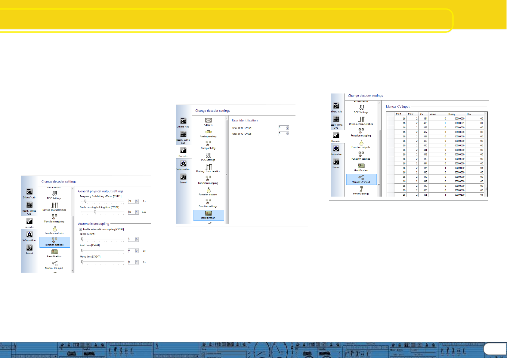
8.8. Manual CV Input
8.8.1ManualCVInput
Thissectionofthechangedecoderdatascreensismadeavailable
shouldyouwishtomakemanualCVchangeswithoutusingthe
preformatteddecodersetupscreensandviews. Itisalsoveryuseful
for researching CV’s. WhenyouexportthedecoderCVlisting(See
“5.3 Tools”, Export CV list) the text file that is created during the export
willconsistofthesamedatadisplayedinthisview.
8.8.2CVchanges
CVchangescanbemadedirectlybyoverwritingthedatainanyof
the data fields; “Value”, “Binary”, or “Hex”,simplyenterthevalueyou
wishandthentaboutofthefieldandthedatawillbechangedandthe
othertwodatacolumnswillupdate. Ofcourseitismucheasierto
enter direct numeric data in the “Value” column than it is to write
BinaryorHexdata.
Afteryouarefinishedmakingchanges,thenewvaluesmaybe
written to the decoder using “Write decoder data” (See “5.2
Programmer”,Figure12)
Note:Theabilitytomakemanualchangesisverypowerfuland
shouldbeusedwithcare. Considersavingthechangedproject
fileunderanewnameinordertoprovideawaytorewritelast
knowngooddatatothedecodertorecoverfrommistakes. See
figure39.
Fig. 39.: Manual CV Input
8.9. Motor Settings
Hereiswhereyouconfigurespeedtable,loadcontrol,PWM
frequency,andoverloadprotectionsettingsonthev4decoder
series. Informationpresentedheredealsdirectlywithmaking
desiredsettingsusingtheLokProgrammertooltoconfigurethe
decoder,thereforethelevelofdetailpresentedisnotatthesame
level asisfoundinthev4decodermanual. Pleaseusethe
detailedinformationfoundinthedecodermanual,chapter10,as
thepreferredsourcefordecoderinformation.
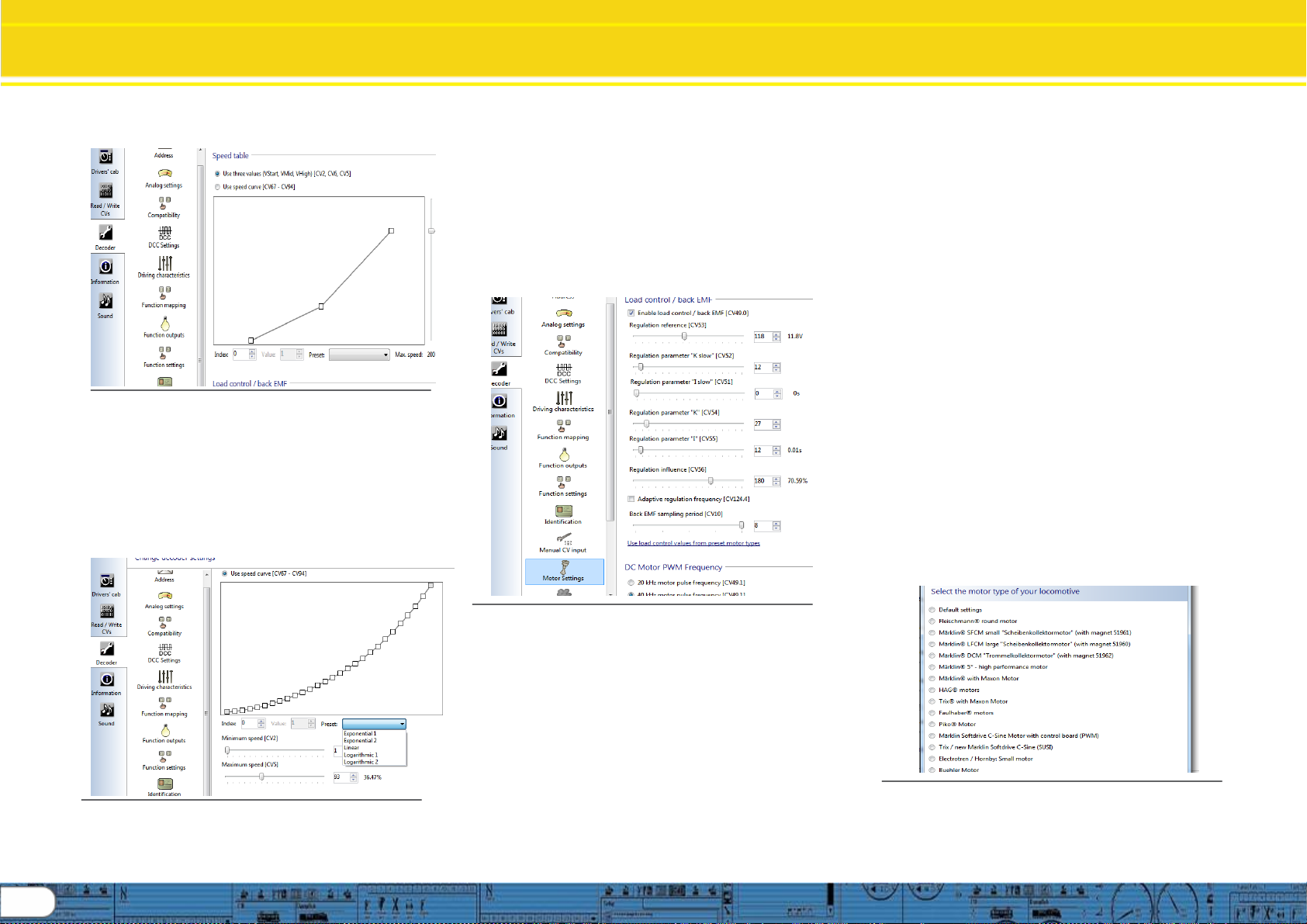
8.9.1Speedtableselectionandconfiguration (CV2,CV
5,CV6,CV26,andCV67-97)
Hereyoumayselecteithera3pointspeedtable(figure40)ora
customspeedcurve(figure41). Ifyouusethe3point tableyou
shouldsetminimum andmaximumspeed(CV2andCV5)and
thenpickthemidrangespeed(CV6)asdesired. Youmayalso
usethesliderontherighthandsidetosetbothmaximumand
midrangespeeds. Inordertoavoidpossibleroughorunusual
running,pleaseensure
17
18
Change DecoderSettings
MotorSettings
midrangespeedis higherthanstartspeedandmaximum
speedishigherthanmidrangespeed(CV2<CV6<CV5).
Fig. 40: 3 point speed table
Youmayalsodefineyourownspeedcurve:simplyenter
thedesiredvaluesintheCVs 67to94(alsorefertoFig.16).
Thedecoderwillsuperimposethese28valuesontothereal
speedsteps.Thus,youcanadaptthedrivingperformance
optimallytoyourlocomotive. Anotheroptionisavailable
usingthespeedcurveoption,thereare5predefinedspeed
curvesstoredintheprogrammersoftware,youmayselect
anyofthesebysimplyclickingontheoneyoudesiretostart
with,andthenyoucanmodifythemasdesired. Seefigure
41.
Fig. 41: Speed curve options and set up
Speedcurveshapeissetbyadjustingthe28pointcurveas
desired,thenminimumandmaximumspeedissetasitis
with the speed table (CV’s 2 and 5), the decoder then fits the
Speedcurvebetweentheminimumandmaximumspeedsettings
resultinginasmooth28pointspeedcurvewithinthedecoder. Please
seethedecodermanual,chapter10formoredetail.
8.9.2 Load control / Back EMF (CV’s 53, 52, 51, 55, and 56)
LoadcontrolcompensationisenabledviatheLokProgrammerby
checkingtheboxatthetopoftheloadcontrolsection,followingthat,
the CV’s can be adjusted as desired. HINT:Ifthedecoderisinstalled
in a model locomotive, there is an “auto set” feature you can use to set
theinitial parameters. See decodermanual,chapter11fordetailson
howtousethis feature. Thenifyouneedfurtheradjustmentyoucan
“read decoder data” to load the automatic settings into the
programmerforfinetuning. Seefigure42.
Fig. 42: Load control / back EMF setup
LokSounddecodersenableyoutoadaptloadcompensationtothe
motorwithCVs53,54and55.Iftherecommended values above
donotleadtoacceptableresults,youcanfurtheroptimizethem.
Especiallyfortheslowdrivingsector(speedstep1)theLokSound
V4.0withCV 51andCV52tochangethegaincontrol.Thishelpsto
avoidanyjerkingwhiledrivingextremelyslowly.
ParameterK,storedinCV54,influenceshowstronglyloadcontrol
will affect thedrivingperformance.Thehigherthevalue,themore
loadcontrolwillrespondtoanychangesandtrytoadjusttherevsof
themotor.ParameterKneedsadjustmentifthelocomotiveruns
unevenly(jerks). ReducethevalueofCV54by5andtest-runthe
locomotivetoseeifthereareanyimprovements.Repeatthese
stepsuntilthelocomotiverunssmoothlyatspeedstep1.
ParameterI,storedinCV55,provides importantinformationtothe
decoderonhowmuchinertiathemotorhas.Motorswithlarge
flywheelsnaturallyhavemoreinertiathansmalleronesorcorelessmotors. Adjust
parameterI ifthelocomotivejerkssomewhatjustbeforeitstops orjumpsatlower
speeds(lowerthirdofthespeedsteprange)orsimplydoesnotrunsmoothly.
Increasethevalueby5startingwiththeinitialvalueformotorswithverysmallorno
flywheels. Reducethevalueby5startingwiththeinitialvalueformotorswithlarge
flywheels.Testagainandrepeatthisprocedureuntilyouarriveatthedesiredresult.
InCV53,yousettheEMFreferencevoltagegeneratedbythemotoratmaximum
revs.This parametermayhavetobeadaptedsubjecttothetrackvoltageandthe
efficiencyofthemotor. Ifthelocomotivereachesmaximumspeedwhenthethrottle
issettoaboutthree-quarterandthetopthirdofthethrottlehas noinfluenceonthe
speed,thenyoushouldreducethevalueofCV53.Reducethevalueby5–8and
testthelocomotiveagain.Repeatthisprocessuntilthelocomotivejustreachesits
maximumspeedwhenthethrottleisfullyopen. Ontheotherhand,ifthelocomotive
movestooslowlyatfullthrottlethenyoushouldincreasethevalueofCV53stepby
stepuntilthemaximumspeedisreached.
TogetherwiththeLokSoundV4.0decoderanadditionalCV52hasbeenintroduced
whichseparatelydetermines thegaincontrolconsiderablyforthewholeslowdriving
sectorinspeedstep1. If youarenotsatisfiedwiththedrivingbehavior whenthe
locomotivedrives slowlyorstarts,whileeverythingisfinewiththemediumandhigh
speedsteps,youshouldincreasethevalueofCV52by5-10higherthanthevalue
setinCV54. Hereyoucanadjusttheinertiaofthemotorseparatelyforslowspeeds
andstartingfromastop.ThedesiredvalueistobeenteredintoCV 51.The
parameters “K slow” and “I slow” jointly influence the behavior at speed steps 1 and 2
while the parameters CV 54 (“K) and CV 55 (“I”) are responsible for theremaining
speedsteps.Thedecodercomputesaspeedcurveinordertoavoidanyabrupt
changes.
Thedecoderoperatesexworkswithamutable(adaptive)regulationfrequencyto
drivethemotoraspreciselyaspossible.However,asaresultsomemotorsmight
showanastybuzzingnoise. Forsuchmotorsyouareabletosettheregulation
frequencyonaconstantvaluebycheckingtheboxtoenableadaptiveregulation
frequency. YoumayalsoadjusttheBackEMFsamplingperiodusingtheslider,
valuesrangefrom4to8(CV10).
Fig. 43: Load control preset motors
YoumayapplypresetsthathavebeentestedbyESUformanytypesof
motors by clicking the option “use motor control values from preset
motor types “ See figures 42 and 43. See v4 decoder manual for mote
detail.

Change DecoderSettings
MotorSettings/Smoke/Sound
8.9.3DCMotorPWMFrequency(CV49.1)
LokSounddecodersloadcontrolworksnormallywith40kHz.
Sometimesitcanbeusefultoreducethisfrequencybyhalf:
Formotorswithlittlepowerduetohighinductivity.
•Ifsuppressors(suchascapacitors,chokes,etc.)disturbload
controlbutcannotberemoved(e.g.someolderGützold®
locos).
CheckthedesiredsettingintheProgrammersoftwaretoset
CV49bit1asdesiredforeither40or20kHz.
8.9.4MotorOverloadProtection(CV124.5)
ESUv4decoders offer asettingtoenablemotor overload
protectionif needed. Thisisseparatefromthenormalthermal
protectionforthedecoderasdescribedindecodermanual,
chapter6.10.1. Motoroverloadprotectionenablesthedecoder
tomonitorBEMFreactionsofthemotortovariousoperational
loads;ifthedecoderdetectsmotoroverworking(possiblydue
tomechanicalissuesorstress)thedecoder willstopthemotor
withoutaffectingotherdecoderoperationorsound.
8.10. Smoke Unit
ESUv4DCCdecodersenableawidevarietyofoutput
choices,oneofwhichis smokegenerators,suchas ESU
smokegeneratorsorthosefromothervendors.
YoucanwireanykindofloadsuchasLEDs(lightemitting
diodes),smokegeneratorsorsimilardevicestothefunction
outputsprovidedthemaximumcurrentdrawislessthanthatof
thedecoderoutput.Thepermittedmaximumcurrentdrawper
functionoutputislistedinchapter20ofthedecodermanual
under „Technical Data.“,pleaseconfirmyourintendedsmoke
generator loadissuitableforyourdecoder. Itisimportantto
staywithinthecurrentcapabilitiesofthedecoderyouare
installingandprogramminginordertoavoidpossibledamage.
Thissectionofthedecodersettings worksinconjunctionwith
severalfunctionsettingitemslistedinsection8.6ofthis
manual,suchasfunctionmapping,physicalandlogical
outputs,andfunctionoutputs. Pleaseset up allareasinorder
tocontrolyoursmokeoutputasdesired.
ESUv4XLdecodercandriveseveraltypesofsmokeunits
directly,thestandardv4decoderandthemicro v4maynotbe
able to fully drive a smoke unit, but you can still provide “smart”
orsounddrivensmokeunitoperationifyouconsideroptions
suchasSUSIorrelays. Placingmagnetsorfoilsystemsor
othercomplicatedtriggerdevicesisnotrequiredifyouusethe
smokeunitcapabilityofESUdecoders. Seefigures44, and
thefunctionmappingfiguresinsection8.6fordetail.
Fig. 44: Smoke Unit set up
8.10.1 ESU Smoke unit (CV’s 140,138,139)
HereyoucansetvariablestocontrolESUandothersmokeunits. You
cansettimeofoperationuntilsmokeunitpoweroffacrossarangeof1to
120(1to600seconds)(CV140). Youcantrimbothfanspeed(CV138)
andtemperature(CV139)toprovidesmokedensitytoyourchoosing
usingtheappropriateslidervalue. Trimsettingsdefaultto128(100%)
acrossarangeof0to255.
8.10.2Smokechuffs(CV’s 143,141,142)
Thissegmentofthesmokeunitsetupallowsyoutocontroldurationofthe
smoke “puff” relative to trigger distance (CV143), across a range of 0-255
providingupto1seconddurationpertriggerevent. Minimum(CV141)
andmaximum(CV142) durationofthesmokepulseisadjustableina
rangefrom 0-255,thisprovidesamaximumsmokepulsedurationof1
second,withminimumandmaximumrangingfrom0–1.04seconds.
Thesesettingsallowthesmokepulsetovarywithlocomotivespeed,
similartothewaythechuffsoundvarieswithspeed.
AllsmokesettingsaredirectvalueswhichlendthemselvestoPOM
programming for easy fine tuning. SUSI interface will provide “intelligent”
smokeifyourdecoderfunctionscannotmeetthecurrentratingforthe
smokeunit. IfusingSUSIinterfacepleaseremembertoenableSUSIfor
thedecoder,seesection8.3“Compatibility” for details.
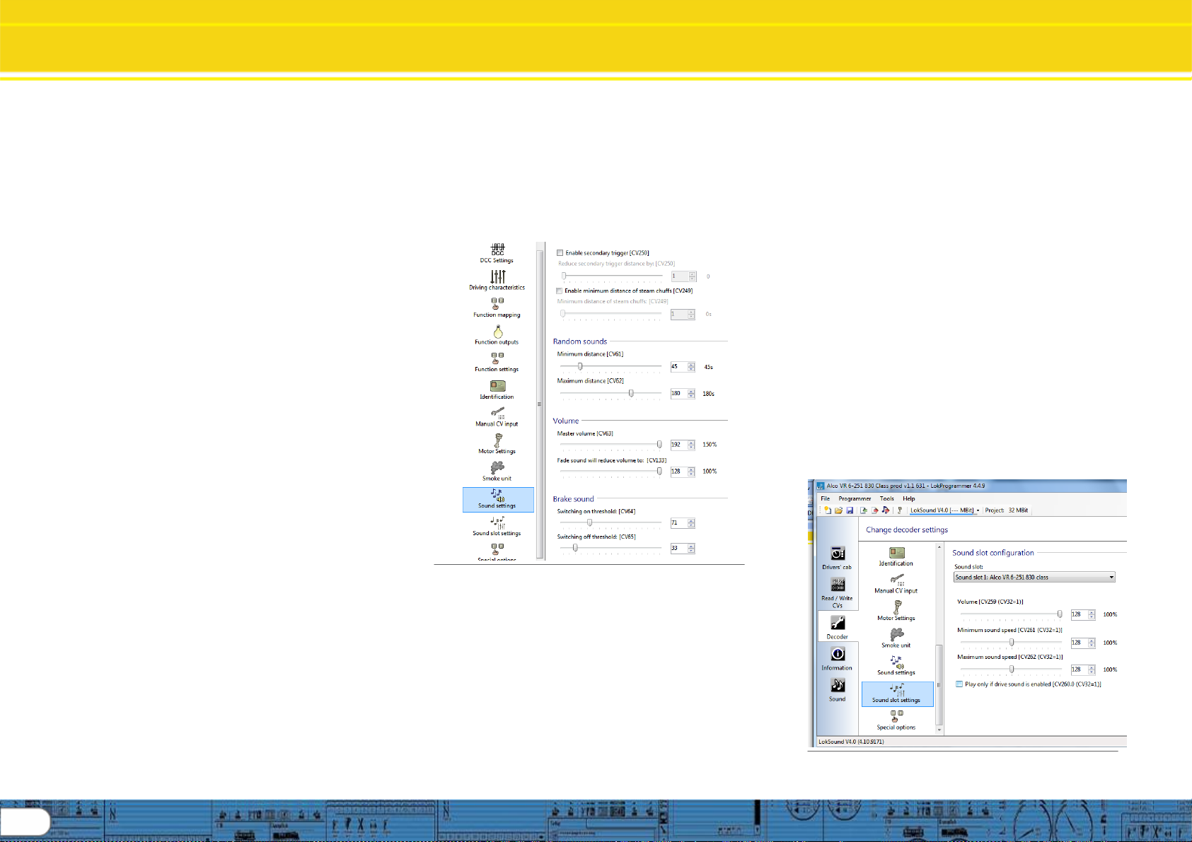
8.11. Sound settings
Soundsettingssectionallowsconfigurationofseveralareasthataffectthe
reproduction of soundsstoredonthedecoderwhenthesoundprojectis
writtentothedecoder,thusallowingtheusertoselectoperationtomatch
themodellocomotive. Pleaserefertofigures45and46aseachsection
iscovered.
Fig. 45: Sound settings part 1
8.11.1Soundselection(CV48)
Version4decodersandsoftwareallowtheuseofpre-
configuredgroupsofsoundswhicharekepttogetherin
templatesthatcanbeplacedinasoundproject. Examples
arewhistleandhornpacks. Withineachgroup,eachspecific
sound,suchasaNathan-P3horn,aregivenanindexnumber
whenthepackiscreated, thenumberrangeis1through16,
withaspecificsoundassignedtoeachnumber. Usingthe
Soundselectionconfigurationnumberyoucanselectwhich
hornorwhistleyouprefertosoundwhenthehornpackis
assignedtoafunctionkeyviafunctionmapping. CV48can
alsobewrittendirectly,allowingforchangeswhileoperating.
(Powercyclemayberequiredafterchange)
8.11.2Steamchuffs(CV’s 57,58,250,249)
Synchronizingsteamlocochuffsoundtowheelrevolutionis
performedinthissectionoftheprogrammer. Anabbreviated
methodislistedhere,forfulldetail,pleasereadthedecoder
manual,chapter13.4.
(Continuednextpage)
19
20
Change DecoderSettings
Soundsettingscontinued
Ifusinganexternalchufftrigger,suchasmagnetsoratrigger
switch, check the option titled “use external sensor”, then you
haveanoptionwiththesliderbartoenterthenumberof
triggersrequiredtomakeachuff. E.G.ifamagnetwas
mountedon agearthatrequired4revolutionstoprovide
enoughdrivewheelprogresstorequireachuff,thenyouwould
put4inthesliderbox;thiswouldmeanit wouldtakeatotalof
16revolutionsofthegeartoequateto4chuffsperdrivewheel
revolution.
Beforecomplicatingyourassemblybydevisingatrigger
method, try the chuff option “Play steam chuffs according to
speed”. Select that option, and then set the chuff sync sliders
inordertoproducethecorrectautomaticchuffsounds. A
significantnumberofmodelerswhooncealwaysusedchuff
triggershavefoundautomaticchufftimingisjustasaccurate
andsignificantlyeasiertosetup.
CV57is usedtosetthechuffsequencefor1completedrive
wheelrevolutionatspeedstep1(1of28).Timeonedrive
wheelrevolutioninseconds;calculatetheinitialvalueforCV57
bydividingthetimeby.128for4chuffsperrevolution,or.103
for3chuffsperrevolution. Enterthecalculatedvalue
(rounded, no decimal) using theslider. Testandadjustuntil
thecorrectchufftimingisfoundforspeedstep1of28.
CV58isusedtosetthehigherspeedchufftiming. Dothis
steponlyafteryouhavefoundthecorrecttimingforspeedstep
1. Increaselocospeedtospeedstep4of28,observechuff
rate,ifchuffrateisnowlessthan4chuffsperrevolution,
decreasethevalueofCV58(defaultis43unlessithasbeen
overwritten). Ifchuffrateistoohigh,increasethevalueof
CV58. Makeincrementalchangesuntilyougetthecorrect
chuff rate at speed step 4. Note: use “read decoder data” to
findthecurrentvaluesinthedecoder. Note:inpracticeyouwill
find CV’s 57 and 58 work together in a balance, you may find
severalsettingsthatwillwork,.
Minimumdistanceofsteamchuffs (CV249)isusedtofine
tunehighspeedrunningof steamsounds,forinstanceifthe
chuffsoundathighspeedsoundslikeitisruntogetheror
“machine gun”, youcanadjustthetendency forthesoundto
becomeoverspeed withthissetting. To usethis,checkthe
optiontoenable,andputatrimmervalueinwiththeslider.
Hint: startatmidpointandthenadjustupordownasneeded.
Hint:itmaybequickeroveralltousePOMfortheabove,and
then return to the programmer and “read decoder data” to
capturethevaluesintoyourproject.
Pleaseseethedecodermanual,chapter13.4forfulldetail.
Enablesecondarytriggercheckbox(CV250)isusefulinseveral
instances. Ifyou wishtomimicthesoundofanarticulatedsteam
engine,suchasa2-8-8-0orsimilar,youcanchecktheboxto
enablesecondarytrigger,andputavalueinwiththesliderbartoset
acycletimeforthesoundofthedriversrunningslightlyoutofphase
witheachother. Itisalsousefulifyouaremodelingadualengine
dieseloramulti-channelsteamsound(Inthiscase,thesound
projectmustbebuiltusing2channels,seethechapterforthesound
modelingsectioninthismanual.)
Pleaserefertofigure46fortherestofSoundsettingsinformation:
Fig. 46: Sound settings part 2
8.11.3Randomsounds(CV’s 61,62)
Randomsoundsarecyclicsoundssuchascompressor,airpopoff,
pumps,etc.thatareheardfromlocomotives whenstandingor
running. Thesesoundsdonotinvolvebrakesorprimemover
sounds. Thefrequencyanddurationofthesesoundsiscontrolled
bythesettingsestablishedinthissectionoftheprogrammer.
CV61isusedtosettheminimumtimebetweensoundingofa
randomsound,inseconds,usingtheslidertosetthevalue. CV62is
usedtosetmaximumtimebetweensounding. Randomsoundswill
thenoccurbetween thetwosettings,onarandom basis. Ifthe
soundprojecthasfiverandomsounds,thenallfivewillbeheardat
varioustimes,ifonlytworandomsoundsareavailable,thenof
courseitwillbeonlythetwothatareheard.
8.11.4Volume(CV’s 63,133)
Mastervolumesettingfortheoveralldecodersoundlevelissetwiththis
slider (CV63). Themastervolumecanbesetacrossarangeof0to192
withtheslider,producingamastervolumerangeof0to150%. Individual
soundslotvolumescanbesetalso,seesection8.12forthosesettings.
Fadesound(CV133)canbeusedtomimicthesoundreduction
experiencedwhenenteringtunnels,goingbehindobstaclesorother
timeswhenyouwishtofadethemastervolume. Magnitudeofthesound
fadeoutissetwiththeslideracrossarangeof0–128whichproducesa
faderangeof0to100%volumewhentriggered.
8.11.5Brakesound(CV’s 64,65)
Brakesoundonandoffissethere,usingtheslidersthatchange valuesin
CV’s 64 and 65. Brake sound on is triggered by reducing the speed step
settingwiththespeedcontrol(throttle). Therefore,ifyouwishthebrake
soundtobemoresensitivetospeedcontrolchange,setthe “on”
thresholdtoahighervalue. Afterthebrakesoundisengaged, off
sensitivity is set by the “off” threshold. Set these values as you wish. If
usingagoodmomentumsettingalongwiththedesiredon/offthresholds
you can “play” the brakes suchthattheywillsoundthesamewaya
prototypelocomotivedoes.
8.12. Sound slot settings
Thesoundslotconfigurationviewallows youtosetfouritemsinregards
toeachsoundslot;volume,minimumsoundspeed,maximumsound
speed,andlocktodrivesound. Eachofthe27soundslotscanbe
named(fromtheSoundsection)andhavetheabovesettingsindividually
sethere. Seefigure47and48fordetail:
Fig. 47: Sound slot settings A
Table of contents
Popular Motherboard manuals by other brands


Neoway
Neoway N25 Series user guide

Avalue Technology
Avalue Technology BC680R user manual

PCchips
PCchips Tidalwave W30 user guide

ARTESYN EMBEDDED TECHNOLOGIES
ARTESYN EMBEDDED TECHNOLOGIES ATCA-7350 quick start guide

Ublox
Ublox C030-R412M user guide

Global American Inc.
Global American Inc. 3303788 user manual