23
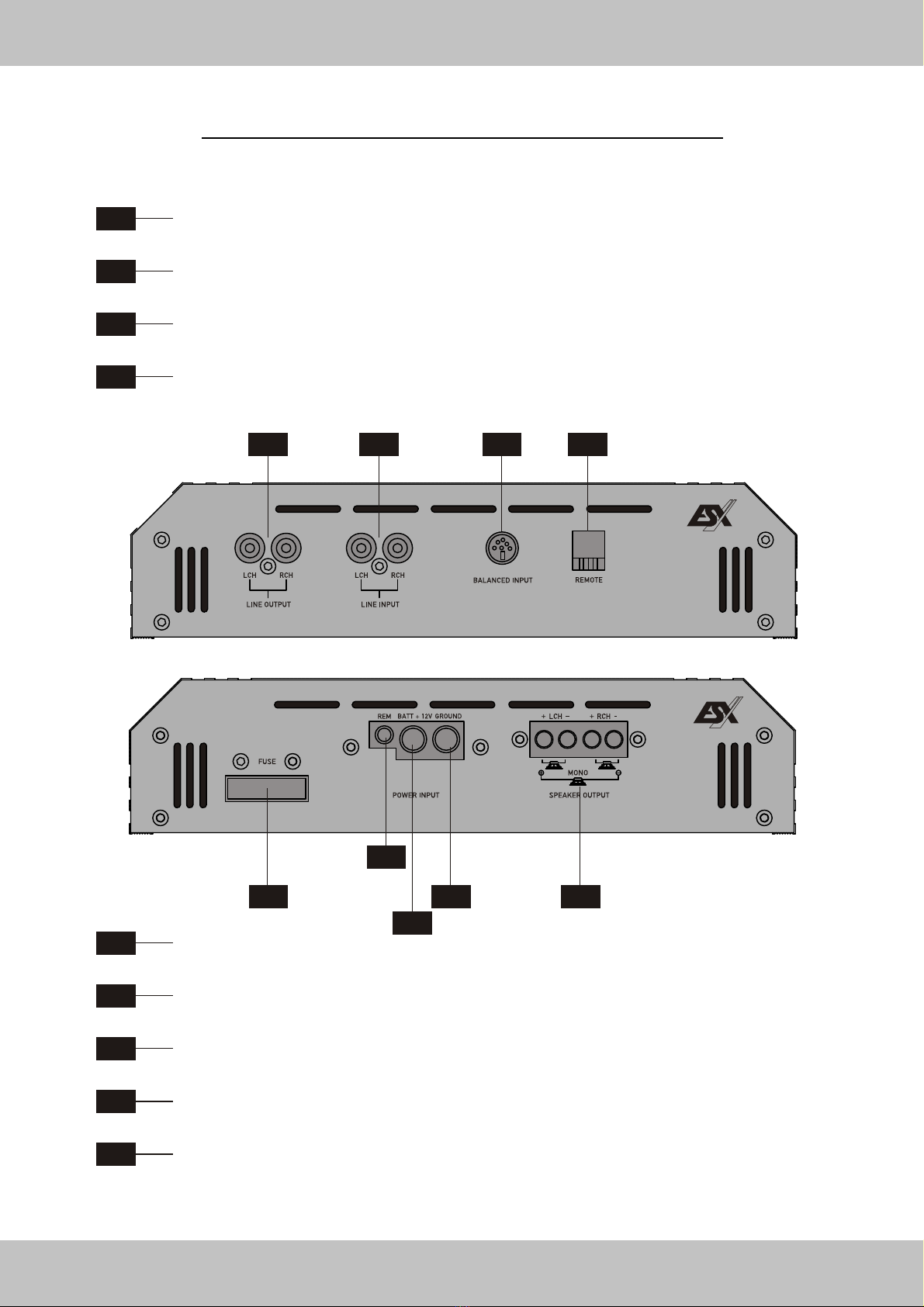
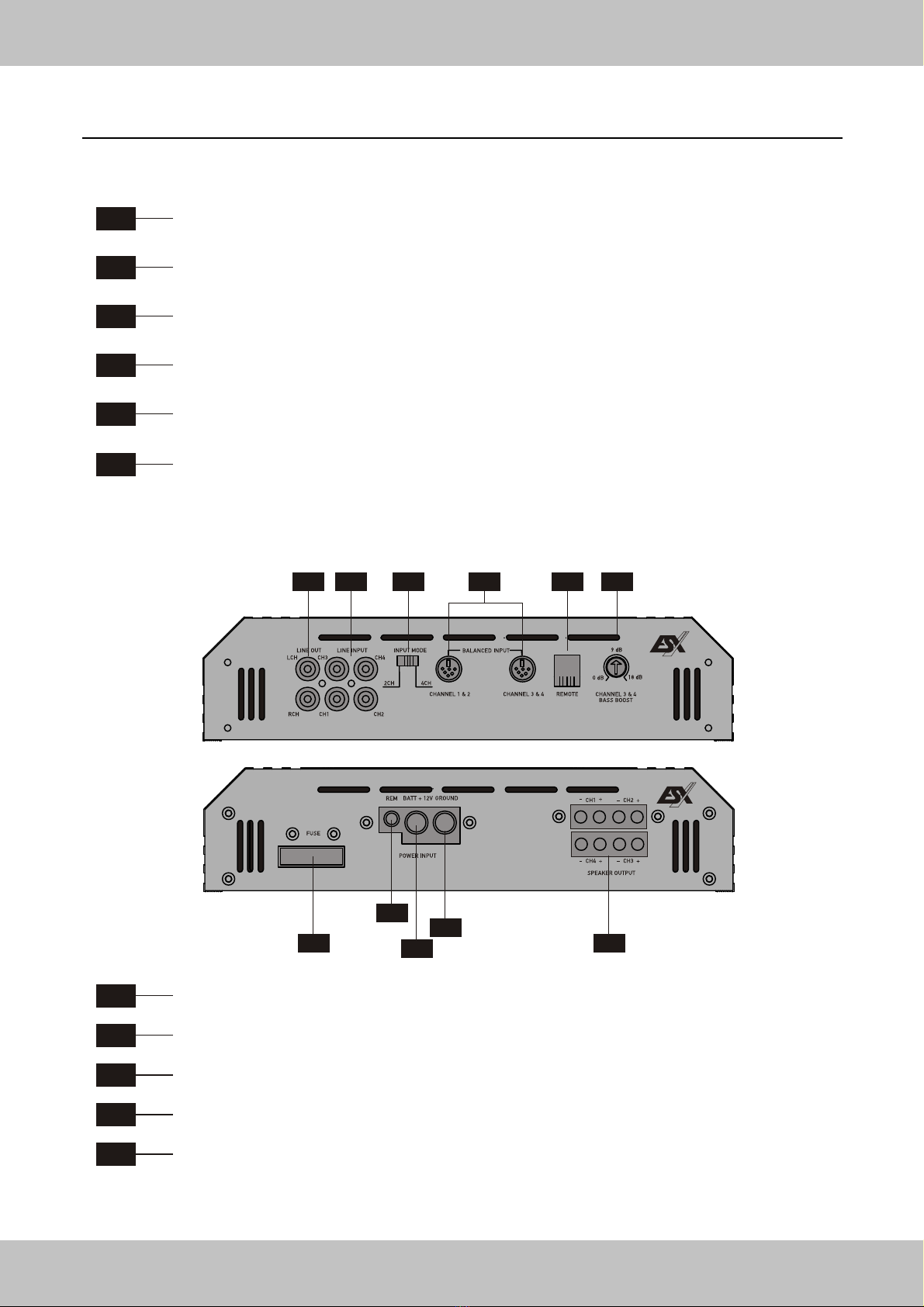
FUNCTIONS & CONTROLS TOP-PANEL
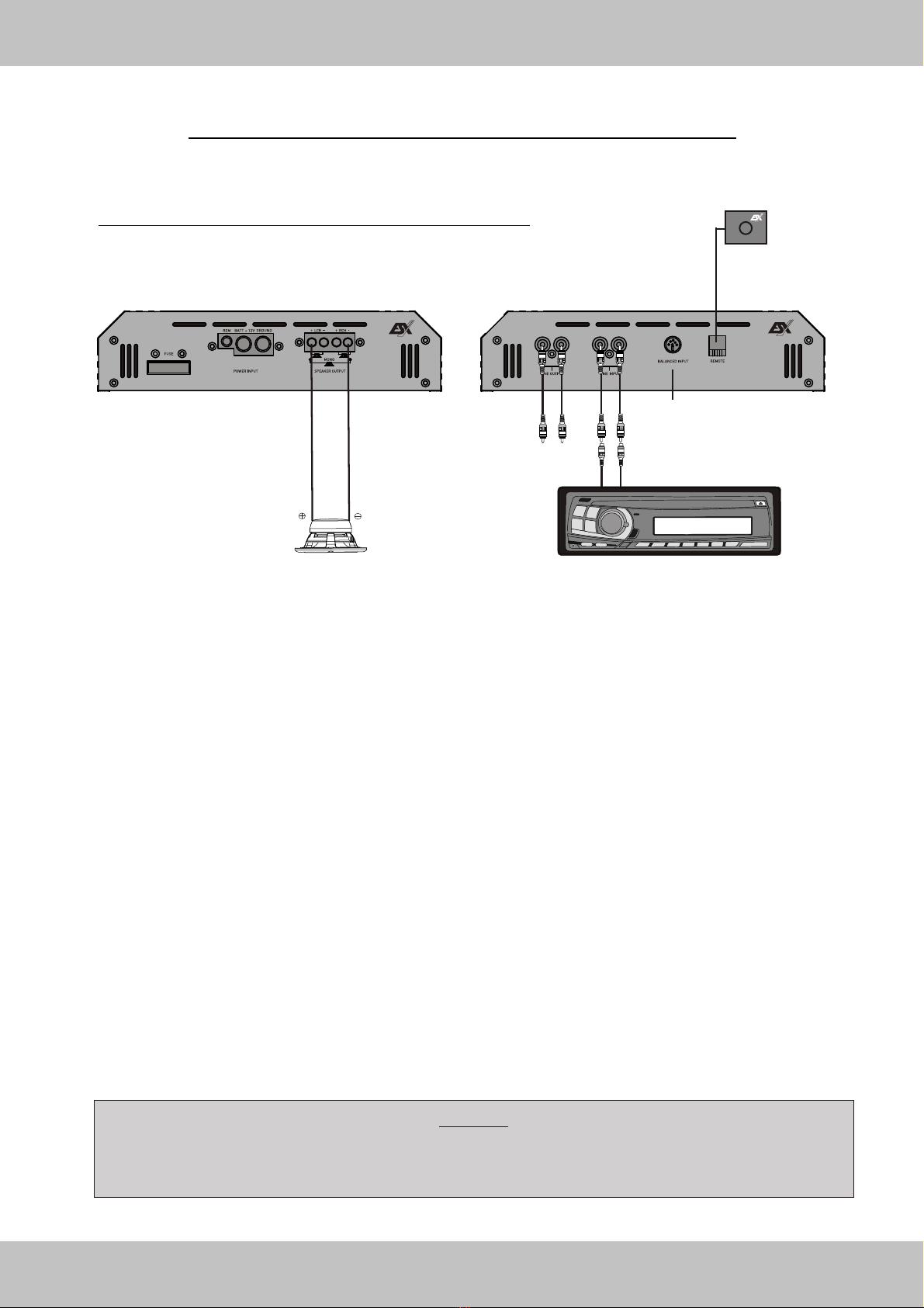
2-Channel Amplifier VE1000.2 / VE1800.2
T1 ACOUSTIC PHASE SHIFT LEFT
Allows to adjust the phase modulation (acoustical center) of the left channel between 0 - 180 degrees.
T2 ACOUSTIC PHASE SHIFT RIGHT
Allows to adjust the phase modulation (acoustical center) of the right channel between 0 - 180 degrees.
T3 MONO – In this position the phase modulation is only mono (for a bridged Subwoofer).
It is adjustable between 0 - 180 degrees by the T1 switch (See page 32).
STEREO - In this position the phase modulation is adjustable for each channel separately (T1 and T2).
OFF - In this position phase modulation is not activated. T1 and T2 are out of function.
If this display lights up red, the integrated protection circuit is activated.
T4 DISPLAY –If the display lights up white, the amplifier is in operation mode.
T11 LOW PASS
Allows to adjust the threshold frequency of the LOW PASS-Filter and the frequency response of the
Loudspeaker Signal is limited upwards. The threshold frequency is variable from 40Hz up to 4000 Hz.
T9 12dB STEREO / 24dB MONO
If this pushbutton pressed, the slew rate of the LOW PASS-Filter in mono mode will be
raised to 24 dB. Is this pushbutton the slew rate is limited to 12 dB in stereo mode (See page 32).
T10 CROSSOVER SELECTOR
HIGH PASS – In this position the HIGH PASS-Filter is activated. This mode is required for speakers
with a diameter from 8,7 cm up to 16 cm.
FULL In this position a full range signal is conducted to the speakers. It is required for speakers
with a diameter over 20 cm. T5 / T7 / T9 / T11 are out of function.
BAND PASS / LOW PASS In this position Lowpass-Filter is activated. This operation mode is
required for subwoofers. By using T7 and T11 the subsonicfilter can be adjusted (See page 32).
T7 HIGH PASS / SUBSONIC
Allows to adjust the threshold frequency of the HIGH PASS-Filter and the frequency response is
limited downwards. The threshold frequency is continously variable from 10Hz up to 2500Hz.
If T10 is set to BAND PASS / LOW PASS, you can adjust the subsonic frequency. (See page 32)
T5 12dB STEREO / 24dB MONO
If this pushbutton pressed, the slew rate of the HIGH PASS-Filter in mono mode will be
raised to 24 dB. Is this pushbutton the slew rate is limited to 12 dB in stereo mode (See page 32).
T12 OUTPUT SELECTOR
HIGH PASS – In this position the HIGH PASS-Signal controlled by T5 & T7 is conducted to F1.
FULL In this position a FULL RANGE-Signal is conducted to the RCA Outputs F1.
BANDPASS / LOW PASS In this position a LOW PASS-Signal controlled by T9 / T11 and T5 / T7
is conducted to the RCA Outputs F1.
T8 BASS BOOST
This controller allows you to adjust the Bass Boost from 0 to 18dB.
Please use the Bass Boost carefully.
T6 INPUT GAIN
This controller allows to adjust the volume (input sensitivity) of the input signal from 0,15 up to 9 Volts.