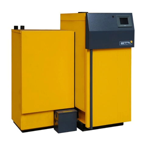
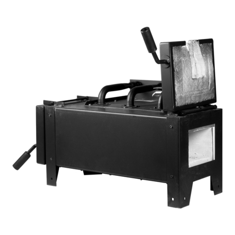
eta SH 20P User manual

2020-07-21
EN
0000000371
V.012
2503
939023-004
TWIN pellet burner
40-50 kW
Installation

ETA Heiztechnik
Gewerbepark 1
A-4716 Hofkirchen an der Trattnach
Tel: +43 (0) 7734 / 22 88 -0
Fax: +43 (0) 7734 / 22 88 -22
www.eta.co.at

3
Contents
1 General . . . . . . . . . . . . . . . . . . . . . . . . . . . . . . . . . . . . . . . . . . . . . . . . . . . . . . . . . . . . . . . . . . . . . . . . . . . . . 4
1.1 Preface. . . . . . . . . . . . . . . . . . . . . . . . . . . . . . . . . . . . . . . . . . . . . . . . . . . . . . . . . . . . . . . . . . . . . . . . . 4
1.2 General information . . . . . . . . . . . . . . . . . . . . . . . . . . . . . . . . . . . . . . . . . . . . . . . . . . . . . . . . . . . . . . . 4
1.3 Warranty, guarantee and liability . . . . . . . . . . . . . . . . . . . . . . . . . . . . . . . . . . . . . . . . . . . . . . . . . . . . . 5
1.4 Dismantling, disposal . . . . . . . . . . . . . . . . . . . . . . . . . . . . . . . . . . . . . . . . . . . . . . . . . . . . . . . . . . . . . . 6
2 Technical data. . . . . . . . . . . . . . . . . . . . . . . . . . . . . . . . . . . . . . . . . . . . . . . . . . . . . . . . . . . . . . . . . . . . . . . . 8
2.1 Energy Labelling . . . . . . . . . . . . . . . . . . . . . . . . . . . . . . . . . . . . . . . . . . . . . . . . . . . . . . . . . . . . . . . . 10
3 CE-Conformity . . . . . . . . . . . . . . . . . . . . . . . . . . . . . . . . . . . . . . . . . . . . . . . . . . . . . . . . . . . . . . . . . . . . . . 12
4 Installation . . . . . . . . . . . . . . . . . . . . . . . . . . . . . . . . . . . . . . . . . . . . . . . . . . . . . . . . . . . . . . . . . . . . . . . . . 13
4.1 Adjusting the log boiler. . . . . . . . . . . . . . . . . . . . . . . . . . . . . . . . . . . . . . . . . . . . . . . . . . . . . . . . . . . . 13
4.2 Mounting the heat exchanger cleaner . . . . . . . . . . . . . . . . . . . . . . . . . . . . . . . . . . . . . . . . . . . . . . . . 17
4.3 Installing the actuators . . . . . . . . . . . . . . . . . . . . . . . . . . . . . . . . . . . . . . . . . . . . . . . . . . . . . . . . . . . . 21
4.4 Mount pellet burner . . . . . . . . . . . . . . . . . . . . . . . . . . . . . . . . . . . . . . . . . . . . . . . . . . . . . . . . . . . . . . 21
4.5 Attaching pellet hoses . . . . . . . . . . . . . . . . . . . . . . . . . . . . . . . . . . . . . . . . . . . . . . . . . . . . . . . . . . . . 25
4.6 Network connection . . . . . . . . . . . . . . . . . . . . . . . . . . . . . . . . . . . . . . . . . . . . . . . . . . . . . . . . . . . . . . 26
5 Electrical connections . . . . . . . . . . . . . . . . . . . . . . . . . . . . . . . . . . . . . . . . . . . . . . . . . . . . . . . . . . . . . . . . 28
5.1 Requirements. . . . . . . . . . . . . . . . . . . . . . . . . . . . . . . . . . . . . . . . . . . . . . . . . . . . . . . . . . . . . . . . . . . 28
5.2 Circuit board PE-C4 Twin. . . . . . . . . . . . . . . . . . . . . . . . . . . . . . . . . . . . . . . . . . . . . . . . . . . . . . . . . . 30
5.3 Connection between SH and TWIN . . . . . . . . . . . . . . . . . . . . . . . . . . . . . . . . . . . . . . . . . . . . . . . . . . 32
5.4 Concluding activities . . . . . . . . . . . . . . . . . . . . . . . . . . . . . . . . . . . . . . . . . . . . . . . . . . . . . . . . . . . . . 32
6 Pellet store . . . . . . . . . . . . . . . . . . . . . . . . . . . . . . . . . . . . . . . . . . . . . . . . . . . . . . . . . . . . . . . . . . . . . . . . . 34
6.1 General information . . . . . . . . . . . . . . . . . . . . . . . . . . . . . . . . . . . . . . . . . . . . . . . . . . . . . . . . . . . . . . 34
6.2 Requirements for pellet store. . . . . . . . . . . . . . . . . . . . . . . . . . . . . . . . . . . . . . . . . . . . . . . . . . . . . . . 35
6.3 Calculating pellet supply and store size. . . . . . . . . . . . . . . . . . . . . . . . . . . . . . . . . . . . . . . . . . . . . . . 36
6.4 Filling nozzles . . . . . . . . . . . . . . . . . . . . . . . . . . . . . . . . . . . . . . . . . . . . . . . . . . . . . . . . . . . . . . . . . . 37
6.5 No cables/pipes in the pellet store . . . . . . . . . . . . . . . . . . . . . . . . . . . . . . . . . . . . . . . . . . . . . . . . . . . 39
6.6 Tilted floor . . . . . . . . . . . . . . . . . . . . . . . . . . . . . . . . . . . . . . . . . . . . . . . . . . . . . . . . . . . . . . . . . . . . . 40
6.7 Information about pellet hoses. . . . . . . . . . . . . . . . . . . . . . . . . . . . . . . . . . . . . . . . . . . . . . . . . . . . . . 42
6.8 Fire safety regulations . . . . . . . . . . . . . . . . . . . . . . . . . . . . . . . . . . . . . . . . . . . . . . . . . . . . . . . . . . . . 43
6.9 Ventilation . . . . . . . . . . . . . . . . . . . . . . . . . . . . . . . . . . . . . . . . . . . . . . . . . . . . . . . . . . . . . . . . . . . . . 45

4 www.eta.co.at
Preface General
1 General
1.1 Preface
Dear customer,
Safe and satisfactory operation of the product
depends, above all, on correct installation. In this user
manual, you can find out all the important installation
steps, information and instructions for this product
beforehand. Please take the time to look through it.
Warranty and guarantee
You should also read the "Conditions for warranty,
guarantee, liability" (see chapter 1.3 "Warranty,
guarantee and liability") carefully. As a rule, a profes-
sional heating technician shall satisfy these conditions.
Nevertheless, inform the technician of our warranty
conditions. All of the requirements we impose are
intended to prevent damage that neither you nor we
wish to occur.
Training the customer
To avoid errors in operation, please explain to your
customer exactly how his new product works and how
it should be operated and maintained.
Remote control of the boiler via the internet
The remote control enables you to operate your ETA
boiler remotely via your own network (VNC Viewer) or
the internet <www.meinETA.at> using a PC,
smartphone or tablet, as though you were standing
right in front of the ETAtouch control system of your
ETA boiler. A LAN cable is required for the connection
from the ETAtouch control system to the internet
modem.
Details for the remote control can be found in the
manual "Communication platform meinETA".
Details for the connection of the LAN cable, see 4.6
"Network connection".
Extended warranty
We grant an extended warranty if the product is com-
missioned by an authorised partner company or by our
own customer service. In this regard, please note the
warranty conditions applicable at the time of purchase.
Service agreement
You can ensure the best care for your heating system
by taking out a service agreement with one of our
certified contractors or our own customer service.
1.2 General information
Copyright
All contents of this document are property of ETA
Heiztechnik GmbH and are protected by copyright.
Any reproduction, transfer to third parties or use for
other purposes is prohibited without written permission
from the owner.
Subject to technical changes
We reserve the right to make technical modifications
without notice. Printing and typesetting errors or
changes of any kind made in the interim are not cause
for claims. Individual configurations depicted or
described here are only available optionally. In the
event of contradictions between individual documents
regarding delivery scope, the information in our current
price list applies.
Explanation of symbols
Instructions and information
Layout of safety instructions
SIGNAL WORD!
Type and source of danger
Possible effects
• Measures for avoiding the danger
Types of safety instruction
CAUTION!
On non-compliance with this safety instruction, there is
a risk of material damage.
WARNING!
On non-compliance with this safety instruction, there is
a risk of physical injury.
DANGER!
On non-compliance with this safety instruction, there is
a risk of major physical injury.

General Warranty, guarantee and liability
5
1.3 Warranty, guarantee and liability
Requirements
We can only accept liability for the function of our
products if they are correctly installed and operated.
This is only possible if the conditions below are
complied with.
Maximum of 2,000 hours at full load per year
The boiler described in this user manual may only be
used for heating and producing hot water, with no more
than 2,000 full-load hours annually.
Installation in a dry room
For set-up, a dry room is required. In particular, only
condensation dryers may be used as clothes dryers in
the same room.
Observe local building and fire safety regulations
Local building and fire safety regulations must be
observed.
Suitable fuel – logs
The log boiler is suitable for use with wood briquettes
and air-dried split logs with no more than 20% water
content. Use with unsuitable fuels, especially refuse,
coal and coke, and also wet wood, is not permitted.
Suitable fuel
The boiler is suitable for use with wood pellets
according to EN ISO 17225-2:2014, quality class A1,
ENplus-A1. Operation with unsuitable fuels, in
particular those containing halogens (chlorine) or high-
slag pellets such as from grain waste, is not permitted.
Ensure supply air is free from aggressive
substances
The air supplied to the boiler must be free from
aggressive substances such as chlorine and fluorine
from solvents, cleaning agents, adhesives and propel-
lants, or ammonia from cleaning agents, to prevent
corrosion of the boiler and chimney.
pH value between 8 and 9
The pH value of water used to fill the heating system
must be between 8 and 9.
Use a sufficient number of shut-off valves
Set enough shut-off valves to avoid bleeding large
amounts of water during repairs. Any leaks in the
system must be repaired at once.
Minimum return temperature 60°C
Ensure a minimum return temperature of 60°C to the
boiler.
Install safety valve and thermal relief valve
A safety valve (triggered at 3 bar) as protection against
excess pressure and a thermal relief valve (triggered
at 97 °C) to protect against overheating must be
installed by the contractor.
Provide a sufficiently large expansion tank or a
pressure maintaining device
To prevent air from being drawn in while the system is
cooling, the heating system professional must provide
a sufficiently large expansion tank or a pressure
maintaining device.
Open expansion tanks must not be used.
Sufficient power
Operation at lower power than the lowest power
specified on the type plate is not permitted.
Expanding the control system
Only components provided by us may be used for
expanding the control system, unless these are
generally available standard devices, such as thermo-
stats.
Regularly perform cleaning and maintenance
Cleaning and maintaining the product is essential. The
required steps and intervals are either contained in this
documentation or included as a separate document.
Repairs
Repairs are only permitted using spare parts provided
by us. The only exceptions are common standardised
parts such as electrical fuses or fastening materials, as
long as they possess the required features and do not
restrict the functionality of the system.
Proper installation
The installing contractor is liable for proper installation
according to the corresponding installation instructions
and the relevant rules and safety regulations. If you as
customer have installed the heating system partly or
entirely without relevant training and in particular
without up-to-date practical experience, without having
the installation checked by a trained and responsible
expert, we exclude defects in our delivery and conse-
quential damages resulting from this cause from our
warranty, guarantee and liability.

6 www.eta.co.at
Dismantling, disposal General
Repair of defects
For repairs of defects carried out by the customer or by
a third party, ETA shall only bear the costs or remain
obligated by warranty if this work was approved in
writing in advance by the customer service of ETA
Heiztechnik GmbH.
No tampering with boiler safety devices
Boiler safety devices such as those mentioned below
must not be tampered with: Temperature monitoring
and control devices, safety temperature limiters, safety
valves and thermal discharge valves.
1.4 Dismantling, disposal
Dismantling
Before dismantling:
• Stop heating. Switch off the boiler with the mains
switch and ensure that it cannot be switched back
on.
• Disconnect the boiler (and possibly also the fuel
conveying system) from all power sources.
Dismantling is done in the reverse order of assembly.
Clean the parts and remove them in accordance with
the local regulations for workplace safety and environ-
mental protection.
Disposal
Disposal including all components must be done in an
environmentally friendly manner according to waste
disposal laws. Recycle any materials that can be
recycled.

General Dismantling, disposal
7

8 www.eta.co.at
Technical data
2 Technical data
Data sheet TWIN 40 - 50 kW
The pellet burner can be delivered for installation on the right or left side. The illustration shows a log boiler (40-
60 kW) with the pellet burner on the left side.
1 Safety heat exchanger R1/2" external threads
2 Discharge with R1/2" coupling
3 Return with coupling R5/4“
4 Flow with R5/4" coupling
5 Pellet suction hose DN50
6 Pellet return air DN50

Technical data
9
The flue gas connection on the boiler does not yet give any indication of the required chimney diameter.
Information on the required chimney diameter can be found in the installation instructions for the boiler in the
Chimney chapter.
Subject to technical changes and errors
TWIN pellet burner Unit 40 50
Rated capacity TWIN pellet burner kW 12 - 40 14.3 - 49.9
Efficiency of pellet burner at partial / full load %90.4 / 91.7 90.6 / 90.7
Transport dimensions of the pellet burner without panel W x D x H mm 810 x 591 x 1249
Weight with/without pellet burner kg 990 / 800
Pellet bin on boiler (net) kg 60 kg (294 kWh)
Maximum distance to pellet store m20
Ash box volume litres 25
Flue gas mass flow rate of pellet burner at partial / full load g/s 9 / 26 11 / 32
CO2 content in dry flue gas at partial / full load %10 / 12 10 / 12.8
Exhaust temperature of pellet burner at partial / full load °C ~110 / ~170
Required flue draught Pa
> 5 Pa
a draught limiter is required above
30 Pa
Carbon monoxide (CO) emissions of pellet burner at partial / full
load
mg/MJ 12 / 2 13 / 2
mg/m³
(13% O2)18 / 3 21 / 3
Dust emissions of pellet burner at partial / full load
mg/MJ 8 / 6 9 / 6
mg/m³
(13% O2)13 / 10 14 / 9
Unburned hydrocarbon emissions (CxHy) of pellet burner at par-
tial / full load
mg/MJ 1 / < 1 1 / < 1
mg/m³
(13% O2)1 / 1 1 / 1
Electrical power consumption of pellet burner at partial / full load W65.8 / 116 67 / 116
Electrical power consumption of pellet burner in ready mode W11.6
Maximum permissible operating pressure bar 3
Temperature adjustment range °C 70 – 85
Maximum permissible operating temperature °C 95
Minimum return temperature °C 55
Boiler class 5 acc. to EN 303-5:2012
Tested fuels Pellets ISO 17225-2-A1, ENplus-A1
Electrical connection 1 x 230 V / 50 Hz / 13 A
Mode of operation non-condensing

10 www.eta.co.at
Energy Labelling Technical data
2.1 Energy Labelling
Labelling and ecodesign requirements for solid fuel boilers (Lot 15)
The required buffer volume for the boiler can be found in the assembly instructions. All boilers already have the
temperature controller integrated, so every product is a "package-system" (boiler with temperature controller).
Wood chip boiler SH with pellet burner TWIN
Unit
Model identification
SH 20P
+
TWIN20
SH 30P
+
TWIN26
SH 32P
+
TWIN40
SH 40P
+
TWIN40
SH 50P
+
TWIN50
Item no. 11120L
11120R
11130L
11130R
11132L
11132R
11140L
11140R
11150L
11150R
Rated heat output kW 20 29 32 40 50
Fuel supply (manual / automatic) manual
Proportion of the partial load referred to the nominal
load (30% / 50%) %50
Temperature controller integrated in the boiler (yes /
no) yes
Temperature controller class VIII
Contribution of the temperature controller to the energy
efficiency of the "package-system" % 5
Factor II (evaluation of primary solid fuel boiler and ad-
ditional heater) 0
Value for III (294/(11*Pr)) 1.34 0.92 0.84 0.67 0.54
Value for IV (115/(11*Pr)) 0.52 0.36 0.33 0.26 0.21
Condensing boiler (yes / no) no
Combination boiler for hot water and heating (yes / no) no
Combined heat and power (yes / no) no
Preferred fuel Log wood, water content ≤20%
Maximum load kW 20 28.9 32 40 49.9
Partial load kW --- --- --- --- ---
Efficiency (in terms of gross calorific value) at maxi-
mum load %80.4 80.6 80.8 81.6 80.7
Efficiency (in terms of gross calorific value) at partial
load %--- --- --- --- ---
Electrical power consumption at maximum load kW 0.073 0.06 0.078 0.078 0.078
Electrical power consumption at partial load kW --- --- --- --- ---
Electrical power consumption in ready mode kW 0.011 0.008 0.011 0.011 0.011
Energy efficiency class boiler A+ A+ A+ A+ A+
Energy efficiency index boiler 112 113 113 115 114
Energy efficiency class "package-system" A+ A+ A+ A+ A+
Energy efficiency index "package-system" 117 118 118 120 119
Seasonal space heating energy efficiency %76 77 77 78 77
Seasonal space heating emissions - dust mg/m³
(10% O2)<60 <60 <60 <60 <60

Technical data Energy Labelling
11
Tab. 2-1: Product data according to EU Regulation 2015/
1187 and 2015/1189
Seasonal space heating emissions - OGC mg/m³
(10% O2)<30 <30 <30 <30 <30
Seasonal space heating emissions - CO mg/m³
(10% O2)<700 <700 <700 <700 <700
Seasonal space heating emissions - NOx mg/m³
(10% O2)<200 <200 <200 <200 <200
Other suitable fuel Pellets
Maximum load kW 20 26 40 40 49.9
Partial load kW 67.5 12 12 14.3
Efficiency (in terms of gross calorific value) at maxi-
mum load %83.1 84.2 82.8 82.8 81.7
Efficiency (in terms of gross calorific value) at partial
load %79.2 81.4 81.3 81.3 81.2
Electrical power consumption at maximum load kW 0.061 0.102 0.116 0.116 0.116
Electrical power consumption at partial load kW 0.046 0.057 0.066 0.066 0.067
Electrical power consumption in ready mode kW 0.012 0.013 0.012 0.012 0.012
Seasonal space heating energy efficiency %75 77 77 77 77
Seasonal space heating emissions - dust mg/m³
(10% O2)<40 <40 <40 <40 <40
Seasonal space heating emissions - OGC mg/m³
(10% O2)<20 <20 <20 <20 <20
Seasonal space heating emissions - CO mg/m³
(10% O2)<500 <500 <500 <500 <500
Seasonal space heating emissions - NOx mg/m³
(10% O2)<200 <200 <200 <200 <200
Wood chip boiler SH with pellet burner TWIN
Unit
Model identification
SH 20P
+
TWIN20
SH 30P
+
TWIN26
SH 32P
+
TWIN40
SH 40P
+
TWIN40
SH 50P
+
TWIN50

12 www.eta.co.at
CE-Conformity
3 CE-Conformity
CE declaration of conformity
We hereby declare that the product in its standard design as stated here corresponds to the above provisions. The
technical documentation for this product is administered by ETA Heiztechnik GmbH.
Manufacturer: ETA Heiztechnik GmbH
A-4716 Hofkirchen an der Trattnach, Gewerbepark 1, Austria
Product: Combination Heating Boiler Pellets / Log Wood
Types: ETA TWIN 20-50 kW
EU Directives:
97/23/EC Pressure equipment directive
2014/30/EU Directive on electromagnetic compatibility (EMC Directive)
2006/42/EC Directive on machinery (Machinery Directive)
2014/35/EU Directive on electrical equipment designed for use within certain voltage limits (Low Volt-
age Directive)
2011/65/EU Directive on the restriction of the use of certain hazardous substances in electrical and
electronic equipment (RoHS 2 Directive)
Applied standards:
EN-303-5:2012 Heating boilers -
Part 5: Heating boilers for solid fuels, manually and automatically stoked, nominal heat
output of up to 500 kW - Terminology, requirements, testing and marking
EN ISO 12100:2011 Safety of machinery -
General principles for design - risk assessment and risk reduction
EN 60335-1:2012 Safety of household and similar electrical appliances -
Part 1: General requirements
EN 60335-2-102:2016 Safety of household and similar electrical appliances -
Part 2-102: Particular requirements for gas, oil and solid-fuel burning appliances having
electrical connections
IEC 61000-6 1/2:2005 Electromagnetic compatibility (EMC):
Generic standards - Immunity for residential, commercial and light-industrial environments
(1) and industrial environments (2)
IEC 61000-6 3/4:2011
+ A1:2011
Electromagnetic compatibility (EMC):
Generic standards - Emission standard for residential, commercial and light-industrial en-
vironments (3) and industrial environments (4)
Applied national guidelines:
DIN 4702 Heating boilers, Part 1 and 4
Hofkirchen, 31/10/2018 Ing. Johann Eibelhuber
Quality assurance
DI Ferdinand Tischler
Management

Installation Adjusting the log boiler
13
4 Installation
Assembly and installation only by qualified
specialist personnel
The assembly and installation may be performed
by specialist personnel with the corresponding
qualifications only.
Technical illustrations
The technical illustrations in this documentation show
a log boiler with the pellet burner on the left side. The
illustrations apply equally for a log boiler with the pellet
burner on the right side.
Check space requirement
The pellet burner is available for installation on the left
or right side of the log boiler. If the log boiler is already
installed, the space required by the pellet burner in the
boiler room must be checked before installation. For
more information, see chapter 2 "Technical data".
4.1 Adjusting the log boiler
Removing the cleaning lever
Remove the panel next to the flue gas connection.
Fig. 4-1: Panel
Remove the insulation over the heat exchanger cover.
Fig. 4-2: Insulation
Loosen the knurled nuts on the heat exchanger cover
by turning it anti-clockwise and rotate the ball knobs by
180°.
Fig. 4-3: Knurled nut and ball knob

14 www.eta.co.at
Adjusting the log boiler Installation
Remove the heat exchanger cover.
Fig. 4-4: Heat exchanger cover
Remove the cleaning lever. To do so, remove the bolt
and pull out the lever.
Fig. 4-5: Cleaning lever
Removing the cover from the top
Remove cover over the door frame.
Fig. 4-6: Cover
Lift up and remove the cover over the boiler circuit
boards.
Fig. 4-7: Cover

Installation Adjusting the log boiler
15
Detaching the side panel
Remove the side panels of the log boiler on which the
pellet burner will be installed later on.
Fig. 4-8: Removing the side panel
If the actuators are located on the same side,
label them (with "top" and "bottom" for example)
and then remove them.
Fig. 4-9: Removing the actuators (if required)
Change mounting side of actuators
The air valve actuators must be located on the
side of the log boiler on which the pellet burner is
not installed.
If the actuators are located on the same side the pellet
burner will be installed, the mounting side of the
actuators must be changed. To do this, carry out the
following steps.
1. Remove the lower bracket from the side on which
the pellet burner will be installed later. This bracket
is no longer needed.
Fig. 4-10: lower bracket
2. Pull the washer and the spring from the lower air
box (secondary air) off the axle.
Fig. 4-11: Washer and spring
Do not discard the spring. It will be required
on the opposite side.

16 www.eta.co.at
Adjusting the log boiler Installation
3. Remount the nuts and washers on both axles.
Remount the self-tapping screw in the lower air
box.
Fig. 4-12: Nuts, discs, self-tapping screws
4. Mount both twist guards on the opposite side in the
brackets.
Fig. 4-13: Twist guards
Remove insulation
The required cut-out for the pellet burner cleaner is
precut into the boiler insulation. Trim it with a knife and
remove the insulation.
Fig. 4-14: Cutting out the insulation
Fig. 4-15: Remove insulation
Milling opening for flame pipe
Remove the flange plate and the 3 threaded rods.
Fig. 4-16: Flange plate

Installation Mounting the heat exchanger cleaner
17
Mill out the flame pipe of the pellet burner and the
insulating plate with a drill and a 10 mm drill bit. Start
at the bottom of the opening and slowly mill out the
hole clockwise.
Fig. 4-17: Mill the insulating plate
Remove dust and dirt from the seal and the
combustion chamber.
Adjusting the combustion chamber refractory
lining
The refractory lining in the combustion chamber is
already pre-milled. Strike through the visible lining in
the opening with a hammer shaft.
Fig. 4-18: Refractory lining
Remove the piece of lining that has been broken off
from the combustion chamber.
4.2 Mounting the heat exchanger
cleaner
Remove the insulation around the heat exchanger
cleaning
Remove the insulation of the boiler on which place
heat exchanger cleaning will be mounted. The
insulation is already perforated in this area.
Mounting the heat exchanger cleaner
Press the lever shaft into the turbulator linkage and
secure with the bolt. The lever must point to the back
side of the boiler.
Fig. 4-19: Lever shaft

18 www.eta.co.at
Mounting the heat exchanger cleaner Installation
Fig. 4-20: Bolts
Fasten the bracket together with the drive to the boiler
with three screws.
Fig. 4-21: Drive
Thread the connecting rod onto the bracket and both
pins.
Fig. 4-22: Installation on the left side of the boiler
Manually turn the connecting rod to check its free
movement. For a complete revolution of the
connecting rod, the cam must also be moved manually
in between.
Fig. 4-23: Check freedom of movement
Fasten the connecting rod with a nut to the bracket and
secure to the pins with discs and cotter pin.
Fig. 4-24: Fasten the connecting rod

Installation Mounting the heat exchanger cleaner
19
Lubricate the cam with heat-resistant grease or a
copper paste.
Fig. 4-25: Lubricate the cam
Mount the sensor
Mount the sensor in the bracket. The position depends
on the mounting side of the heat exchanger cleaning.
See the following figures for this.
Fig. 4-26: Sensor position (mounting on the left side of the
boiler)
Fig. 4-27: Sensor position (mounting on the right side of the
boiler)
Check the gap between the sensor and the connecting
rod. The gap should be about 1 - 2 mm.
Fig. 4-28: Gap

20 www.eta.co.at
Mounting the heat exchanger cleaner Installation
Connect the drive and sensor
Connect the drive to the circuit board [SH-C] at
terminal [S84]. Connect the sensor to the circuit board
[GM-C] at terminal [S514].
Fig. 4-29: Connect the drive and sensor
Closing the heat exchanger cover
Re-attach the heat exchanger cover. Turn the ball
knob up to the stop to suspend the heat exchanger
cover. Then tighten the knurled nuts alternately and
evenly by turning clockwise.
Fig. 4-30: Heat exchanger cover
Replace the insulation on the heat exchanger cover.
Fig. 4-31: Insulation
Re-attach the cover.
Fig. 4-32: Cover
This manual suits for next models
18
Table of contents
Other eta Burner manuals
Popular Burner manuals by other brands

Pelltech
Pelltech PV 20a user manual

baltur
baltur TBG 1100 MC Manual user instructions

Riello
Riello RLS 70/EV Installation, use and maintenance instructions

Riello
Riello GAS 6 Installation, use and maintenance instructions

Landmann
Landmann 43106 Assembly, care and use instructions

FireMagic
FireMagic 3279 Series Installation instructions and owner's manual

Ariterm
Ariterm BioCompPX PX52 Installation and use

Frigidaire
Frigidaire Side Burner use and care manual

Riello
Riello DB 4 LSM C13 Installation, use and maintenance instructions

Napoleon
Napoleon HD81 Installation and operating instructions

Heat Wise
Heat Wise SU-3 manual

Ecoflam
Ecoflam MAIOR P 15 AB manual