etelec SHARK 416 User manual
ETELEC ITALIA S.p.A. Via D. De Roberto, 40 - 80143 Napoli Tel. +39 081 5846610
MADE IN ITALY
etelec.com
GIUNTO IN LINEA
STRAIGHT JOINT GIUNTO IN DERIVAZIONE
BRANCH JOINT
GEL INSULATED JOINT
®416
416
GEL INSULATED JOINT
®
SH A R K 416
SH 0 416
- 20° C / + 90° C
IPX8
0,6/1 kV
EN 50393
EN 60695-2-11
CEI 20-37/2-1
CEI 20-37/4
Le informazioni contenute nelle presenti istruzioni di installazione sono intese ad utilizzo
esclusivo degli installatori istruiti alla realizzazione degli impianti elettrici e mirano a descrivere
il metodo corretto per l’installazione di questo prodotto. È responsabilità dell’utilizzatore
determinare l’idoneità del metodo di installazione rispetto alle condizioni reali sul campo.
The information contained in these installation instructions is for use only by installers trained to
make electrical power installation and is intended to describe the correct method of installation for
this product. It is the user’s responsability to determine the suitability of the installation method in
the user’s eld conditions.
Check your local waste regulations
Verica le disposizioni del tuo comune
PAPER / CARTA
more
info
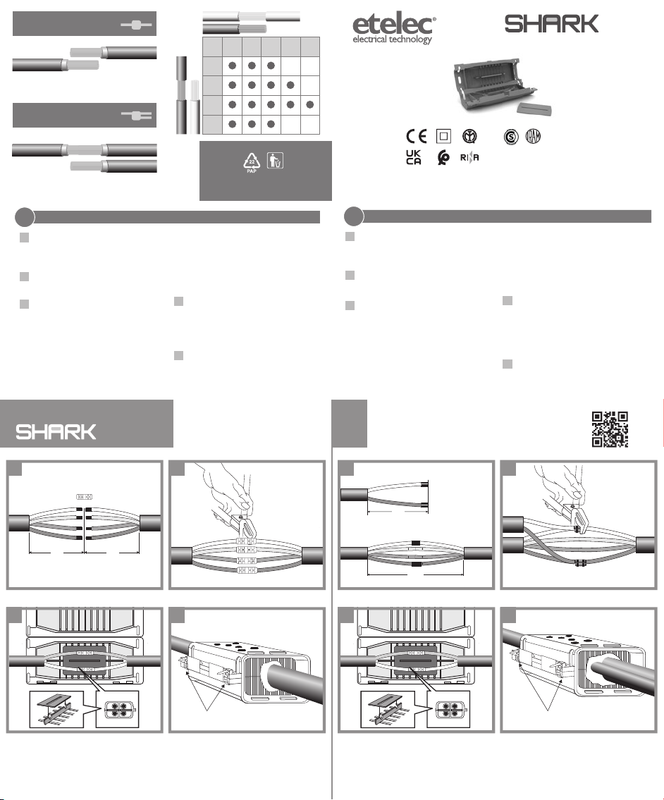
1. Remove the external sheath of cables as in
pict. 1 and strip each conductor according to
the type of connector used and to the type of
the joint (straight or branch).
2. Connect conductors by clamping connectors
by crimping or other suitable method,
depending on the kind of connector used.
3. For 3-core or 4-core cables: insert horizontal
separator between the couple of upper and
lower conductors.
Immerse the cable in the gel centering it on
the vertical separator and ensuring that the
ends of the horizontal separator (if present)
are tted in the two slits of the vertical
separator.
Ease the breaking of the breakable walls by
applying pressure on the cables near cable
entry and exit points.
For branch joints: pass the cores of the
branch cable that cross the main cable
through one of the two slits on the vertical
separator.
4. Snap-close the enclosure and check the gel
has displaced correctly, escaping the
enclosure and sealing around the cable at
each end.
Otherwise re-open the joint and insert some
piece of previously removed cable sheath.
5. Insert and fasten the cable ties supplied with
the kit into the side slits of the joint as per
Standard IEC 60364.
INSTALLATION INSTRUCTIONS
EN ISTRUZIONI DI MONTAGGIO
1. Sguainare i cavi per la lunghezza riportata in
g. 1 e spellare i singoli conduttori in funzione
del tipo di connettore utilizzato e del tipo di
giunzione da realizzare (linea o derivazione).
2. Eettuare la connessione dei cavi serrando i
connettori con metodo idoneo in funzione del
tipo di connettore utlizzato.
3. Per cavi tripolari o quadripolari: inserire
il separatore orizzontale tra le coppie di
conduttori superiori ed inferiori.
Immergere il cavo nel gel centrandolo sul
separatore verticale assicurandosi che le
estremità del separatore orizzontale (se
presente) vadano ad inserirsi nelle due asole
di quello verticale.
Facilitare la rottura delle paratie fratturabili,
applicando una pressione sui cavi in
corrispondenza dei punti di ingresso e di
uscita. Per giunzioni in derivazione: fare
passare i poli del cavo derivato che vanno ad
incrociare il cavo passante attraverso una delle
due asole.
4. Chiudere a scatto l’involucro e controllare
l’avvenuta fuoriuscita del gel dalle estremità
del giunto in corrispondenza dei punti di
ingresso e di uscita dei cavi.
In caso contrario riaprire il giunto ed
introdurre qualche spezzone di guaina
precedentemente asportata.
5. Inserire e stringere le due fascette fornite a
corredo nelle due asole alle estremità del
giunto in accordo alla Norma CEI 64-8.
IT
STRAIGHT JOINT
GIUNTO IN LINEA
BRANCH JOINT
GIUNTO IN DERIVAZIONE
3-4 × 4–16 mm2
2-4 × 4–16 mm
2-4 × 1,5–10 mm
2-4 x
4
6
10
16
4 6 102,5
mm21,5
2-4 x
IST-SH0416-12
cable ties / fascette
branch cable /cavo derivato
main cable / cavo passante
70
100
cable ties / fascette
1
3 4
1 2
3 4
21
5050
[ mm ][ mm ]

SH A R K 416
SH 0 416
- 20° C / + 90° C
IPX8
vázací pásky / bridas
odbočný kabel /cable derivado
hlavní kabel / cablo pasante
70
100
vázací pásky / bridas
3 4
1 2
3 4
21
EMPALME EN LÍNEA
PŘÍMÉ SPOJENÍ EMPALME EN DERIVACIÓN
ODBOČNÉ SPOJENÍ
MADE IN ITALY
etelec.com
0,6/1 kV
EN 50393
EN 60695-2-11
CEI 20-37/2-1
CEI 20-37/4
Zkontrolujte předpisy vaší obce
Consulta la normativa de tu municipio
PAPÍR / PAPEL
1. Pelar los cables para la longitud indicada en
gura 1 y los distintos conductores en función
del tipo de conector utilizado y del tipo de
conexión a realizar (línea o derivación).
2. Efectuar la conexión de los cables apretando los
conectores con método idóneo en función del
tipo de conector utilizado.
3. Para cables tripolares o cuadripolares:
insertar el separador horizontal entre los pares
de conductores superiores e inferiores.
Sumergir el cable en el gel centrándolo en el
separador vertical asegurándose que las
extremidades del separador horizontal (si
presente) se inserten en los dos ojales de
aquello vertical.
Facilitar la rotura de los mamparos fracturables,
aplicando presión sobre los cables en los
puntos de entrada y salida.
Para uniones en derivación: hacer pasar los
polos del cable derivado que van a cruzar el
cable a través de uno de los dos ojales.
4. Cerrar a presión el contenedor y controlar la
salida del gel de las extremidades del empalme
en correspondencia de los puntos de entrada
y salida de los cables. En caso contrario reabrir
el empalme e introducir algunos trozos de
funda anteriormente extraídos.
5. Insertar y apretar las dos bridas sujetacables
suministradas en apoyo en los dos ojales a las
extremidades del empalme de acuerdo con la
Norma CEI 64-8.
NÁVOD K INSTALACI INSTRUCCIONES DE MONTAJE
more
info
416
GEL INSULATED JOINT
®
Informace obsažené v tomto návodu jsou určeny pouze pro osoby s elektrotechnickou kvalikací.
Jejich účelem je vysvětlit správnou instalaci produktu. Správnost použití produktu v daných
podmínkách je na zvážení koncového uživatele.
La información contenida en las presentes instrucciones de instalación están destinadas a un uso
exclusivo de los instaladores instruidos a la realización de los sistemas eléctricos y tienen como
objetivo describir el método correcto de instalación para este producto. Es responsabilidad del
usuariodeterminar laidoneidaddelmétododeinstalacióncon respectoalascondicionesrealesen
el campo.
ES
CZ
ETELEC ITALIA S.p.A. Via D. De Roberto, 40 - 80143 Napoli Tel. +39 081 5846610
416
GEL INSULATED JOINT
®PŘÍMÉ SPOJENÍ
EMPALME EN LÍNEA
ODBOČNÉ SPOJENÍ
EMPALME EN DERIVACIÓN
3-4 × 4–16 mm2
2-4 × 4–16 mm
2-4 × 1,5–10 mm
2-4 x
4
6
10
16
4 6 102,5
mm21,5
2-4 x
1. Odstraňte izolaci kabelů a následně izolaci
každého vodiče v potřebné délce (obr. 1) dle typu
spojení (přímé nebo odbočné).
2. Propojte vodiče ve svorce buď krimpováním
nebo jinou vhodnou metodou v závislosti na
použité svorce.
3. Pro 3-žílové nebo 4-žílové kabely: vložte
horizontální oddělovač mezi vrchní a spodní
vodiče. Ponořte kabel do gelu a vycentrujte jej
na vertikálním oddělovači. Horizontální (pokud
byl použit) a vertikální oddělovač do sebe musí
zapadnout (obr. 3). Zatlačte na kabely na obou
koncích spojky, tak aby prolomily stěny.
Pro odbočné spojení: protáhněte vodič
odbočné větve otvorem ve vertikálním
oddělovači k hlavní větvi.
4. Uzavřete spojku a zkontrolujte, že gel byl
vytlačen na obou koncích okolo kabelu. Pokud
ne, znovu otevřete spojku a vložte např. kus
odstraněné izolace. To usnadní distribuci gelu
ve spojce.
5. Spojku zajistěte přiloženými stahovacími
pásky dle standardu IEC 60364.
5050
[ mm ] [ mm ]
Other etelec Cables And Connectors manuals


Popular Cables And Connectors manuals by other brands

Tektronix
Tektronix P6105A instruction manual

CommScope
CommScope SYSTIMAX VisiPatch CPC5562 instruction sheet

Camille Bauer
Camille Bauer PRKAB 560 operating instructions

Tecnosystemi
Tecnosystemi Smart Clima 11125135 user manual

Altronix
Altronix eBridge100RM installation guide

Philips
Philips SWV2205 Specifications


