etelec EVO 02D User manual
MADE IN ITALY
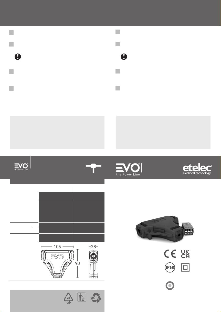
0,6/1 kV
EN 50393
IP68
EN 60529
EN 60695-2-11
CEI 20-37/2-1
CEI 20-37/4
Gel-insulated
Branch Joint
Giunto in derivazione
ad isolamento in gel
02D
etelec.com
105 28
90
ETELEC ITALIA S.p.A.
Via D. de Roberto, 40 - 80143 Napoli Italia - Tel. +39 081 5846610
Check your local waste regulations
Verica le disposizioni del tuo Comune
PAPER / CAR TA
02D
BRANCH JOINT
GIUNTO IN DERIVAZIONE
H05RN-F
H05RR-F
H05VV-F
FS18OR18
FROR
(A)FG16OM16
(A)FG16OR16
FG18OM16
RG16OR16
NYY-J
300/500 V0,6/1 kV
cross-section
sezione
cable
type /
tipo
di cavo type
tipo
U0/U
main / passante branch / derivato
diameter
diametro
dimensions
[mm]
dimensioni
[mm]
10 – 13 mm 6 – 8 mm
3 × 1,5 - 4 mm23 × 1,5 - 2,5 mm2
r.
f.
The information contained in these instructions is for use only by
installerstrained to makeelectrical power installations and is intended
to describe the correct method for installing this product.
It is user’sresponsibility to determine the suitabilityofthe installation
method in actual user eld conditions.
INSTALLATION INSTRUCTIONS
(see illustrations overleaf)
1. Remove the external sheath of the cables to be jointed for
30 mm and remove the insulation on each core for 8 mm.
2. Loosen the screws of the connector with a at-blade
screwdriver and place the wires into seats.
Respect polarity matching as marked
on connector.
Tighten all connector screws.
3. Immerse the jointing in the gel, placing the terminal block
centered inside device enclosure, exerting a slight pressure on
cables by thumbs in correspondence with the breakable walls.
4. Snap-close the enclosure.
The joint is ready to put line into service.
Fixing holes on the shell allow wall-mounting of the joint (plug
and screws not included).
Le informazioni contenute nelle presenti istruzioni di installazione
sono intese ad utilizzo esclusivo degli installatori istruiti alla
realizzazione degli impianti elettrici e mirano a descrivere il metodo
corretto per l’installazione di questo prodotto.È responsabilità
dell’utilizzatore determinare l’idoneità del metodo di installazione
rispetto alle condizioni reali sul campo.
ISTRUZIONI DI MONTAGGIO
(vedi illustrazioni sul retro)
1. Sguainare i cavi da giuntare per 30 mm e rimuovere l’isolante
sulle fasi mettendo a nudo i conduttori per 8 mm.
2. Allentare le viti del connettore con un giravite a taglio ed inserire
i conduttori nelle sedi.
Rispettare la corrispondenza delle polarità come
indicato sul connettore.
Serrare tutte le viti del connettore.
3. Immergere la giunzione nel gel posizionando il connettore al
centro del guscio stesso, esercitando una pressione in
corrispondenza delle paratie fratturabili.
4. Chiudere a scatto l’involucro.
Il giunto è pronto per la messa in servizio della linea.
Il giunto può essere ssato a muro per mezzo dei fori di
ssaggio sul guscio (tasselli e viti non inclusi).

MADE IN ITALY
0,6/1 kV
EN 50393
IP68
EN 60529
EN 60695-2-11
CEI 20-37/2-1
CEI 20-37/4
02D
etelec.com
105 28
90
ETELEC ITALIA S.p.A.
Via D. de Roberto, 40 - 80143 Napoli Italia - Tel. +39 081 5846610
Zkontrolujte předpisy vaší obce
Comprueba las normativas locales sobre residuos PAPÍR / PAPEL
02D
H05RN-F
H05RR-F
H05VV-F
FS18OR18
FROR
(A)FG16OM16
(A)FG16OR16
FG18OM16
RG16OR16
NYY-J
300/500 V0,6/1 kV
průřez vodiče
sección
typ
kabelu /
tipos
de cable
typ
tipo
U0/U
hlavní kabel / pasante odbočný kabel /derivado
průměr kabelu
diámetro
rozměry
[mm]
dimensiones
[mm]
10 – 13 mm 6 – 8 mm
3 × 1,5 - 4 mm23 × 1,5 - 2,5 mm2
r.
f.
La informacióncontenidaenlaspresentesinstruccionesdeinstalación
están destinadas a un uso exclusivo de los instaladores instruidos a la
realización de los sistemas eléctricos y tienen como objetivo describir
el método correcto de instalación para este producto.
Es responsabilidad del usuariodeterminarlaidoneidaddelmétodode
instalación con respecto a las condiciones reales en el campo.
Odbočná
gelová spojka
Dispositivo de conexión
de derivación con aislamiento en gel
ODBOČNÁ GELOVÁ SPOJKA
DISPOSITIVO DE CONEXIÓN DE DERIVACIÓN
INSTRUCCIONES DE MONTAJE
(véase ilustraciones en la parte posterior)
1. Pelar los cables para empalmar de 30 mm y remover el aislante
sobre las fases exponiendo los conductores de 8 mm.
2. Aojar los tornillos del conector con un destornillador de punta
plana e insertar los cables en los asientos.
Respetar la correspondencia de las polaridades
como se indica en el conector.
Apretar todos los tornillos del conector.
3. Sumergir el conjunto en el gel, posicionando el conector en el
centro de la carcasa del dispositivo, ejerciendo una ligera presión
en correspondencia de los mamparos fracturables.
4. Cerrar a presión la carcasa. El dispositivo está listo para la puesta
en servicio de la línea. El dispositivo puede ser jado a la pared
mediante oricios de jación en la carcasa (tacos y tornillos no
incluidos).
Informace obsažené v tomto návodu jsou určeny pouze pro osoby s
elektrotechnickou kvalikací. Jejich účelem je vysvětlit správnou
instalaci produktu. Správnost použití produktu v daných podmínkách
je na zvážení koncového uživatele.
NÁVOD K INSTALACI
(viz. obrazová příloha)
1. Odstraňte 30 mm izolace kabelů, které mají být propojeny.
Poté odstraňte 8 mm izolace z každého vodiče.
2. Uvolněte šroubky na svorce pomocí plochého šroubováku a
vložte vodiče do svorky.
POZOR! Dodržujte vyznačenou polaritu.
Utáhněte šroubky.
3. Ponořte vytvořený spoj do gelu, tak by byl ve středu spojky.
Zatlačte palci na kabely v prostoru pružných průchodek.
4. Zaklapněte kryt a zařízení je připraveno k provozu.
Otvory na šrouby v plášti spojky umožní její případné upevnění
na stěnu (spojovací materiál není součástí balení)

IST-EV202D-10
4
3
2
Cu-Cu
Al-Al
Cu-Al
[dim. in mm]
30
8
8
30
30
8
1
02D
BRANCH CONNECTING DEVICE
DISPOSITIVO DI CONNESSIONE
IN DERIVAZIONE
video
Other etelec Cables And Connectors manuals


Popular Cables And Connectors manuals by other brands


Nitho
Nitho NSW-JCOG-K quick start guide

System Q
System Q CAB705 manual

PCB Piezotronics
PCB Piezotronics IMI SENSORS 522SPBZ Installation and operating manual

Extron electronics
Extron electronics MHR-5STP-2 Specifications

PCB Piezotronics
PCB Piezotronics 010D30 Installation and operating manual

PCB Piezotronics
PCB Piezotronics 045M29 Installation and operating manual