ETG ETG6900 Operator's manual

www.rbr.co.kr / www.eurotron.co.kr
Tel.: 02-837-6974
Fax.: 02-859-2059
Email: [email protected]
Fixed version
세 일 국 제 무 역
USER INSTRUCTION MANUAL
ETG 6900
NH3 LASER ANALYZER
서울특별시 구로구 공원로 81
3층 (구로동, 엘림빌딩)

Versione mark_2
2
SUMMARY
1 OverView ....................................................................................................................................... 4
1.1 ETG 6900................................................................................................................................. 4
1.1.1 block diagram of the whole system................................................................................... 4
1.1.2 block diagram of the pneumatic scheme........................................................................... 5
1.1.3 Overview system.............................................................................................................. 5
2 Installation ..................................................................................................................................... 7
2.1 electrical and pneumatic connection ........................................................................................ 7
3 Measurement Graph....................................................................................................................... 9
4 Set up the analyser ....................................................................................................................... 10
5 Datalog and download ................................................................................................................. 12
5.1 Datalog................................................................................................................................. 12
5.2 Download ............................................................................................................................. 13
6 Calibration ................................................................................................................................... 16
6.1 Zero Calibration..................................................................................................................... 17
6.2 Span Calibration.................................................................................................................... 17
7 Maintenance ................................................................................................................................ 18
7.1 ETG 6900Maintenance........................................................................................................... 18
7.2 ETG GAS LASER MAINTENANCE AND TROUBLE SHOOTING...................................................... 18
7.2.1 Warnings....................................................................................................................... 18
7.2.2 Maintenance ................................................................................................................. 19
7.2.3 ANNEX........................................................................................................................... 20

Versione mark_2
3
This alert identifies hazards that should be considered to prevent damage to property and
people and the analyzer itself.
This symbol indicates information that is useful for the system

Versione mark_2
4
1 OverView
1.1ETG 6900
1.1.1 block diagram of the whole system
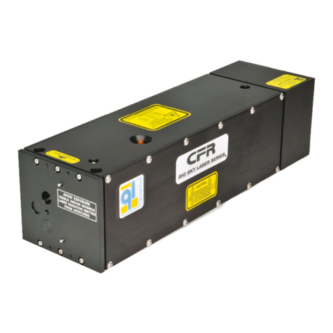
NH3 Ammonia Analyzer
• Ammonia gas analyzer (NH3) based on laser technology.
• Sample to be analyzed at room temperature
• Suitable for 19" rack mounting
• Minimum standard range 0-100 ppm
• Maximum standard range 0-1000 ppm
• Detection limit 4 ppm
• Signal Output 4-20 mA

Versione mark_2
5
1.1.2 block diagram of the pneumatic scheme
1.1.3 Overview system

Versione mark_2
6

Versione mark_2
7
2Installation
Dear Customers,
Thank you for choosing ETG for your analysis system.
The NH3 GAS ANALYSER is designed for the continuous measurement of NH3. This system has been
designed with the intention to provide a system of high efficiency but at the same time intended for a user
even low knowledge.
Thanks to the software developed by ETG, the user is able to carry out a high performance and versatile
analysis in a few minutes.
The analyser is ready to use.
Plug the charger and connect it to your power plug.
Switch on “charge”: if the led on the charger is green, the analyser is fully charged; if is red, wait for green
light.
Please read this manual carefully.
2.1 electrical and pneumatic connection
the procedure is simple:
•Open the ETG6900 case.
•Inside you will find a terminal box of the following type:

Versione mark_2
8
•Connect the analog signal of the 4-20mA output of the NH3
•Then exit with the cables from the hole provided in the ETG6900 case (1)
•Make the pneumatic connections (2),(3)
•Connect the LAN cable (4), connect to the network with DHCP.
•Connect the power supply by connecting a cable to the rear socket of the ETG6900 (5)

Versione mark_2
9
3Measurement Graph
The program will displays graph, in real-time measurement. The origin of the axis time is made to coincide
with the beginning of the measurement session. You will see real time data in the upper side of the window
(“Last Measure”).
In the same screen of the software indicates the presence of any alarms with a reference code (that’s need
to be communicated to ETG for troubleshooting)
Fig. Main screen
If you click on "Reset Graph", the software, after asking for confirmation via a pop-up, start a new session
of measurement to a new origin of the time axis.
If you’re sampling ambient air remember to activate the internal pump
If you’re sampling gas from a pressure sampling point, be sure that this one it’s not higher than
100mbars! (in that case don’t activate the pump)

Versione mark_2
10
4Set up the analyser
From the main screen (Fig. Main screen), tap on “Control” then, it will open the following screen:
now click on “Settings”

Versione mark_2
11
Here you can change the parameters of data acquisition from the laser sensor.
Setting
Description
Limits
Integration Time
The sensor sends one value per second. If longer
measurement periods can be accepted, the integration
time can be increased. This reduces the noise of the
measurement but increases the reaction time when
changing the gas concentration. Note that this is just a
parameter in the interface and does not affect the sensor.
1s < Integration Time < 120s

Versione mark_2
12
5Datalog and download
5.1 Datalog
From “Settings” menu you can activate or deactivate the datalog.
From the main screen (Fig. Main screen), tap on “Control” then, it will open the following screen:
then click on “Log” and it will open the following screen:

Versione mark_2
13
Tapping “Switch” you can activate o deactivate it.
You can set a different interval for data acquisition, default is 10 seconds (data is stored every 10 seconds).
5.2 Download
Remember to deactivate the datalog before the download
To download the data, proceed as follow:
•if ETG6900 is connected to the network via DHCP, find its address using an appropriate program, it
should be similar to 192.168.X.X
•else use the address you set
•therefore, remotely use a PC with VNC viewer software to access the instrument. You should see a
replica of the ETG6900 screen.
Then:
➢Click the button on your keyboard
➢Select with your mouse Start/Programs/Windows Explorer

Versione mark_2
14
➢Double click on “FlashDisk”
➢In the folder “Log” you’ll find the sub-folders named by the “log’s date”;select which you’re
interested to and with a right-click of your mouse select “copy”
To avoid risk of memory’s saturation, you can press “cut” to delete the files from internal storage.
You can even select the entire “Log” folder
➢With the “UP” button browse back to the folder “My Device”.

Versione mark_2
15
➢Double click on “USB HD”
➢Paste your log’s files pressing the right-click and selecting “Paste”
➢Done. You can remove all USB devices connected.

Versione mark_2
16
6Calibration
From the main screen (Fig. Main screen), tap on “Calibration” then, it will open the following screen:
The user has the ability to set the “offset” and the “span” of the instrument (remember, the laser sensor
is already was pre-calibrated and does not require frequent calibration).
Before start the zero or span calibration, you will be prompted to insert the "span value" of the bottle you
have: click on “configure” in the calibration menu from the main screen.

Versione mark_2
17
Insert the value of concentration reported on the cylinder. After entering and pressing "OK" the software
will record this value and is ready to perform the calibration of the instrument.
Be sure to insert the correct value of "Span Value" or calibration make it unreliable the instrument!
6.1 Zero Calibration
The zero calibration is necessary to set the offset of the analyzer. Depend if you have the internal solenoid
for calibration, after clicking on “Start” in Zero calibration, the analyser will ask you to conform or
remember to open the pneumatic valve of the calibration in your system. After confirming the opening
(manual or electronic) of the valve calibration, you will see that the graph is now showing not the sampling
gas but the calibration gas . When the data has stabilized to a value that is acceptable, and after passing a
sufficient time for stabilization of the measurement (not adjustable by user), if the user clicking on "Save
Calibration" will set that value as the new value zero of the sensor. Click “Stop” to abort the procedure.
6.2 Span Calibration
The procedure is the same as the calibration of zero, save that the value recorded by the analyzer it will be
used for Span compensation in the measurement.
Since both the calibrations (Zero and Span) are used for the compensation of the measured data, it is
recommended to perform always both calibrations together, in order to update them both and to
obtain a precise measurement.

Versione mark_2
18
7Maintenance
7.1 ETG 6900Maintenance
Check
Frequency
Methodology
Solution
Sampling Pump
6 months
Verify if there are aspiration on sample line
Contact ETG
be sure that you’re in sample mode and
not in calibration!
Inline Filter
Every month
Verify if there are dirt inside the filter (inside
the analyser)
Change the filter.
Contact ETG for
replacement.
Zero Calibration
Every month
Make it flow N2 inside the instrument (follow
calibration’s procedure) and verify the response
of instrument around 0 ppm.
Zero- calibrate the
analyser.
Span Calibration
6 months
Make it flow Span Gas Cylinder inside the
instrument (follow calibration’s procedure) and
verify the response of the instrument around
the concentration of cylinder.
Span- calibrate the
analyser.
7.2 ETG GAS LASER MAINTENANCE AND TROUBLE SHOOTING
7.2.1 Warnings
The laser gas sensor modules will not require routine maintenance when the installation and operation
instructions described in this document are carefully applied. The surface of the instrument can be cleaned
with a soft tissue and the use of isopropyl alcohol. Any gas filtration and conditioning equipment must be
checked and replaced periodically according to the manual specifications.
If the measurement cell gets contaminated or damaged, please contact ETG RISORSE E TECNOLOGIA for cell
maintenance and replacements. As technical training is necessary for this procedure, we recommend
setting up a system exchange program. Please contact ETG RISORSE E TECNOLOGIA for details.
In case of problems, recheck all the recommendations presented in this document and be sure they have
been followed and fully applied. If the observed problems persist, contact your ETG Risorse e Tecnologia
sales person.
It is important that this device is serviced only by adequately trained and
qualified personnel.
This instrument contains electronic components that might be damaged by static
electricity. The device cover should never be removed as it might damage the optics
and/or electronics.

Versione mark_2
19
ETG gas sensor modules contain metal and elastomeric sealing parts. The customer is
responsible for checking the compatibility of those materials with the gas applied to the
device. Not observing these recommendations might lead to personal injury or death.
It is recommended that the user checks the device regularly to ensure that it is leak-
free.
Sealings may change their characteristics with age, exposure to process gas,
temperature
and pressure.
If it is necessary to remove the device from the system, unplug the electrical power
before
any other manipulation.
Before removing the device from the system, purge thoroughly with a dry inert gas such
as
Nitrogen before disconnecting the gas fittings. Ensure that the piping is de-pressurized.
Failure to correctly purge and de-pressurize the device could result in fire, explosion, or
severe injury.
7.2.2 Maintenance
After verifying the factors above, follow the troubleshooting procedures outlined here below:
Problem
Possible Cause
Solution
No signal / No value output
No power supply or wrong
polarity
Check wiring
Measurement cell
temperature does not
stabilize at desired
temperature
Wrong polarity on heater power
supply
Check wiring
The heating time is > 30 min
(when started at 25°C / 77°F,
ambient temperature)
The power supply used for the
heater
is not able to supply up to 8 A
Check max current of used power
supply or change power supply
No reaction when target gas is
flowed in
Condensation in system
Flow with dry and dust-free air in
the Gas inlet and in the Purge
inlet for at least 15 min
Every 10 or 11 acquisition
points
the time between points is
longer
When the target gas
concentration is below a certain
limit, the sensor has an internal
check which lasts longer
(around 2s)
Flow with higher amount of
target gas
The T90 is longer than
expected
The flow is lower as 3 l/min
Increase the flow rate

Versione mark_2
20
7.2.3 ANNEX
N°
E/W
Message
Action/Solution
Detailed Explanation
19
E
Unexpected error /watchdog)
Reboot (15 s)
Check Communication
Contact Service
Check sensor connectivity
239
E
End Of Life
Soon Sensor will no longer work
The sensor will soon be out of service
240
E
Optical Head’s temperature
out of range
Check for additional errors
(249) Bring the ambient system
temperature within the
specified range. Try to mount
the system horizontally.
Check if ambient temperature is within
specified range See also error code 248 &
252. OK (temperature within range), there
is a system failure: service required.
241
E
Laser driver failure. Sensor
not measuring.
Check for additional errors
(250)
Service required
Check if ambient temperature is within
specified range See also error code 248 &
252. OK (temperature within range), there
is a system failure: service required.
242
E
Laser driver failure. Sensor
not measuring.
Check for other errors (251)
Service required Policy not yet defined.
Reset the sensor.
243
E
Low power on the photodiode
Check for condensation OR
Service required
Check that the conditions of use do not
cause condensation. If this is not the
case, service is required.
244
W
Low power on t he
photodiode.
Cleaning of optics required.
OR see error 250 in Manual
Sensor is functioning but with
compromised performance due to
misaligned optics, dirt or
condensation. Service required soon.
245
W
Power on photodiode too
high.
Service required
Sensor functionality compromised Please
call service
246
W
Laser temperature
compensation executed
(system restarting)
Aging of the laser is compensated until it
reached EOL state.
247
E
Laser current compensation
limit reached
Service required.
EOL is reached. Call service immediately.
248
E
Cell Temperature of out safe
range.
out of range --> switch off
sensor AND gas flow
Avoid condensation
SENSOR MIGHT BE HOT: DO NOT TOUCH
WITH BARE HANDS
The temperature limits are set between
(H) Version: {-40°C.. 200°C}, Sensor not
measuring.
(A) Version: {50°C..
100°C}.
Check ambient temperature.
Ensure proper venting
Actively monitor ambient conditions
249
E
System Temperature out of
range Sensor not measuring.
Bring the ambient system
temperature
within the specified range
Check ambient temperature.
Ensure proper venting. Actively monitor
ambient conditions
out of range --> switch off sensor AND gas
flow
250
E
Laser driver failure. Sensor
not measuring
Service required
Check if ambient temperature is
within specified range.
See also error code 251 & 252 in the
user manual. If OK (temperature in
range), there is a system failure:
service required.
Table of contents
