ETH-messtechnik DRBK User manual

tel. +49 (0)79 72 93 10-0
hagstrasse 10 . D-74417 gschwend
English
messtechnik
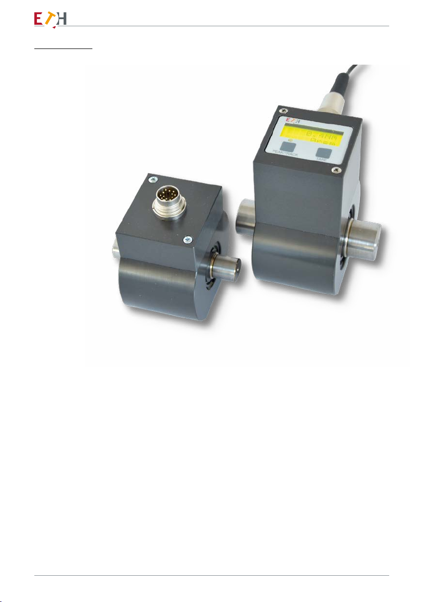
Torque Sensor
DRBK / DRBK-n
DRBK-A
Operating Instructions

messtechnik
2
© ETH messtechnik gmbh
This operator manual is not a quality agree-
ment or durability guarantee as set out in
Section 443 of the German Civil Code.
Specification changes, typing and
printing errors reserved.

messtechnik
3
Inhalt
Important instructions: ...................................................................................................4
1. Introduction................................................................................................................. 5
2. Field of application and application instructions.........................................................5
3. Structure and mode of operation................................................................................ 6
3.1 Torque Shaft.........................................................................................................6
3.2 Case .....................................................................................................................6
3.3 Measurement ......................................................................................................6
3.4 Disturbances and their compensation.................................................................7
4. Conditions on location.................................................................................................8
4.1 Ambient temperature..........................................................................................8
4.2 Moisture and dust................................................................................................8
4.3 Chemical effects................................................................................................... 8
4.4 Deposits ...............................................................................................................8
5. Mechanical installation................................................................................................9
5.1 Precautions when assembling .............................................................................9
5.2 General assembly guidelines ...............................................................................9
6. Structure of the measurement chain ........................................................................10
7. Connection ................................................................................................................11
7.1 Hints for connection ..........................................................................................12
7.2 Connector ..........................................................................................................12
7.3 Pinout of the connector.....................................................................................12
7.4 Extension of cable..............................................................................................12
8. Pinout ........................................................................................................................13
9. Output .......................................................................................................................14
10. Functions of the display (at DRBK-A).......................................................................15
10. Recalibration............................................................................................................16
11. Disposal ...................................................................................................................16
13. Datasheet ................................................................................................................17
13.1 Technical specifications....................................................................................18
13.2 Mechanical dimensions DRBK..........................................................................19
13.3 Sizes DRBK........................................................................................................19
13.4 Mechanical dimensions DRBK-A ......................................................................20
13.5 Sizes DRBK-A ....................................................................................................20
13.6 Mechanical values and load limits DRBK + DRBK-A ........................................21

messtechnik
4
Important instructions:
The torque transducers of the DRBK-A series can be used as machine elements
(e.g. test bench). In the case of mass-critical applications, the installation positi-
on of the drive and measurement side must be taken into account.
Please note that the transducers are not designed with the safety factors (2...20)
customary in machine designs in favor of high measurement sensitivity.
Pay particular attention to the specified overload factors.
Where people and property could be injured in the event of breakage, the user
must take appropriate safety measures (e.g. covers, overload protection) (obser-
ve the relevant accident prevention regulations!).
The torque transducer is not approved for use in hazardous areas.
If the transducer is opened or dismantled within the warranty period, the war-
ranty claim becomes void.
The transducer may only be opened by qualified personnel.

messtechnik
5
1. Introduction
Torque transducers measure torques in Nm.
2. Field of application and application instructions
The torque transducers measure both right-hand and left-hand loads. With a
right-hand load, the signal direction is positive. The nameplate provides informa-
tion about the final value of the measuring range.
The torque transducers measure dynamic moments just as precisely as static
torques. Here, the low masses and the high torsional rigidity are of particular
advantage.
Note the signal rise of the transducer specified in the data sheet.
The torque transducers are maintenance-free due to their non-contact measure-
ment signal transmission. Your electrical measurement signals can be transmit-
ted to remote measurement stations and displayed, registered, processed and
used for control and regulation tasks.
As a precision measuring device, the torque transducers require careful handling
during transport and assembly, since impacts or falls can damage the transducer.
Torque peaks in excess of the permissible overload can lead to the destruction
of the torsion shaft. Where such peaks cannot be ruled out with certainty, they
must be intercepted.
The limits for the permissible mechanical, thermal and electrical stresses are
listed in the data sheet. It is imperative that they are complied with. Please take
this into account when planning the measuring arrangement, during installation
and finally during operation.

Channel A
(PIN G)
messtechnik
6
3. Structure and mode of operation
3.1 Torque Shaft
The torsion shaft is made of hardened steel. The torque-proportional torsion of
the torsion shaft within its elastic range is evaluated with strain gauges (DMS)
applied to it. The strain gauges are arranged in a Wheatstone bridge circuit. The
non-positive connection takes place via suitable couplings on the cylindrical shaft
ends.
Optionally, the torsion shaft of the DRBK can be equipped with a speed measure-
ment (see data sheet).
3.2 Case
The torque transducer housings are made of high-strength aluminum and the
surface is hard-anodized for protection. The torsion shaft is mounted twice in the
housing via deep groove ball bearings. The transducer is mechanically fastened
via threaded holes on the bottom of the housing. An evaluation electronics for
torque and speed is mounted on the housing.
3.3 Measurement
The torsion shaft and thus the DMS are elastically deformed by the torsional
force. The strain gages change their ohmic resistance in proportion to their
change in length. The downstream electronics transmit the measurement signal
optically frequency-modulated to the external electronics.
The conversion in the external electronics into the two output signals voltage/
current takes place in proportion to the change in frequency. These are available
for further evaluation.
A square-wave signal with 60 pulses/revolution is available at the speed output

messtechnik
7
3.4 Disturbances and their compensation
Avoid bending, axial and radial forces. When you have problems with this, use
ETH clutches.
To connect the transducer to a measurement unit you need a shielded cable.
The transducers are EMC-tested and are complying with
EN 55011:1998 + A1:1999 + A2:2002
EN 61326-1:2006-05 and
EN 61000-6-2:2005.

messtechnik
8
4. Conditions on location
4.1 Ambient temperature
For best results, the device must be operated within the nominal temperature
range. The best operating conditions are constant and, if necessary, slowly
changing temperatures. The specified temperature errors apply if the tempera-
ture does not change faster than 5K/h. One-sided thermal radiation or cooling
should be avoided and appropriate technical preventive measures taken, if
necessary.
4.2 Moisture and dust
The torque transducers comply with protection type rating IP40 as per DIN
40050.
Note: There should be no moisture inside the transducer connector
4.3 Chemical effects
The torque transducers are not protected against chemical effects. They must
not be used in caustic or corrosive environments.
4.4 Deposits
Dirt, dust or other foreign substances should not accumulate so that they can
enter the bearing or the connectors.

messtechnik
9
5. Mechanical installation
5.1 Precautions when assembling
• Handle transducer carefully.
• Important note:
When installing the couplings, do not overload the transducer,
not even temporarily.
It is strongly recommended to remove the transducer before
mounting connect electrically and the torque signal with too
monitor in order not to exceed the measuring range!
• Misalignments in the axial and radial directions must be avoided.
The axis offset should be max. 50% of the permissible values of the
coupling used (axial, angular and lateral misalignment) be.
Please refer to the data sheet for your coupling for this data.
• A good electrical connection of the housing to grounded parts
must be observed.
5.2 General assembly guidelines
The drive and transducer sides should not be swapped, otherwise measure-
ments (readings) will be invalidated during accelerations, for example.
When reading the device label, the drive side is on the right and the transducer
side on the left of the transducer. There is a small cavity in the cover on the
measurement side.
Flexural, axial and radial forces are disturbances that cause incorrect
measurements.
Be careful with the thermal expansion of the assembly.

messtechnik
10
6. Structure of the measurement chain
In order to be able to measure with the transducer, a complete measurement
chain must be set up.
This consists of:
• torque transducer
• connection cable
We recommend using our ETH cables.
They are optimized in design and shielding.
• Supply and evaluation device (e.g. PLC)
A supply unit is necessary to supply the transducer with the necessary operating
voltage. The transducer includes the complete measuring amplifier, so that no
additional amplifier is necessary. The measuring signal can be further processed
directly (e.g. PC) or displayed and evaluated with supply and evaluation devices.
messtechnik
11
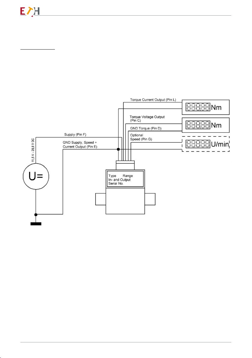
7. Connection
Connection of a torque transducer with a 12-pin connector

messtechnik
12
7.1 Hints for connection
Electric and magnetic fields cause interference with the measuring signal. This
interference is mainly caused by power cords, relays or motors installed nearby.
Besides these, interference can be caused by multiple grounding of the measure-
ment chain on more than one point.
Pay attention to the following:
• Use only shielded cables with low capacitance
(like our measuring cables).
• Connect supply voltage correctly (no reverse polarity protection).
• Measuring cables shouldn’t be nearby high voltage or control cables.
• Magnetic radiation from transformers, motors or relays
must be avoided.
• Don’t ground transducer and display unit multiple.
• Connect all devices of the measurement chain to the same ground.
7.2 Connector
The transducer is equipped with a 12 pin fitted connector type Binder.
7.3 Pinout of the connector
The pinout of the connector is showed on the next page.
7.4 Extension of cable
Extension cables must be shielded and low-capacitance.
We recommend using the cables we offer that meet these requirements.
In the case of cable extensions, care must be taken to ensure a perfect connec-
tion and good insulation. It is important to ensure that the cable cross-section is
large enough to ensure sufficient supply voltage at the transducer.
Recalibration is not necessary when the cable is extended.
If the cable has to bridge a longer distance, we recommend using the current
output.

messtechnik
13
(Connection on the transducer seen from the front)
Pin
Standard cable
AK12.4
Colour
Robot cable
AK12.5
Colour
Pinout DRBK
A Green Black message ready
B Red / Blue Red NC
C Yellow Brown moment voltage output
D White White moment voltage mass
EGrey Yellow supply + speed + current ground
F Pink Purple supply +11…28V
G Grey / Pink Green speed output
H Purple Pink memory chip
J Black Grey NC
KRed Grey/Pink NC
L Brown Blue/Red moment current output
M Blue Blue NC
8. Pinout
• Standard measuring cable AK12.4
• Robot cable AK12.5
Connector: 12 pin

messtechnik
14
9. Output
The transducer`s output is a proportional voltage of 0 - ±5V and a current of
10 - ±8mA.
With clockwise torque the output is positive; with counter clockwise torque the
output voltage is negative.
The outputs for rotation speed and angle
measurement have an open collector
stage, with an internal 10 KΩ pull up resi-
stor in series with a diode. See schematic
below.
With this circuit you can measure speed
of more than 15,000 RPM and with a
cable of up to 33 ft.
The signal level of the circuit on the left
hand side is suitable for opto couplers,
frequency counters, oscilloscopes and
for (H)CMOS logic. If you need standard
TTL levels you can add the circuit on the
right hand side.
The ‘ready‘ signal is activated as soon
as the supply voltage is within the permitted voltage range and the overvoltage
protection has not been activated.
The voltage level on the ‘ready’ output is equal to the applied supply voltage.
The output can be loaded with max. 100mA.

messtechnik
15
10. Functions of the display (at DRBK-A)
The displayed torque is always shown in 4 digits. For example, with a nominal
torque of 200 Nm, a value is displayed as „199.2Nm“. The torque is updated
every 100ms.
The speed is represented as an integer. The valid range is between 0 and 32000
RPM.
The update occurs every second.
In standard the display is in track mode (LED off).
To change the measuring mode, press the „PEAK / TRACK“ button. If the peak
mode is active, the LED below the display lights up. The peak mode shows the
respectively applied peak torque in right-hand load. It is only available for values
greater than 5% of the full scale value in right-hand load. The current torque is
displayed for values that are smaller or with left-hand load.
With the „TARE“ key, the zero point can be reset in track mode. However, this
function is only available if the torque is less than 5% of the end value of the
measuring range.
In the peak mode, the „TARE“ key has the function of deleting the displayed peak
value.

messtechnik
16
10. Recalibration
Regardless of usage, the sensor must be calibrated after the period specified by
ETH - every 2 years by default
(see certificate and sticker sensor).
We also carry out a complete check (e.g. wearing parts).
To ensure that the calibration can be carried out quickly, we recommend making
an appointment before returning the device.
11. Disposal
The transducer can be returned to us free of charge for disposal, complete
with the measuring cable. As soon as this is packed by you, send a message to
sales@eth-messtechnik.de, we will then commission our parcel service to collect
it.
Unfortunately, we cannot accept parcels sent to us without prior notice.
messtechnik
17
13. Datasheet
Hagstraße 10 · 74417
Gschwend
www.eth-messtechnik.de
Torque Transducer
DRBK + DRBK-A
Torque ranges from 0,5 to 1000 Nm
Features
• Low-Cost Torque transducer
• Current output and voltage output
• Very short
• Measurement accuracy: ≤ 0.5% of full scale
• Contactless transfer of measurement signal
• Proven strain gage technology
• Integrated signal amplifier
• Single power supply
• wide range of applications
• Optional speed measurement
Extra Features DRBK-A
• Simultaneous speed/torque indication
• 4-segment display with sign
• Peak mode (clockwise only)
• Indication area on LCD display 30 x 11 mm
• Speed indication updated 1x sample/second
• Torque updated 1,000 samples/second
The Series DRBK torque transducers are suitable for
lab and industrial applications because of their small
size and multiple mounting options.
As supply voltage and output signal are transmitted
without contact, the device can operate continuously
with low wear and nomaintenance.
These transducers are also available with speed mea-
surement for a host of applications.
Series DRBK-A torque transducers are custom made
for applications where an extra analyzer should not
be used or is not needed.
Production monitoring data can be clearly displayed
at very small cost!
DB_DRBK/DRBK-A_EN_Rev03 07.11.2022

messtechnik
18
Technical Specifications: DRBK + DRBK-A
Supply voltage: 11,5 to 28,8 V DC
Current consumption: DRBK approx. 200 mA / DRBK-A approx. 250 mA
Rise time 10-90 %: 1 ms
Limit frequency –3 dB: 1 kHz
Voltage output:
Internal resistance:
0 to ± 5 V
100 Ω
Current output: 10 ± 8 mA Burden max 500 Ω
Ripple: < 100 mVss
Nonlinearity: < 0,3 %
Hysteresis: < 0,3 %
Deviation at zero point: ≤ ± 100 mV / ± 200 µA
Max. measurement error 0,5 % (FS / of full scale)
Operating temperature: 0 - 60 °C
Compensated temperature range: 5 - 45 °C
Temperature error
Zero point:
Sensitivity:
0,05 % / K
0,02 % / K
Mechanical overload: 100 %
Internal protection: IP40
Connection: 12pin- connector
EMV Immunity for interference (DIN EN 61326-1 / EN 61000-6 ) *1
Enclosure
HF line interference
150 kHz - 80 MHz (AM)
Severity
3 V
Criterion
A
(ESD) Electrostatic discharge Air 8 kV
Contact 4 kV
A
A
Enclosure
Electromagnetic Field
80 MHz - 1000 MHz (AM)
80 MHz - 2700 MHz (AM)
10 V/m
10 V/m
A
A
Leads - Connection Cable
Burst (fast transients) 2 kV A
Surge voltage (Surge) 1 kV B
Interference Emission (EN 61326-1 / EN 55011)
Disturbance Voltage
(Electromagnetic Disturbances)
Radiated Emission
(Electromagnetic Disruption axis)
-
-
Class B (150 kHz - 30 MHz)
Class B (30 MHz - 1000 MHz)
Speed Option (n) only DRBK *2
max. rev.: up to 10 000 min -1 *3
Output: Open-Collector
Internal pull up: 4,7 kΩ (5 V level)
External pull up: 24 V max / 20 mA
Pulses/rev.: 60
*1 Severity / Criterion: industrial environment;
Cable lenght ≤ 30m.
Application not outside buildings.
*2 standard on DRBK-A
*3 by proper external connections til speed max.
13.1 Technical specifications

messtechnik
19
Mechanical Dimensions DRBK
Type: 0 I II III
Torque Ranges: (Nm) | 0,5 | 1 | 2 | | 5 | 10 | 20 | | 50 | 100 | 200 | | 500 | 1000 |
Dimensions:
L (mm) 66 80 90 120
Ø B1 (mm) 45 70 75 105
B2 (mm) 45 53 53 76
H (mm) 56 72 77,5 97,5
H1 ± 0,05 (mm) 18 28 30 40
Ø D g6 (mm) 6 15 24 40
L1 (mm) 42 48 52 65
L2 (mm) 10 15 18 26
A1 (mm) 33 39 42 50
A2 (mm) 20 31 35 55
MM3 x 5 deep M4 x 6 deep M4 x 6 deep M5 x 10 deep
General tolerances DIN 2768 - m
Weight approx.: (g) 230 550 850 2450
Speed max.: (1/min ) 20000 18000 16000 9000
Sizes DRBK
13.2 Mechanical dimensions DRBK
13.3 Sizes DRBK

messtechnik
20
Mechanical Dimensions DRBK-A
Sizes 0 I II III
Torque Ranges: (Nm) | 0,5 | 1 | 2 | | 5 | 10 | 20 | | 50 | 100 | 200 | | 500 | 1000 |
Dimensions:
L (mm) 66 80 90 120
Ø B1 (mm) 45 70 75 105
B2 (mm) 54 53 53 76
H (mm) 90 100 106 122
H1 ± 0,05 (mm) 18 28 30 40
Ø D g6 (mm) 6 15 24 40
L1 (mm) 42 48 52 65
L2 (mm) 10 15 18 26
L3 (mm) 51 48 52 65
A1 (mm) 33 39 42 50
A2 (mm) 20 31 35 55
A3 (mm) 22 ---
MM3 x 5 deep M4 x 6 deep M4 x 6 deep M5 x 10 deep
General tolerances DIN 2768 - m
Weight approx.: (g) 310 610 910 2530
Speed max. (min-1 ) 20000 18000 16000 9000
Sizes DRBK-A
13.4 Mechanical dimensions DRBK-A
13.5 Sizes DRBK-A
This manual suits for next models
2
Table of contents


