Ethos IS100 User manual

Page 1 of 2
Specifications / Installation instructions
Freestanding Models: Genesis, Aquos, Phoenix
( E ffective 1 Jan 2017 )
IMPORTANT
It is the responsibility of the installer to ensure that the installation of this appliance complies with AS/NZS 2918:2001
Supplied: Ethos freestanding fire
Flue kit: 3 x 1200 130mm SS flue
1 x 600 130mm SS flue
2 x 200 x 1200 liners ( black )
1 x 200 x 1200 liner ( galv )
1 x Revolving cowl & cone
1 x Ceiling plate ( black )
Not included in kit: Flashing
Hearth / Floor protector
Screws / Rivets
Dynabolts
Fire cement
Mounting rails
Flue kit: Ethos wood fires must be fitted with the Ethos factory flue kit as this has been specifically designed to
achieve optimum performance of the unit. It must be a minimum of 4.2 mtrs.
note: It is essential that the 130mm stainless steelflue is well sealed & riveted it must also be securely
fitted & sealed into the exhaust spigot of the fire using stainless steel rivets or screws.
Shielding: The Ethos Genesis / Aquos / Phoenix wood fires do not require additional shielding, however reduced
clearances may be obtained using approved heat resistant material.
( r ef: AS/NZS 2918: 2001 )
Seismic restraint: Use 2 x 6mm dynabolts or similar, two holes are provided in the rearof the firebox pedestal or feet
for this purpose.
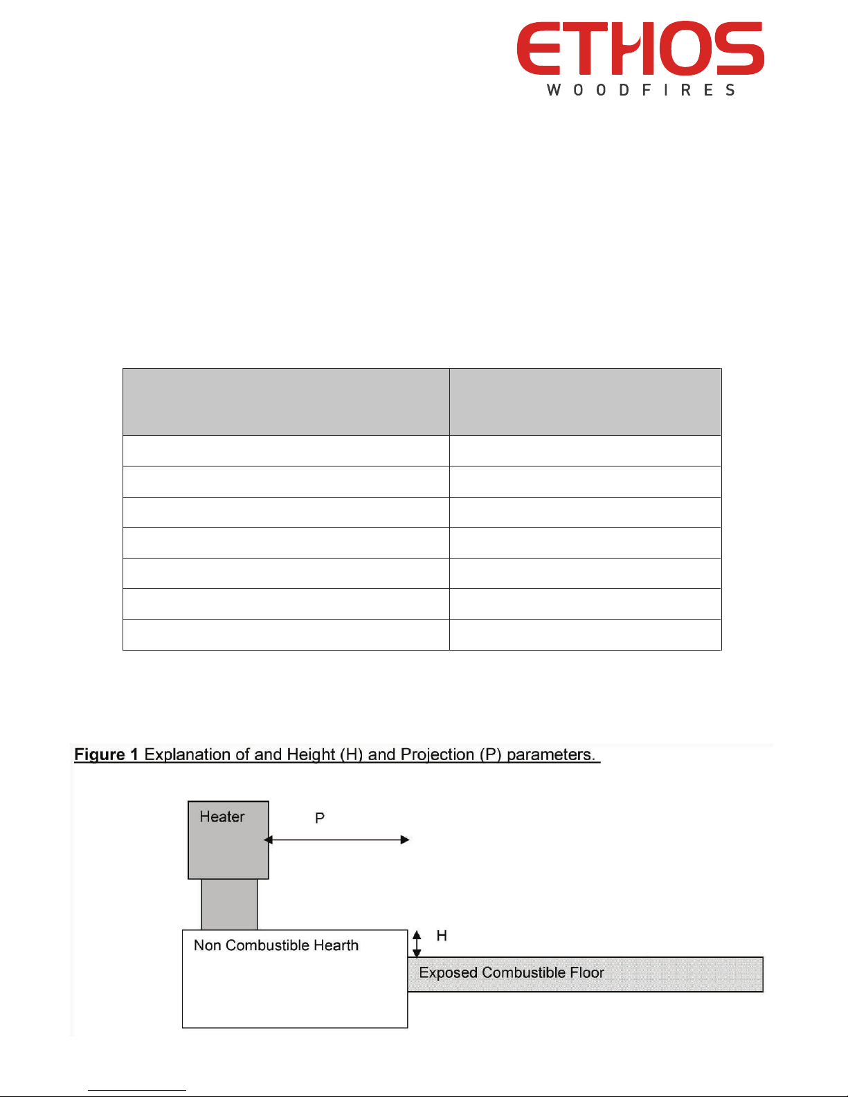
Floor protector: The floor protector must be a minimum of 12mm thick approved heat resistant material.
WARNING: THE APPLIANCE AND FLUE SYSTEM SHALL BE INSTALLED IN ACCORDANCE WITH AS/NZS 2918: 2001
AND THE APPROPRIATE REQUIREMENTS OF THE RELEVANT BUILDING CODE OR CODES.
WARNING: APPLIANCES INSTALLED IN ACCORDANCE WITH THIS STANDARD SHALL COMPLY WITH THE
REQUIREMENTS OF AS/NZS 4013 WHERE REQUIRED BY THE REGULATORY AUTHORITY, I.E. THE APPLIANCE
SHALL BE IDENTIFIABLE BY A COMPLIANCE PLATE WITH THE MARKING “ TESTED TO AS/NZS 4013 ”
ANY MODIFICATION OF THE APPLIANCE THAT HAS NOT BEEN APPROVED IN WRITING FROM THE TESTING
AUTHORITY IS CONSIDERED TO BE IN BREACH OF THE APPROVAL GRANTED FOR COMPLIANCE WITH AS/NZS
4013.
CAUTION: MIXING OF APPLIANCE OR FLUE SYSTEM COMPONENTS FROM DIFFERENT SOURCES OR MODIFYING
THE DIMENTIONAL SPECIFICATION OF COMPONENTS MAY RESULT IN HAZARDOUS CONDITIONS. WHERE SUCH
ACTION IS CONSIDERED, THE MANUFACTURER SHOULD BE CONSULTED IN THE FIRST INSTANCE.
CAUTION: CRACKED AND BROKEN COMPONENTS, e.g. GLASS PANELS OR FIREBRICKS, MAY RENDER THE
INSTALLATION UNSAFE.
THE MANUFACTURER RESERVES THE RIGHT TO CHANGE SPECIFICATIONS OR DESIGNS WITHOUT PRIOR NOTICE
Page 1 of 6
Specications / Installation Instructions
Insert model: Zero Clearance Cabinet for Ares Fire
Eective 1st January 2017
Retain these instructions for future reference
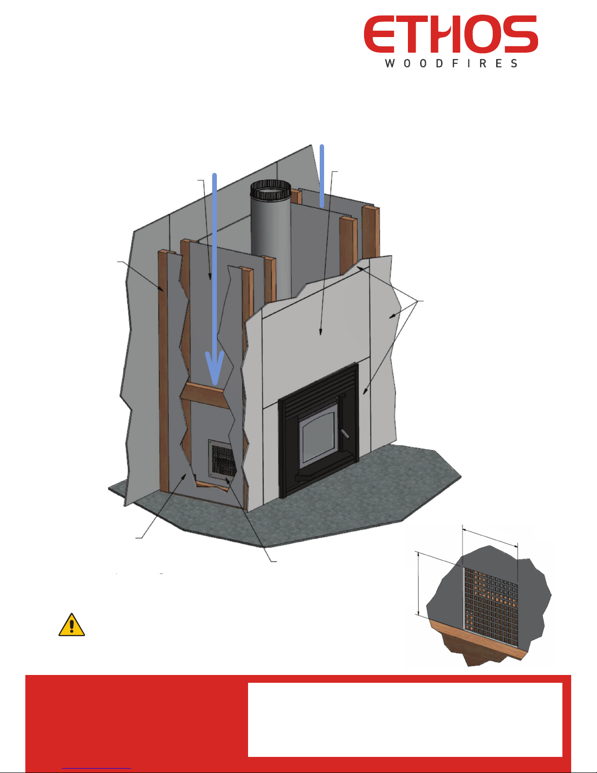
Installation instructions for the Ethos IS100 wood
re with EZC-031135 Zero Clearance Cabinet and
EXA-10042 EconAir ue system
These instructions should be read in conjunction with the instruction
and install documents for the IS100 wood re.

Page 2 of 6
Specications / Installation Instructions
Insert model: Zero Clearance Cabinet for Ares Fire
Eective 1st January 2017
Following these instructions allows for the Ethos IS100 Insert wood re to be safely
installed in a timber frame wall, without the need for further heat protection beyond what
is provided as part of the EZC-031135 Zero Clearance Cabinet and the EXA-10042 EconAir
ue system.
Warning: It is critical that these instructions are followed fully
and that no substitute parts are used.
Important Installation Notes
• Combustible materials must be kept to a minimum of 25mm
away from all parts of the Zero Clearance Cabinet and the
250mm diameter outer ue liner.
• Adequate ventilation must be available for cooling the Zero
Clearance Cabinet. Refer installation diagram example for
supplied ventilation plate mounting details on page 6.
• If installing on combustible oor surfaces such as timber,
option base panel part model EZC-031140 is required to be
tted beneath the Zero Clearance Cabinet. Further details are
shown on page 4.
ETPD0122 rev.7
Page 2 of 6
Following these instructions allows for the Ethos IS100 wood
fire to be safely installed in a timber frame wall, without the need
for further heat protection past that supplied as part of the Zero
Clearance Cabinet and the Econ-Air flue system (see notes
regarding installation on combustible surfaces).
WARNING: It is critical that these instructions are followed
fully and that no substitute parts are used.
INSTALLATION NOTES
1. Combustible materials must be kept a minimum of 25mm away
from all parts of the Zero Clearance Cabinet and the diameter
250 liner.
2. Adequate ventilation must be available for cooling the Zero
Clearance Cabinet - see installation diagram for supplied
ventilation plate mounting detail (page# 6).
3. Ethos insulation base panel (part# ZC1140) is required below
the Zero Clearance Cabinet when in direct contact with
combustible materials such as timber flooring (refer to page# 3
for further detail).
Econ-Air ue system parts list:
3 130mm x 1200mm S/S ue 1 130mm x 600mm S/S ue
2 200mm x 1200mm galv. liner 1 200mm x 600mm galv. liner
1 200mm x 1200mm galv. liner with ‘Z’ brackets 1 250mm x 600mm galv. liner
3 250mm x 1200mm galv. liner 1 130mm spider bracket
4 40mm x 40mm x 600mm mounting rails 1 Ethos revolving cowl (EXS-12010)
1 Ethos IS cowl base (EXS-12002)
These instructions should be read in conjunction with the
instruction documents supplied with your Ethos IS100
wood fire

Page 3 of 6
Specications / Installation Instructions
Insert model: Zero Clearance Cabinet for Ares Fire
Eective 1st January 2017
Floor Insulation Detail
The following table sets out the calculated oor protector projections required to ensure
that temperatures on the exposed oor comply with the requirements of standard
AS/NZS 2918:2001 for exposed oors constructed of medium heat resistant materials.
H = Height of top of Hearth
above Exposed Floor (mm) P = Projection (mm)
0 560
35 488
50 432
75 385
100 343
125 310
135 300

Page 4 of 6
Specications / Installation Instructions
Insert model: Zero Clearance Cabinet for Ares Fire
Eective 1st January 2017
The EXA-10042 EconAir ue system recovers the vented heat
from the Zero Clearance Cabinet and recycles it back into the re
as combustion air for added eciency.
1200 x 600 Supalux
9mm heat resistant board
25mm min clearance
25mm min clearance Side vent panel, one mounted
to each side of the cavity.
Refer to page 6 for further
information.
No insulation required if mounted
on concrete oor.
If mounted on combustible
materials, Ethos part EZC-031140
insulation base panel is required.
25mm min clearance
Liner location brackets
25mm min clearance
EXS-12010 Ethos
revolving cowl
EXS-12002 Ethos IS
cowl base
Roof ashing
130mm Ø stainless
steel exhaust flue
200mm Ø galvanised
inlet flue liner 250mm Ø galvanised Zero
Clearance Cabinet cooling
flue liner
Gib board lining of cavity

Page 5 of 6
Specications / Installation Instructions
Insert model: Zero Clearance Cabinet for Ares Fire
Eective 1st January 2017
Top View Example
1200(w) x 600(h) Supalux
9mm heat resistant board
585mm min depth
25mm min clearance
25mm min
clearance
25mm min clearance
858 mm min width
Open air cavity running down from ceiling
space, allows cooling air to be drawn from
ceiling space to cool Zero Clearance Cabinet.
Heat from Zero Clearance Cabinet is
convected up outer 250mm ue liner.

All information in this instruction document is accurate at the time of printing.
The manufacturer reserves the right to change or amend specifications or designs without notice.
ethosfires.co.nz
ethosfires.com.au
Notes/Installer/Dealer Details
New Zealand
Capisco Ltd
PO Box 938, Whangaparaoa
Auckland 0930
Phone (09) 947 5166
www.capisco.co.nz
Australia
Capisco Aust Pty Ltd
2/281 Pacific Highway
North Sydney, NSW 2060
Phone (02) 8310 7304
www.capisco.com.au
Page 6 of 6
Specications / Installation Instructions
Insert model: Zero Clearance Cabinet for Ares Fire
Eective 1st January 2017
Front 3/4 View Example with Air Cavity and Vent Plates
Vent plate
Timber frame
Gib board wall lining
Cavity to allow cool air
to be drawn from roof
space to ventilate the
Zero Clearance Cabinet
1200mm wide x 600mm high
Supalux 9mm heat resistant
board
Gib board
195mm
180mm
Vent plate
Timber frame
Gib board wall lining
Cavity to allow cool air
to be drawn from roof
space to ventilate the
Zero Clearance Cabinet
1200mm wide x 600mm high
Supalux 9mm heat resistant
board
Gib board
195mm
180mm
It is essential to provide adequate ventilation to the
cavity. Mount supplied ventilation plates centrally and as
low as the timber frame will allow. Ensure the cavity has
access to uninterrupted air supply from ceiling space.
Table of contents
Popular Indoor Fireplace manuals by other brands

Canvas
Canvas 085-1271-6 RICHMOND Assembly instructions

SEI
SEI FA584700TX Assembly instruction

MPC
MPC CORNICE-CAMINO-LIPARI instruction manual

Quadra-Fire
Quadra-Fire COLBAY-INS owner's manual

Majestic
Majestic VERMONT Castings RFSDV34 Installation instructions & homeowner's manual

Seasonal Living
Seasonal Living SUPER BIO FUEL BURNER Safety & user operation manual

Ekofires
Ekofires eko 5070 instruction manual

ARTE
ARTE NEAT 70 Installation & user manual

FMI
FMI C42MW-LS OWNER'S OPERATION AND INSTALLATION MANUAL

Amantii
Amantii TRD-26 Assembly, installation and operation instructions

Desa
Desa CDCFPR OWNER'S OPERATION AND INSTALLATION MANUAL

Amantii
Amantii DE-190040-1 Installation & owner's manual