ETI ADH NETCOM AC NEMA User manual

South Bend, Indiana USA | networketi.com ADH INSTRUCTION MANUAL | PART NO.24100 REV B
1
NETCOM
®MODEL ADH
AUTOMATIC AIR DEHYDRATOR WITH ETHERNET
ADH® NETCOM™ AC NEMA AUTOMATIC AIR
DEHYDRATOR POWER FILTER MODULE
REPLACEMENT PROCEDURE
Replacement Kit Part Number 24087
Document Part Number 24100
SAFETY INFORMATION AND WARNINGS
Abnormal Odor or Smoke
In the event of smoke or a burning or
abnormal odor, immediately interrupt
power to the ADH NETCOM with the
POWER switch at the rear of the unit,
unplug the unit, or turn off the circuit
breaker controlling the outlet. Note
that only the AC model of the ADH
NETCOM has an ON / OFF switch.
Lethal Voltages Present
Lethal voltages are present inside the
ADH NETCOM. Service should be
performed by qualified personnel
only. There are no user serviceable
components inside the chassis.
Pneumatics
Each of the air pumps inside the ADH
NETCOM automatic air dehydrator is
capable of generating as much as 24
psig (1,655mbar). Other attached dry
air sources may be capable of
generating even higher pressures.
Proper safety practice requires
treating all pneumatic components
with care. Always vent the system to
atmospheric pressure before servicing
pneumatic components.
Rack Mounting
Before and after rack mounting the
ADH NETCOM, ensure that the rack
is stable. Mounting of the ADH
NETCOM into a rack should be such
that a hazardous condition is not
created due to uneven mechanical
loading. Verify that adequate air
flow and power source capacity is
available to the unit. Ensure that the
ADH NETCOM maximum operating
temperature of 130°F (55°C) will not
be compromised by other
components in the rack. Ensure
reliable earthing of the ADH
NETCOM.
South Bend, Indiana USA | networketi.com ADH INSTRUCTION MANUAL | PART NO.24100 REV B
2

South Bend, Indiana USA | networketi.com ADH INSTRUCTION MANUAL | PART NO.24100 REV B
3
ADH NETCOM AC NEMA POWER
FILTER MODULE REPLACEMENT
PROCEDURE
This procedure addresses the removal and
replacement of the Power Filter Module in
an ADH NETCOM AC NEMA Automatic Air
Dehydrator. It is recommended to read
the entire procedure prior to beginning
work.
INVENTORY LIST
Identify the following items in this kit prior
to beginning work.
TOOLS REQUIRED
The following tools are needed to perform
this procedure:
•Small flat blade screwdriver
•Nut driver
•Tubing wrench or vacuum tube pliers
•11/32” open end wrench
•Philips screwdriver
•Needle nose pliers
•Long screwdriver
Item
Number
Part
Number
Item
Quantity
Item
Description
1 23563 1 Power Filter Module
22 24100 1 Instruction Manual (this document)

South Bend, Indiana USA | networketi.com ADH INSTRUCTION MANUAL | PART NO.24100 REV B
4
POWER FILTER MODULE
REMOVAL AND REPLACEMENT
To replace the Power Filter Module (23563)
in an ADH NETCOM AC NEMA Automatic
Air Dehydrator, perform the steps below.
1. Shut off machine power by
unplugging the unit.
2. Open the two front door latches,
loosen the two captive screws in the
corners of the housing opposite the
hinges, then open the NEMA box.
Place an object underneath the door
once open to help support it during
this procedure.
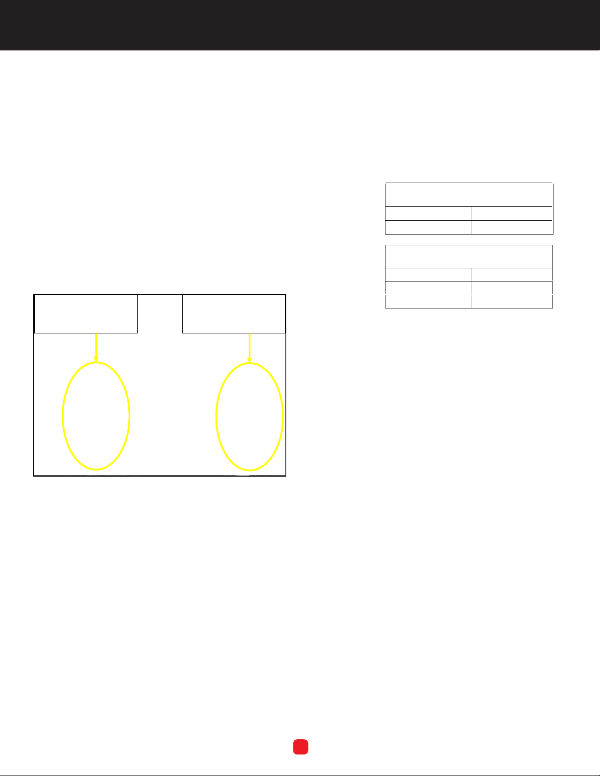
3. Remove the orange Ethernet cable on
the left by disconnecting both ends,
then removing it. Set aside for re-use.
Remove the power cable connector
on the right by loosening the captive
screw on each end of the green
connector, then unplugging the
connector. Disconnect the ground
wire by loosening the ground wire
retaining screw, then carefully
removing the ground wire. Refer to
Figure 1.
Figure 1. DISCONNECTING THE ETHERNET
CABLE,
THE POWER CABLE CONNECTOR, AND
THE GROUND WIRE.
Disconnect
both ends,
then remove
orange
ethernet cable.
Loosen both captive screws,
then disconnect connector.
Loosen
screw,
then
remove
ground
wire.
4. Remove and retain the four mounting
screws from the four corners of the
protective front cover, then slowly lift
the front cover, carefully flip it over,
then set it down, upside down, to rest
on the inside of the enclosure door.
Be careful as there are still many wires
connected between the enclosure
and the front cover and there isn’t a
lot of slack. Note that the two upper
front cover mounting screws are
located in plain sight in the top
corners of the front cover, while the
two lower front cover corner
mounting screws are located down in
the front “well” of the unit. Use a
long-handled screwdriver to remove
them.
South Bend, Indiana USA | networketi.com ADH INSTRUCTION MANUAL | PART NO.24100 REV B
5
5. Note how the five electrical leads are
connected to the existing Power Filter
Module, then use a needle nose pliers
to carefully disconnect the leads from
the module. The two leads on the
Load side connect to the green power
connector. The three leads on the
Line side connect to the power supply.
Of the two connector leads, the black
lead is the line and the white lead is
neutral. Of the three output leads, the
black lead is the line, the white lead is
neutral, and the green/yellow lead is
ground. All of these leads will connect
to the new module the same way.
Figure 2. THE POWER FILTER MODULE.
The two leads on the
Load side connect to
the green power
connector.
The three leads on the
Line side connect to
the power supply.
6. Using the nut driver, remove and
retain the nuts and lock washers
securing the existing module to the
chassis. Once all five electrical leads
have been disconnected and the
mounting hardware has been
removed, remove the existing Power
Filter Module from the unit.
7. Position the new Power Filter Module
over the Pem
®
studs on which the
original module was installed. Using
the nuts and lock washers retained in
step 6, install the new Power Filter
Module and torque to 10 in/lb.
Connect the electrical leads in the
corresponding locations on the new
Power Filter Module from which they
were removed on the old module.
Refer to the following tables. Make
sure all leads are secure.
8.
Load Side Connections
Black Line
NeWhite
Line Side Connections
Black Line
White Ne
Green/Yellow
12. Reinstall the front cover removed in
step 4. If it was placed upside down
on the lid of the unit during this
procedure, carefully turn the cover
back over and work it back into
position, past the wires and other
components in the enclosure.
Reinstall the four corner screws
securing the front cover to the
chassis.
13. Reconnect the ground wire by
inserting it behind the retaining
screw from which it was removed,
then tighten the ground wire
retaining screw. Reconnect the green
power connector by holding it in
place then tightening the two captive
screws removed in step 3. Reconnect
both ends of the orange ethernet
cable removed in step 3. It does not
matter which end of the ethernet
cable goes into which receptacle.

South Bend, Indiana USA | networketi.com ADH INSTRUCTION MANUAL | PART NO.24100 REV B
6
With the ground wire, power
connector and Ethernet cable
reconnected, close the lid of
the NEMA enclosure and
secure the two latches opposite
the hinges. Secure the lid in
place by reinstalling the two
captive screws in the two outer
corners of the lid.
Restore machine power by
plugging the unit back in.
14.
15.
QUESTIONS AND COMMENTS
For technical help, questions, or
comments concerning this or any
ETI, Inc., product, contact the
Customer Service Department
between 8:00 a.m. and 5:00 p.m. EST.
DISCLAIMER
ETI, Inc. makes no representations or
warranties, either expressed or implied
with respect to the contents of this
publication or the products that it
describes, and specifically disclaims any
implied warranties of merchantability or
fitness for any particular purpose. ETI,
Inc. reserves the right to revise this
publication and to make changes and
improvements to the products
described in this publication without the
obligation of ETI, Inc. to notify any
person or organization of such
revisions, changes or improvements.
No part of this manual may be
reproduced or translated in any form or
by any means, electronic or mechanical
including photocopying and recording,
for any purpose without the express
written consent of ETI, Inc.
The ETI logo, We Manage Heat, and
ADH are registered trademarks of ETI,
Inc. NETCOM is a trademark of ETI, Inc.
Copyright © 2012 ETI, Inc. All rights
reserved.
This manual suits for next models
1
Table of contents
Other ETI Dryer manuals


