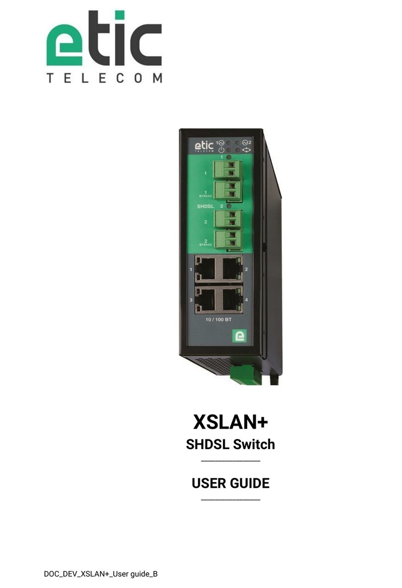
ETIC XSLAN-1100 User manual

DOC_DEV_XSLAN-1100_User guide_A
XSLAN-1100
Switch SHDSL
_________________
USER GUIDE
_________________

DOC_DEV_XSLAN-1100_User guide_A Page 3
DECLARATION OF CONFORMITY
The manufacturer, ETIC Telecom –13 chemin du vieux chêne –38240 Meylan –France, Hereby declares
under sole responsibility that the listed devices conform to
-the Electromagnetic Compatibility (EMC) Directive 2014/30/UE,
-the Low Voltage Directive (LVD) 2014/35/UE,
-the Restriction of the use of certain Hazardous Substances (RoHS 2) Directive 2011/65/UE.
Type of device: SHDSL switch
Models: XSLAN-1100
The harmonized standards to which these devices comply are:
Standard
Title
EN 61000-6-2 2006
Immunity:
EN61000-4-2 Electrostatic Discharge
EN61000-4-3 RF Radiated Immunity
EN61000-4-4 EFT/Burst Immunity
EN61000-4-5 Surge Immunity
EN61000-4-6 RF Conducted Immunity
EN61000-4-8 Power Frequency Magnetic Field Immunity
EN 61000-6-4 2007
A1/2011
Emission:
EN55022 Radiated and conducted emission
IEC/EN 62368
Safety and Health
Date : 06th March 2019
Philippe Duchesne
Technical Director


TABLE OF CONTENTS
DOC_DEV_XSLAN-1100_User guide_A Page 5
OVERVIEW.....................................................................................................................................7
1Purpose of this manual .................................................................................................................................... 7
2Specifications.................................................................................................................................................... 7
3EMC & Environment compliances.................................................................................................................... 9
4Product overview ............................................................................................................................................11
INSTALLATION ...........................................................................................................................13
1Description ...................................................................................................................................................... 13
1.1 Dimensions .......................................................................................................................................... 13
1.2 Connectors........................................................................................................................................... 13
1.3 Push-buttons........................................................................................................................................ 15
1.4 LED indicators......................................................................................................................................16
2Safety instructions.......................................................................................................................................... 16
3DIN rail mounting ............................................................................................................................................ 17
4cooling ............................................................................................................................................................. 17
5Alimentation .................................................................................................................................................... 17
6Earthing ........................................................................................................................................................... 17
7Preparing and checking the line..................................................................................................................... 18
7.1 Type of cable .......................................................................................................................................18
7.2 Crosstalk interference......................................................................................................................... 18
7.3 Shield earthing ..................................................................................................................................... 18
7.4 Protecting the SHDSL switch from lightning ..................................................................................... 19
8Connecting the XSLAN to the line.................................................................................................................. 19
COMMISSIONING .......................................................................................................................21
PREPARING THE ADVANCED SETUP.......................................................................................23
1Connecting a PC for configuration ................................................................................................................ 23
1.1 Overview............................................................................................................................................... 23
1.2 First configuration ............................................................................................................................... 24
1.3 Changing the configuration later ........................................................................................................ 24
2Temporary return to the factory settings ...................................................................................................... 25
3Restoring the factory settings........................................................................................................................ 25
4Protecting the access to the administration server...................................................................................... 26
5Configuration steps ........................................................................................................................................ 26
ANNEX 1 : SHDSL data rate versus distance...........................................................................27


OVERVIEW
DOC_DEV_XSLAN-1100_User guide_A Page 7
OVERVIEW
1Purpose of this manual
The present user guide describes the features and the installation of the SHDSL switch XSLAN-1100.
In the rest of the document the term "XSLAN" is also used to designate the product.
2Specifications
General characteristics
Dimensions
120 x 37 x 88 mm (h,l,p)
Weight
0.44 kg
Casing
Metallic
IP41 –IEC60529
DIN rail mounting
Temperature
Non-operating: -40°/ +85°C
Operating: -20°/ +70°C
Humidity
5 à 95 % relative (non-condensing)
Power supply
Protected against reverse polarity
Nominal : 12-24 VDC (min 10 VDC - max 30 VDC)
2 points Phoenix connector
Consumption
1.8 W
MTBF
730 000 h at 22 °C - MIL-HDBK-217F-N2 GB
SHDSL
Modulation
ITU-T G.991.2, 802.3ah : 2BaseTL (EFM)
Data rate
192 kb/s to 15,2 Mb/s
Emission power
Annex A : 13.5 dBm (22 mW)
Annex B : 14.5 dBm (28 mW)
Voltage of the emitted
signal
6 to 8 V peak to peak on 135 Ohms
Signal spectrum
< 3 MHz at 15 Mb/s
Isolation
1500 V
Connection time
45 s typical
Plug & play
STU-C / STU-R auto-negotiation
Automatic adaptation of the data rate
Latency
Frame transmission delay from one Ethernet port of an XSLAN+ to the Ethernet port of
another XSLAN+ through an SHDSL link : 2 ms at 5.6 Mb/s

PRESENTATION
DOC_DEV_XSLAN-1100_User guide_A Page 8
ETHERNET & IP
Ethernet
10/100 Mb/s Half/Full duplex Auto MDI/MDIX
Switch
Store and forward - 1024 MAC addresses
Redondancy
RSTP - IEEE 802.1D / 802.1Q
VLAN
IEEE 802.1Q
IP address
IPV4 and IPV6
IP router
Multicast and broadcast filtering
Static routes
RIP V2 - OSPF
QOS
RFC 2474, 2475, 2597, 2598 « Differentiated services »
Traffic prioritization and bandwidth reservation
Misc.
SNMP
Supported MIBs:
RFC1213-MIB (MIB-2)
HDSL2-SHDSL-LINE-MIB
HOST-RESOURCES-MIB / IF-MIB
IP-MIB
BRIDGE-MIB
RSTP-MIB
SNMP traps
Date and time
NTP client and server
Configuration
Web serveur
Log
Log with timestamp of the last 300 events
Syslog
Management
Save and restore configurations
Reset product to return to factory configuration

OVERVIEW
DOC_DEV_XSLAN-1100_User guide_A Page 9
3EMC & Environment compliances
EMC Immunity, EN61000-6-2
Standard
Criteria
Port
Level pass
EN61000-4-2
ESD
B
Enclosure
+/-4kv contact
+/-8kv air discharge
EN61000-4-3
Radiated
A
Enclosure
10V/M AM @ 1khz 80Mhz to 3Ghz
EN61000-4-4
Burst
B
SHDSL
+/- 2kv
Power supply
+/- 2kv
Ethernet
+/- 2kv
EN61000-4-5
Surge
B
SHDSL
+/- 5kv common mode (Normal and Telecom
surge)
B
Power supply
+/- 0,5kV common mode
+/- 0,5kV differential mode
Ethernet
+/- 4kv direct shield coupling
EN61000-4-6
RF conducted
A
SHDSL
10VAM 80% 1khz, 150khz to 80Mhz
Power supply
Ethernet
EN61000-4-8
Magnetic
A
Enclosure
30 A/M at 50hz/60hz
EN61000-4-18
Damped wave
A
Power supply
+/- 0,5kV differential
B
+/- 1kV common mode
A
Ethernet
+/- 1kV common mode
B
SHDSL
+/- 1kV common mode
EMC Immunity, ITU -T-K21
Test
Criteria
Port
K44 Test N°
Lightning voltage,
special test protector
A
SHDSL
2.1.2a
+/- 5kV transverse mode (Basic level)
2.1.2b
+/- 5kV port to earth (Basic level)
EMC Emissions, EN61000-6-4
Emission test
Criteria
Limits
conducted Disturbance
Power supply
EN55032, Class A: 150khz to 30Mhz
SHDSL
Ethernet
Radiated emission
Enclosure
EN55032, Class A: 30Mhz to 1Ghz

PRESENTATION
DOC_DEV_XSLAN-1100_User guide_A Page 10
Climatic
Standard
Test
Level
EN 60068-2-1
Cold
Ab
-40 °C - 16 hours –Non-operating
Ad
-40 °C - 16 hours –Operating
EN 60068-2-2
Dry heat
Bb
+85 °C - 16 hours –Non-operating
Bd
+70 °C - 16 hours –Operating
EN 60068-2-14
Change of temperature
Na
-25 °C à +70 °C –Non-operating
5 cycles of 2 hours
Nb
-40 °C à +70 °C –Operating
3 °K/mn - 5 cycles de 2 hours
EN 60068-2-30
Damp heat
Db
Variante 2
+25 °C à 55 °C –Operating
2 cycles

OVERVIEW
DOC_DEV_XSLAN-1100_User guide_A Page 11
4Product overview
The XSLAN-1100 is an industrial Ethernet switch that provides 1 SHDSL port to extend Ethernet transmission
over several kilometers using any existing copper pair.
The data rate is up to 5,7 Mb/s on 3,7 Km and 15 Mb/s on 0,7 Km (see table in Annex 1).
The XSLAN-1100 is a « Plug & Play » product. It does not require any configuration. Just make the different
connections. The SHDSL link is established in a few tens of seconds. Equipment located on either side of the
line can communicate with each other as if they were connected locally.
The XSLAN-1100 is designed to operate in harsh environments, climatic and electromagnetic. In particular,
it is equipped with lightning protection.
The XSLAN-1100 is eco-friendly. Despite its powerful advanced features, it consumes little energy. The level
of the electromagnetic emission is very low.
The XSLAN-1100 can interwork with any switch in the XSLAN family. For example, it is possible to connect
an XSLAN-1100 at one end of the line and an XSLAN+2220 at the other end.
The XSLAN-1100 also offers advanced features. These functions are configured using a Web browser:
•IP routing and filtering
The XSLAN can remove the broadcast frames on the SHDSL link by routing the IP frames, and thus
limiting the unwanted traffic on the SHDSL link.
•VLAN
The XSLAN+ features VLAN:
It is useful, for example, to separate the flows on the SHDSL link from those for the administration of
the switch.
•Quality of service DiffServ
The XSLAN can manage different IP traffics with different priorities.
•SNMP
The XSLAN can be monitored by an SNMP manager and supports the main MIB of an Ethernet switch
and the SHDSL MIB.
1 twisted pair


INSTALLATION
DOC_DEV_XSLAN-1100_User guide_A Page 13
INSTALLATION
1Description
1.1 Dimensions
All dimensions in millimeters.
1.2 Connectors
Shield terminal
SHDSL screw block
Ethernet
Power supply
screw block
Ground terminal

INSTALLATION
DOC_DEV_XSLAN-1100_User guide_A Page 14
Ground terminal
Symbol
Description
M4 screw terminal
Shield terminal
Symbol
Description
M4 screw terminal –Shield connection of the transmission cable
2 positions screw terminal: Supply voltage
Protected against reverse polarity
Position
Signal
Function
1
Power 1 +
12 - 24 VDC
2
Power 1 -
0V
2 positions screw terminal: SHDSL
Position
Signal
Function
1
Line
SHDSL line conductor
2
Line
SHDSL line conductor
Ethernet RJ45 connector
Position
Signal
Function
RJ45
1
Tx +
Emission polarity +
2
Tx -
Emission polarity -
3
Rx +
Reception polarity +
4
N.C
-
5
N.C
-
6
Rx -
Reception polarity -
7
N.C.
-
8
N.C.
-

INSTALLATION
DOC_DEV_XSLAN-1100_User guide_A Page 15
1.3 Push-buttons
Front panel push-button: B1
Pressing the PB
LED AUTO
Function
3 seconds
Steady green
Automatic connection mode
No IP address and no access to the Web pages
Rear panel push-button: B2
Pressing the PB
LED
Function
During operation
Flashing red
Temporary return to the factory configuration.
(IP address 192.168.0.128)
The current configuration is not lost.
During power-up
Flashing red
Return to the factory configuration.
The current configuration is deleted except if it has been
saved into a file.
B1
B2

INSTALLATION
DOC_DEV_XSLAN-1100_User guide_A Page 16
1.4 LED indicators
LED indicators
Function
LED
Description
Opération
Off Power off
Steady green The unit is ready
Slow blinking green The unit is busy
Steady red Startup (30s) –Otherwise hardware or software failure
Fast blinking red Firmware download in progress
SHDSL
Connection
SHDSL
Off Port disable
Blinking Connection in progress
On Connection established
Flashing Traffic on the link
SHDSL
Data rate
Off No connection
1 flash 64 kb/s ≤ Data rate < 512 kb/s
2 flashes 512 kb/s ≤ Data rate < 2048 kb/s
3 flashes 2048 kb/s ≤ Data rate
Mode
AUTO
Off Advanced configuration and diag. mode (Web pages)
On Auto mode (no web page)
2Safety instructions
The product shall be installed in a fire electrical resistant cabinet by a qualified operator.
The product must be connected only to equipment that complies with the IEC60950-1 or IEC62368-1 standards
and that meets the following classifications:
•IEC60950-1 : Limited power circuits and SELV type –§2.2 and 2.5
•IEC62368-1 : ES1 & PS2
To avoid any risk of burns, it is strongly recommended to wear gloves to handle the product in
operation when the ambient temperature exceeds 30 °C.

INSTALLATION
DOC_DEV_XSLAN-1100_User guide_A Page 17
3DIN rail mounting
Mounting the unit on the 35 mm DIN rail
Removing the unit from the DIN rail
4cooling
The product is designed to be mounted on a 35mm DIN rail.
To avoid obstructing the airflow around the unit, the spacing must be at least 25 mm above and below, and 10
mm left and right.
5Alimentation
The supply voltage must be regulated and strictly between 10 and 30 Volt DC (nominal: 12 –24 VDC).
At power up the inrush current can reach 20 A for 100 µs.
In operation, the consumption can reach 2W during short moments (peak).
6Earthing
The enclosure of the XSLAN-1100 is metallic ; For safety and EMC reasons, the ground terminal must be
connected to the protective earth of the installation.
1
2

INSTALLATION
DOC_DEV_XSLAN-1100_User guide_A Page 18
7Preparing and checking the line
7.1 Type of cable
Twisted pair cable
The XSLAN+ SHDSL switch is designed to be connected to one or several telephone grade twisted pairs.
The conductor diameter must be included between 0.4 mm and 1 mm.
A cable may be composed of several twisted pairs.
Each pair can usually be used for a different SHDSL transmission if necessary. However, care must be taken
to ensure that crosstalk between pairs is not excessive.
Cable made of quads
It often happens that the twisted pairs of the same cable are wound in groups of two pairs; a group of two
pairs rolled into each other is called a quad.
This type of cable is suitable. However, we will try to use only one pair per quad to avoid crosstalk (see below).
Shielded cable
It is better to use a shielded cable.
The shield must be connected to the earth at one of its ends.
The shield decreases the influence of the electromagnetic ambient noise on the SHDSL signal.
Moreover, the shield protects the XSLAN against lightning.
Electrical power cable
Two power conductors can be used instead of a twisted pair to set an SHDSL connection.
However, because the two wires are not twisted, the ambient electrical noise may disturb the transmission.
Compared to the transmission over a twisted pair, the maximum distance between two SHDSL switches is
decreased.
7.2 Crosstalk interference
If the cable is made of several pairs, a signal transmitted in one pair may disturb the signal transmitted in
another one, and, in some cases, may decrease the effective data rate of the SHDSL connection.
The closer the pairs, the greater the crosstalk. Thus the risk of crosstalk is higher between two pairs of the
same quad.
This is why, if the cable is made up of quads, it is advisable to avoid using the two pairs of the same quad.
7.3 Shield earthing
A shielded cable provides better noise immunity and surges protection during thunderstorms.
The best protection is provided when the shield is earthed at each end of the line.
However, there may be a large potential difference between the connection points to the earth, especially when
the line is long.
Therefore, to avoid a large current flowing in the shield, it is recommended to connect the shield to the earth
at only one end of the cable.

INSTALLATION
DOC_DEV_XSLAN-1100_User guide_A Page 19
7.4 Protecting the SHDSL switch from lightning
The XSLAN is coupled to the line by a transformer which provides isolation between the circuit board and the
line. Moreover, the XSLAN+ is equipped with internal protections against overvoltage.
However, if the line is vulnerable to thunderstorms, for example if it is an air line, or if it is several kilometers
long, or if the installation is in a very exposed area, it is recommended to protect each XSLAN with a surge
protector, as described below.
8Connecting the XSLAN to the line
The SHDSL signal is not polarized; the two wires of the twisted pair can be interchanged.
Check that the shield, if any, is properly earthed.
When the XSLAN is directly connected to the line without the use of an external surge protector, the shield of
the cable will be connected to the shield terminal which provides electrical continuity with the ground terminal.
1 twisted pair
Surge arrestor
Cable shield
connected to earth
à la terre

Table of contents
Other ETIC Switch manuals

