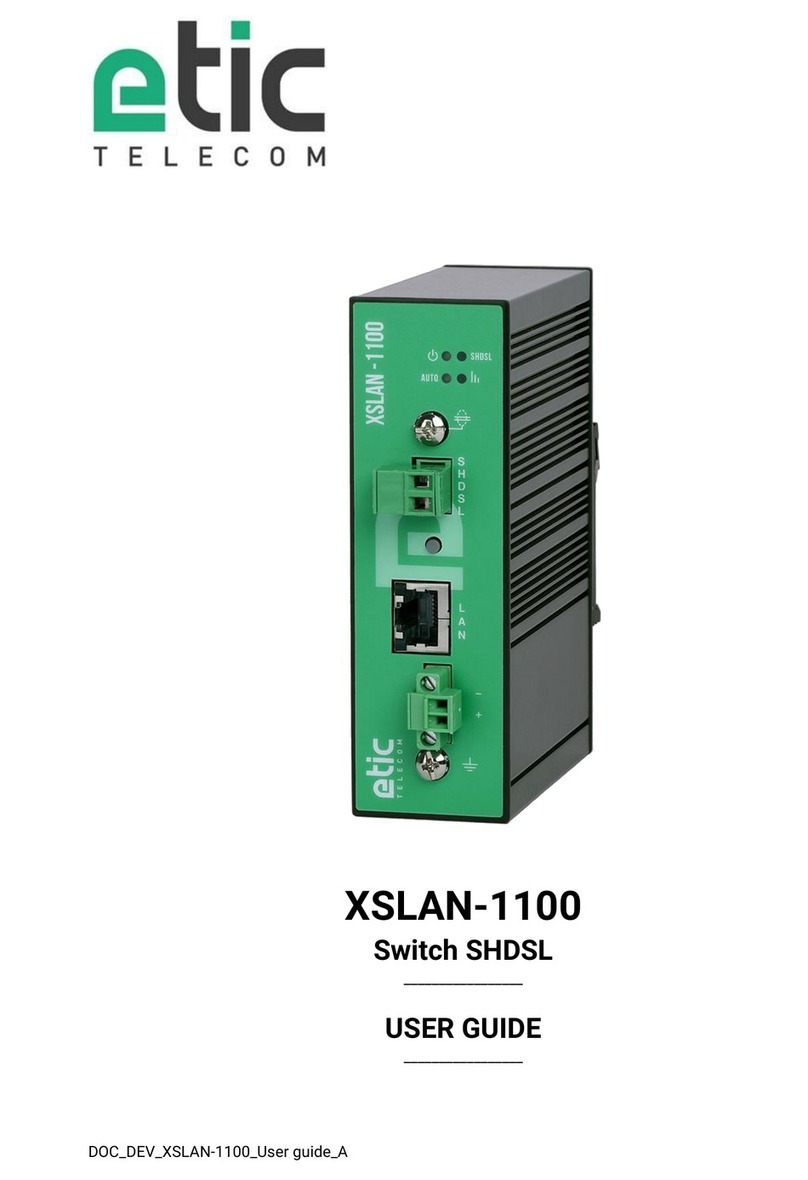
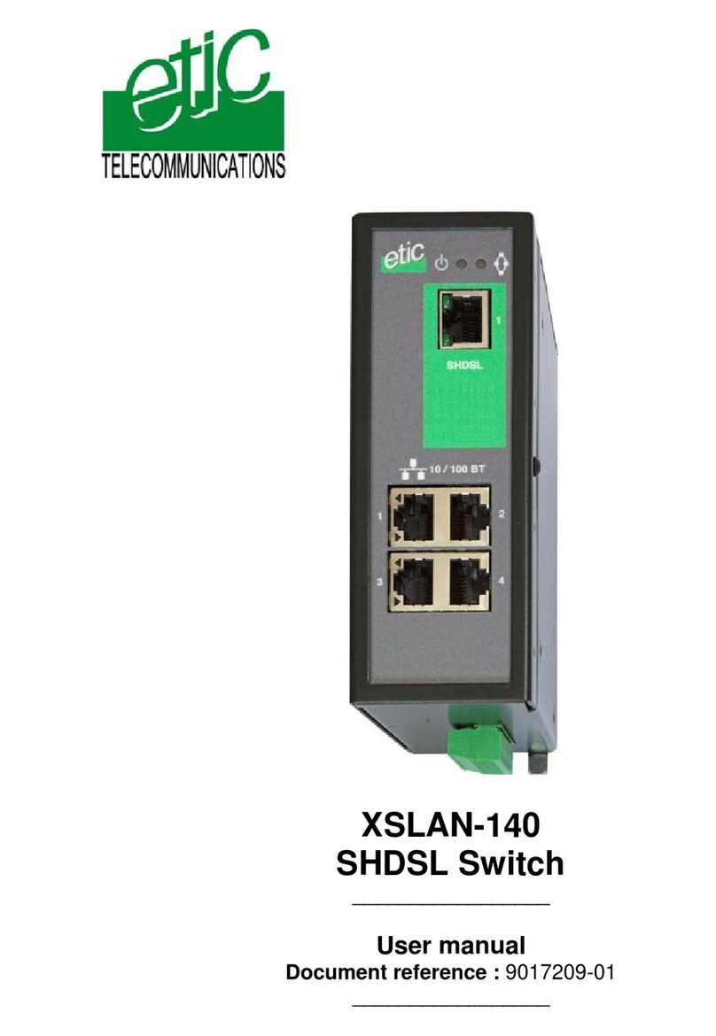
ETIC XSLAN+ Series User manual

DOC_DEV_XSLAN+_User guide_B
XSLAN+
SHDSL Switch
_________________
USER GUIDE
_________________

DOC_DEV_XSLAN+_User guide_B Page 3
DECLARATION OF CONFORMITY
The manufacturer, ETIC Telecom –13 chemin du vieux chêne –38240 Meylan –France, Hereby declares
under sole responsibility that the listed products conform to
-the Electromagnetic Compatibility (EMC) Directive 2014/30/UE ,
-the Low Voltage Directive (LVD) 2014/35/UE ,
-the Restriction of the use of certain Hazardous Substances (RoHS) Directive 2011/65/UE.
Type of product: SHDSL switch
Models:
XSLAN+140
XSLAN+1400, XSLAN+1220, XSLAN+1230, XSLAN+1260, XSLAN+1261
XSLAN+2400, XSLAN+2220, XSLAN+2230, XSLAN+2260, XSLAN+2261
XSLAN+BP2400, XSLAN+BP2220, XSLAN+BP2230, XSLAN+BP2260, XSLAN+BP2261
XSLAN+4400, XSLAN+4220, XSLAN+4230, XSLAN+4260, XSLAN+4261
The harmonized standards to which these products comply are:
Standard
Title
EN 61000-6-2 2006
Immunity:
EN61000-4-2 Electrostatic Discharge
EN61000-4-3 RF Radiated Immunity
EN61000-4-4 EFT/Burst Immunity
EN61000-4-5 Surge Immunity
EN61000-4-6 RF Conducted Immunity
EN61000-4-8 Power Frequency Magnetic Field Immunity
EN 61000-6-4 2007
A1/2011
Emission:
EN55022 Radiated and conducted emission
EN 60950-1/A2 2014
Safety and Health
Date : 11th October 2017
Philippe Duchesne
Technical Director
NOTE:
This equipment has been tested and found to comply with the limits for a Class A digital device, pursuant to
Part 15 of the FCC Rules. These limits are designed to provide reasonable protection against harmful
interference when the equipment is operated in a commercial environment. This equipment generates, uses,
and can radiate radio frequency energy and, if not installed and used in accordance with the instruction
manual, may cause harmful interference to radio communications. Operation of this equipment in a
residential area is likely to cause harmful interference in which case the user will be required to correct the
interference at his own expense.


TABLE OF CONTENTS
DOC_DEV_XSLAN+_User guide_B Page 5
OVERVIEW.....................................................................................................................................7
1Purpose of this manual .................................................................................................................................... 7
2Products identification ..................................................................................................................................... 7
3Specifications.................................................................................................................................................... 8
4Product overview ............................................................................................................................................10
4.1 XSLAN+1XXX....................................................................................................................................... 10
4.2 XSLAN+2XXX....................................................................................................................................... 10
4.3 XSLAN+4200........................................................................................................................................ 12
5Highlighted features ....................................................................................................................................... 14
5.1 STU-C / STU-R auto-negotiation ......................................................................................................... 14
5.2 Redundancy solutions: RSTP and proprietary failsafe ring............................................................... 14
5.3 The by-pass function........................................................................................................................... 15
5.4 The loop VPN function ........................................................................................................................ 15
5.5Other functions of the XSLAN+ family ............................................................................................... 16
INSTALLATION ...........................................................................................................................17
1Description ...................................................................................................................................................... 17
1.1 Dimensions .......................................................................................................................................... 17
1.2 Connectors........................................................................................................................................... 17
1.3 Push button.......................................................................................................................................... 22
1.4 LED indicators......................................................................................................................................23
2Safety instructions.......................................................................................................................................... 24
3DIN rail mounting ............................................................................................................................................ 25
4Cooling............................................................................................................................................................. 25
5Power supply................................................................................................................................................... 25
6Isolation and earthing..................................................................................................................................... 26
7RS232 serial connection (XSLAN+X220 or XSLAN+X230) .......................................................................... 26
8RS485 serial connection (XSLAN+X220) ...................................................................................................... 26
9RS422 isolated serial connection (XSLAN+X260) ........................................................................................ 27
10 RS485 isolated serial connection (XSLAN+X261) .................................................................................... 28
11 Digital input and output............................................................................................................................... 29
12 Preparing and checking the line ................................................................................................................. 29
12.1 Type of cable....................................................................................................................................29
12.2 Crosstalk interference ..................................................................................................................... 30
12.3 Shield earthing ................................................................................................................................. 30
12.4 Protecting the SHDSL switch from lightning.................................................................................. 30
13 Connecting the XSLAN+ to the line............................................................................................................ 30
13.1 General precautions......................................................................................................................... 30
13.2 Point to point connection using two, three or four twisted pairs.................................................. 31
13.3 Daisy chain or ring connection........................................................................................................ 31
13.4 By-pass function .............................................................................................................................. 31
PREPARING THE SETUP............................................................................................................33
1Connecting a PC for configuration ................................................................................................................ 33

TABLE OF CONTENTS
Page 6 DOC_DEV_XSLAN+_User guide_B
1.1 Overview............................................................................................................................................... 33
1.2 First configuration ............................................................................................................................... 34
1.3 Changing the configuration later ........................................................................................................ 34
2Temporary return to the factory settings ...................................................................................................... 35
3Restoring the factory settings........................................................................................................................ 35
4Protecting the access to the administration server...................................................................................... 36
5Configuration steps ........................................................................................................................................ 36
ANNEX 1 : SHDSL data rate versus distance...........................................................................37

OVERVIEW
DOC_DEV_XSLAN+_User guide_B Page 7
OVERVIEW
1Purpose of this manual
The present user guide describes the features and the installation of the XSLAN+ switches family (it also
applies to the switches family previously named XSRING+).
2Products identification
The XSLAN+ is an industrial Ethernet switch that provides 1 to 4 SHDSL ports to extend the Ethernet
transmission up to several kilometers using any existing copper pair.
The XSLAN+ switches family consists of these models :
XSLAN+1400, XSLAN+1220, XSLAN+1230, XSLAN+1260, XSLAN+1261
XSLAN+2400, XSLAN+2220, XSLAN+2230, XSLAN+2260, XSLAN+2261
XSLAN+BP2400, XSLAN+BP2220, XSLAN+BP2230, XSLAN+BP2260, XSLAN+BP2261
XSLAN+4200, XSLAN+BP4200
The main features are summarized hereafter :
XSLAN+ models
1400
12xx
2400
22xx
BP2400
BP22xx
4200
BP4200
SHDSL port
1
1
2
2
2
2
4
4
Max. data rate (Mb/s)
15.2
15.2
30.4
30.4
30.4
30.4
60.8
60.8
Ethernet port 10-100 Mb/s
4
2
4
2
4
2
2
2
RS232/RS485 *
N
Y
N
Y
N
Y
N
N
By-pass
N
N
N
N
Y
Y
N
Y
Failsafe ring
N
N
Y
Y
Y
Y
Y
Y
Serial gateway
raw, telnet, modbus,
unitelway
N
Y
N
Y
N
Y
N
N
*Models with serial interface code :
xx
RS232
RS485
RS422
isolated
RS485
isolated
20
1
1
0
0
30
2
0
0
0
60
0
0
1
0
61
0
0
0
1

OVERVIEW
Page 8 DOC_DEV_XSLAN+_User guide_B
3Specifications
Dimensions
136 x 48 x 138 mm (h, l, p)
Weight
Max 0.74 kg
Casing
Metallic
IP20 –IEC60529
DIN rail mounted
Temperature
Storage: - 40°/ + 85°C
Operating: - 40°/ + 70°C
Humidity
10 to 95 % (relative)
Power supply
2 power supply inputs
Reverse polarity protection
Nominal : 12-48 VDC (min 10 VDC - max 60 VDC)
Consumption
XSLAN+1400 or +12xx : 5W
XSLAN+2400 or +22xx : 6W
XSLAN+4200 : 9W
EMC
Susceptibility EN61000-6-2 :
ESD : EN61000-4-2 : 4 kV contact –8kV air
RF radiated : EN61000-4-3 : 10V/m < 2 GHz
Burst : EN61000-4-4
Surge : EN61000-4-5 : 4KV line / earth
RF conducted : EN61000-4-6
Magnetic fields : EN61000-4-8
Emission conducted and radiated :
EN 55022
Electrical safety
EN 60950-1
Hazardous materials
2011/65/UE (RoHS)
REACH
SHDSL
ITU-T G.991.2, 802.3ah : 2BaseTL (EFM)
Data rate: 192 kb/s to 15,2 Mb/s on 1 pair
Isolation 1500 V
Connection time: 45 s typical
STU-C / STU-R auto-negotiation
Latency
Frame transmission delay from one Ethernet port of an XSLAN+ to the Ethernet port of another
XSLAN+ through an SHDSL link : 4 ms at 5.6 Mb/s
Ethernet
10/100 Mb/s Half/Full duplex Auto MDI/MDIX
Switch
Store and forward - 1024 addresses MAC
Redundancy
RSTP - IEEE 802.1D / 802.1Q
Fail safe ring
Loop VPN
VLAN
IEEE 802.1Q
IP address
IPV4 and IPV6
IP router
Multicast and broadcast filtering
Static routes
RIP V2 - OSPF

OVERVIEW
DOC_DEV_XSLAN+_User guide_B Page 9
QOS
RFC 2474, 2475, 2597, 2598 « Differentiated services »
Traffic prioritization and bandwidth reservation
SNMP
Supported MIBS :
RFC1213-MIB (MIB-2)
HDSL2-SHDSL-LINE-MIB
HOST-RESOURCES-MIB / IF-MIB
IP-MIB
BRIDGE-MIB
RSTP-MIB
RS232-RS485 *
Asynchronous - 1200 à 115200 kb/s with or without parity
Gateway : Raw TCP client and server / UDP multipoint / Multicast / Telnet
Modbus / Unitelway
Date and time
NTP client and server
Log
Log with timestamp of the last 300 events
Syslog
Alarm
1 digital output
SNMP traps
Configuration
With HTML browser
* depending on models

OVERVIEW
Page 10 DOC_DEV_XSLAN+_User guide_B
4Product overview
The XSLAN+ switches family includes :
The products which can be connected to only one twisted pair.
They only provide one SHDSL interface.
The references of that products are XSLAN+1400 or XSLAN+12xx if they provide a serial port.
They are named XSLAN+1XXX hereafter.
The products which can be connected to two twisted pair.
They provide two SHDSL interfaces.
The references of that products are XSLAN+2400 or XSLAN+22xx if they provide a serial port.
They are named XSLAN+2XXX hereafter.
The products which can be connected to four twisted pair.
They provide four SHDSL interfaces.
The references of that products are XSLAN+4200.
4.1 XSLAN+1XXX
Point to point link on a single twisted pair
Two XSLAN+1XXX extend Ethernet over one
twisted pair.
The data rate is up to 5,7 Mb/s on 3,7 Km and 15
Mb/s on 0,7 Km (see table in Annex 1).
4.2 XSLAN+2XXX
Additional features compared to XSLAN+1XXX:
Point to point link on two twisted pairs
Two XSLAN+2XXX extend Ethernet over two
aggregated twisted pair.
The data rate is twice the data rate on a single
pair: up to 11,4 Mb/s on 3,7 Km and 30 Mb/s on
0,7 Km (see table in Annex 1).

OVERVIEW
DOC_DEV_XSLAN+_User guide_B Page 11
In case of a failure of a pair the data
transmission is maintained on the other pair
(backup).
Daisy chain link
The XSLAN+2XXX is used to
interconnect a series of Ethernet
networks using a single twisted pair.
Thanks to the Store and Forward
principle, the number of switches is
not limited.
Point to multipoint link
The XSLAN+2XXX is used to interconnect a central site with two
remote sites.

OVERVIEW
Page 12 DOC_DEV_XSLAN+_User guide_B
RSTP redundant link of fail safe ring
Redundant network ring using the proprietary
protocol (or RSTP)
Complex network topology and "multi-
manufacturer" using the RSTP standard
protocol.
4.3 XSLAN+4200
Additional features compared to XSLAN+2XXX:
Point to point link on four twisted pairs
Two XSLAN+4200 extend Ethernet over two, three or four
aggregated twisted pair.
The data rate is the sum of the data rate on each pair: up to
22,8 Mb/s on 3,7 Km and 60 Mb/s on 0,7 Km (see table in
Annex 1).
In case of a failure of one or more pairs, the data transmission
is maintained on the remaining pairs (backup).

OVERVIEW
DOC_DEV_XSLAN+_User guide_B Page 13
Point to multipoint link - Concentrator
The XSLAN+4200 is used to interconnect a
central site with four remote sites.
Point to multipoint link with doubled data rate
The XSLAN+4200 is used to interconnect a central site with two
remote sites.
Redundant ring with doubled data rate
Redundant ring with 2 pairs
aggregated on each side.

OVERVIEW
Page 14 DOC_DEV_XSLAN+_User guide_B
5Highlighted features
5.1 STU-C / STU-R auto-negotiation
When two XSLAN+ are connected by a twisted pair, one switch initiates the connection while the other
responds and adapts automatically its data rate.
The switch that initiates the connection is called STU-C.
The switch that responds and adapts is called STU-R.
Thus a line is always connected on one side to a switch acting as the STU-C and on the other side to a
switch acting as the STU-R.
One switch is normally configured as a STU-C and the other as a STU-R. However, to make the configuration
simpler, the switch configured as a STU-C is able to automatically change to STU-R mode if it detects the
presence of a STU-C on the remote side. Thus, two XSLAN+ configured both in STU-C will find a way to
connect. One of the two will switch to STU-R.
5.2 Redundancy solutions: RSTP and proprietary failsafe ring
Industrial applications need reliable networks; one way to provide reliability is to provide backup paths which
form loops in the Ethernet network.
However, loops are highly unwelcome in Ethernet networks, as they can cause broadcast storms, eating up all
the available bandwidth and causing network outage.
The goal of redundancy protocols is to make Ethernet work of networks containing loops and to provide a path
at each time, even, if possible, when one or several links are in failure.
The XSLAN+ provides two solution to handle redundancy :
RSTP :
RSTP, standing for "Rapid Spanning Tree Protocol" is specified by the IEEE in the 802.1D-2004 document.
RSTP can handle complex structures ; RSTP can be used with devices from other manufacturers.
The failure detection delay and the recovery delay in an SHDSL network is around 10 seconds.
1 twisted pair
The STU-C switch
negociates the data
rate
The STU-R switch
automatically adapts
STU-C
STU-R

OVERVIEW
DOC_DEV_XSLAN+_User guide_B Page 15
Proprietary failsafe ring algorithm:
Based on the STP algorithm, that solution makes possible to handle a ring structure up to 16 SHSDL switches.
The advantages of that solution is that the failure detection delay and the recovery delay is only a few seconds
(One second if the ring counts 5 SHDSL switches); moreover, it is very simple to configure.
5.3 The by-pass function
When the network is a daisy chain –that case is very frequent in industrial applications - and when, however,
it is not possible to build a failsafe structure like a ring, the XSLAN+BP offers a very useful function called the
“By-pass function”.
The XSLAN+BP includes an electro-mechanical relay between both lines; that relay is automatically closed to
connect the two lines when the XSLAN+BP is switched off.
For instance, if the XSLAN+ #2 cabinet is switched off
for maintenance, the by-pass relay inside the XSLAN+
#2 will automatically connect the line coming from the
XSLAN+ #1 to the line going to the XSLAN+ #3.
After a few seconds, the XSLAN+ #1 detects the
connection default and establishes immediately the
connection with the XSLAN+ #3.
5.4 The loop VPN function
When the SHDSL network forms a daisy chain (ie a linear topology), and when it is not possible to form a
secure ring, the "loop VPN" function allows for network redundancy if a public WAN connection (Internet) or
private (MPLS) is available at each end of the SHDSL network.

OVERVIEW
Page 16 DOC_DEV_XSLAN+_User guide_B
The 2 XSLAN+ at the end of the
network establish a VPN over the
WAN. The VPN provides
connectivity at the Ethernet level.
Thus by activating the RSTP
protocol redundancy may be
provided thanks to that VPN.
5.5 Other functions of the XSLAN+ family
Data rate versus distance
The table in Annex 1 gives the data rate which can be expected over a line versus the length of the line.
Each interface features an adaptive data rate from 192 Kb/s up to 15,2 Mb/s.
When using several aggregated pairs, the total data rate that can be obtained is equal to the sum of the data
rates on each pairs.
Ethernet and serial interface
Depending on the model, the products have either 4 RJ45 Ethernet interfaces, or 2 Ethernet and 1 or 2 serial
interfaces associated with a gateway function that allows the easy integration of equipment with RS232 or
RS485 or RS422 serial interface to the Ethernet network.
IP routing and filtering
The XSLAN+ can remove the broadcast frames on the SHDSL link by routing the IP frames, and thus limiting
the unwanted traffic on the SHDSL link.
VLAN
The XSLAN+ features VLAN :
Each Ethernet port can be assigned to a particular VLAN. A device connected to an Ethernet port belonging to
a particular VLAN can communicate only with devices connected to Ethernet ports belonging to the same one.
Quality of service DiffServ
The XSLAN+ can manage different IP traffics with different priorities.
SNMP
The XSLAN+ can be monitored by an SNMP manager and supports the main MIB of an Ethernet switch and
the SHDSL MIB.
Configuration
The products are configured with an html browser.

INSTALLATION
DOC_DEV_XSLAN+_User guide_B Page 17
INSTALLATION
1Description
1.1 Dimensions
All models XSLAN+1XXX or XSLAN+2XXX or XSLAN+4200
The height indicated ignores the
bulk of the power connector on the
bottom side.
1.2 Connectors
XSLAN+1400
XSLAN+1220

INSTALLATION
Page 18 DOC_DEV_XSLAN+_User guide_B
XSLAN+1230
XSLAN+1260
XSLAN+1261
XSLAN+2400
For XSLAN+22XX :
See XSLAN+12XX

INSTALLATION
DOC_DEV_XSLAN+_User guide_B Page 19
XSLAN+BP2400
For XSLAN+BP22XX :
See XSLAN+12XX
XSLAN+4200
XSLAN+BP4200
The By-passed ports are port 3 and port 4 only.

INSTALLATION
Page 20 DOC_DEV_XSLAN+_User guide_B
Ground terminal
Symbol
Description
FASTON male lug 6.35 mm
2 positions screw terminal: Supply voltage 1
Position 1 at back - Protected against reverse polarity
Position
Signal
Function
1
Power 1 +
+V : 12 –48 V DC
2
Power 1 -
0V isolated from the enclosure
2 positions screw terminal: Supply voltage 2
Position 1 at back - Protected against reverse polarity
Position
Signal
Function
1
Power 1 +
+V : 12 –48 V DC
2
Power 1 -
0V isolated from the enclosure
4 positions screw terminal: Digital input and output
Position 1 at back
Position
Signal
Function
1
3V3
3 V DC provided by the XS+
2
In
Digital input
3
F +
Digital output + (max 48Vdc - 0,5A)
4
F -
Digital output -
XSLAN+1XXX or XSLAN+2XXX or XSLAN+4200
2 positions screw terminal :
SHDSL1 & SHDSL2 & SHDSL3 & SHDSL4
Position
Signal
Function
1
Line
SHDSL line conductor
2
Line
SHDSL line conductor
XSLAN+BP2XXX
2 positions screw terminal :
SHDSL1 & SHDSL2 & SHDSL1 by_pass & SHDSL2 by-pass
Position
Signal
Function
1
Line
SHDSL line conductor if the by-pass function is used
2
Line
SHDSL line conductor if the by-pass function is used
XSLAN+BP4200
2 positions screw terminal :
SHDSL1 & SHDSL2 & SHDSL3 by_pass & SHDSL4 by-pass
Position
Signal
Function
1
Line
SHDSL line conductor if the by-pass function is used
2
Line
SHDSL line conductor if the by-pass function is used
This manual suits for next models
21
Table of contents
Other ETIC Switch manuals
Popular Switch manuals by other brands
Guard master
Guard master Centurion installation instructions

Black Box
Black Box ServSwitch ACU5001A Specifications
Planet
Planet IGS-4215 Series Quick installation guide
3One data
3One data IPS7112G-4GS-8GPOE user manual

AirLive
AirLive POE-GSH504ATi Quick setup guide
ICRealtime
ICRealtime PWR-POE-8-V3 quick start guide

