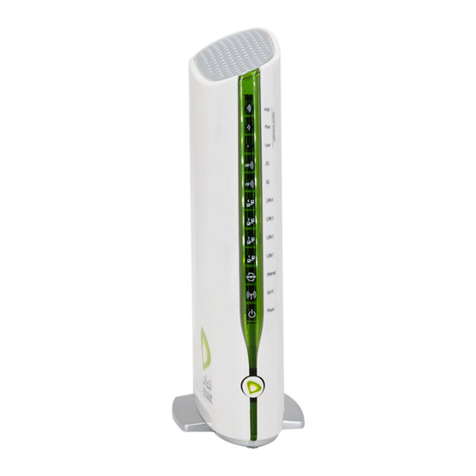
Etisalat HSPA User manual

Wireless Router
with voice
USER GUIDE
User Guide

2
Chapter-1
Preface
The purpose of this manual is to provide you with detailed information on the installation, operation and
application of your HSPA WiFi Router with Voice
Important Notice and Safety Precaution
• Before servicing or disassembling this equipment, always disconnect power from the device.
• Use an appropriate power supply, preferably the supplied power adapter, with an output of DC 12V 1.5A.
• Do not operate the device near flammable gas or fumes. Turn off the device when you are near a petrol
station, fuel depot or chemical plant/depot. Operation of such equipment in potentially explosive
atmospheres can represent a safety hazard.
• The device and antenna shall be used only with a minimum of 20 cm from the human body.
• The operation of this device may affect medical electronic devices, such as hearing aids and pacemakers.
• The Antennas must be connected to this product prior to connecting the telephone cord.
• The telephone cord must be disconnected prior to disconnecting the Antennas.
Thank You

3
Etisalat HSPA WiFi Router USER GUIDE
1– Introduction .......................................................................................................................................................................... 5
1.1 Features ......................................................................................................................................................................... 6
1.2 Package Contents ....................................................................................................................................................... 6
1.3 LED Indicators.............................................................................................................................................................. 7
1.4 Rear Panel..................................................................................................................................................................... 7
3– Web user Interface...........................................................................................................................................................8
3.1 Default Settings.......................................................................................................................................................... 9
3.2 Transmission Control Protocol/Internet Protocol (TCP/IP) Settings............................................................ 9
3.3 Login Procedure........................................................................................................................................................12
3.4 Web User Interface Homepage............................................................................................................................13
4– Etisalat Settings............................................................................................................................................................... 14
4.1 Etisalat Service Setup..............................................................................................................................................15
4.1.1 Profile Setup.................................................................................................................................................15
4.2 PIN Configuration ....................................................................................................................................................16
4.2.1 PIN Code Protection.................................................................................................................................. 16
4.2.2 PIN Code Change........................................................................................................................................17
5– Wireless...............................................................................................................................................................................18
5.1 Setup ............................................................................................................................................................................19
5.2 Security........................................................................................................................................................................20
5.3 Configuration ............................................................................................................................................................ 21
5.4 Media Access Control (MAC) Filter..................................................................................................................... 23
5.5 Wireless Bridge.......................................................................................................................................................... 23
5.6 Station Info................................................................................................................................................................ 24
6– Management.................................................................................................................................................................... 25
6.1 Device Settings..........................................................................................................................................................26
6.1.1 Backup Settings ..........................................................................................................................................26
6.1.2 Update Settings ..........................................................................................................................................26
6.1.3 Restore Default ...........................................................................................................................................26
6.1.4 Update Firmware ........................................................................................................................................27
6.2 Access Control...........................................................................................................................................................27
6.2.1 Services..........................................................................................................................................................27
6.2.2 IP Addresses..................................................................................................................................................28
6.2.3 Passwords ......................................................................................................................................................28
6.3 Configure SNMP agent on 3G10WVE ................................................................................................................ 29
6.4 Simple Network Time Protocol (SNTP)...............................................................................................................29
6.5 Save and Reboot.......................................................................................................................................................30
7– Advanced setup................................................................................................................................................................31
7.1 Local Area Network (LAN)......................................................................................................................................32
7.2 Network Address Translation (NAT) ....................................................................................................................33
7.2.1 Port Forwarding ..........................................................................................................................................33
7.2.2 Port Triggering............................................................................................................................................. 34
7.2.3 Demilitarized Zone (DMZ) Host..............................................................................................................34
7.3 Security.......................................................................................................................................................... 35
7.3.1 IP Filtering .................................................................................................................................................... 35
7.4 Routing........................................................................................................................................................................36
7.4.1 Default Router............................................................................................................................................. 36
7.4.2 Static Route..................................................................................................................................................37
7.4.3 Dynamic Route............................................................................................................................................37
7.5 Domain Name System (DNS) ................................................................................................................................ 37
7.5.1 Domain Name System (DNS) Server.....................................................................................................37
7.5.2 Dynamic Domain Name System (Dynamic DNS).............................................................................. 38
8– Voice .................................................................................................................................................................................... 39
8.1 Configuring your 3G10WVE for placing Voice Calls .....................................................................................40
9 – Status ................................................................................................................................................................................... 41
9.1 Diagnostics .................................................................................................................................................................42
9.2 System Log ................................................................................................................................................................. 43
9.3 Etisalat Status............................................................................................................................................................ 44
9.4 Statistics......................................................................................................................................................................46
9.4.1 LAN Statistics...............................................................................................................................................46
9.4.2 Etisalat Statistics ........................................................................................................................................ 47
9.5 Route............................................................................................................................................................................47
9.6 Address Resolution Protocol (ARP).....................................................................................................................48
9.7 Dynamic Host Configuration Protocol (DHCP)................................................................................................48
9.7 PING..............................................................................................................................................................................48
Appendix A: Print Server .................................................................................................................................................... 49
Appendix B: USB Storage ................................................................................................................................................... 56
Table of Contents

4
Etisalat HSPA WiFi Router USER GUIDE
With the increasing popularity of the 3G standard worldwide, the Etisalat HSPA WiFi Router with Voice provides you
with triple-band coverage through expanding cellular networks throughout the world.
Integrating a Sierra Wireless HSPA module, this Router is capable of performing at typical downlink speeds of
550Kbps to 3Mbps, bursting up to 6Mbps and typical uplink speeds of 300Kbps to 1Mbps, bursting to 1.3Mbps in
most places in the CBD, metro and other areas.
The Router also provides state-of-the-art security features such as WiFi Protected Access (WPA) data encryption,
Firewall and Virtual Private Networks (VPN) pass through.

Introduction
5
Chapter-1
Introduction

6
Etisalat HSPA WiFi Router USER GUIDE
1.1 Features
The Etisalat HSPA WiFi Router with Voice allows you to share your Etisalat connection with multiple wireless
or wired devices
Provides you with worldwide coverage through triple-band HSUPA/HSDPA/UMTS (850/ 1900 / 2100MHz),
quad-band EDGE/GSM (850/ 900 / 1800 MHz)
Embedded multi-mode HSUPA/HSDPA/UMTS/EDGE/GPRS/GSM module
1 x RJ11 port for voice calling over the Etisalat network via a connected standard Analogue Telephone (not
included).
Built-in USB 2.0 Print Server functionality
Support for USB 2.0 Mass Storage device (NTFS, FAT 32)
Integrated 802.11g/54Mbps AP (backward compatible with 802.11b)
WiFi Protected Access (WPA)/ WiFi Protected Access 2 (WPA2) and 802.1x wireless encryption
Static route/ Routing Information Protocol (RIP)/RIP v2 routing functions
Media Access Control (MAC) address and IP filtering
Network Address Translation (NAT) / Port Address Translation (PAT)
Supports Universal Plug and Play (UPnP) and Internet Group Management Protocol (IGMP) snooping
Supports Virtual Private Network (VPN) Pass-Through
Dynamic Host Configuration Protocol (DHCP) Server/Relay/Client
Domain Name System (DNS) Proxy and Dynamic Domain Name System (DDNS)
Web-based Management
Command Line Interface (CLI) via Telnet
Configuration backup and restoration
Remote configuration
Router and Etisalat module firmware upgrade
Supports half-bridging mode
Supports Simple Network Management Protocol (SNMP)
•
•
•
•
•
•
•
•
•
•
•
•
•
•
•
•
•
•
•
•
•
•
1.2 Package Contents
Your package contains the following:
Etisalat HSPA WiFi Router with Voice
Printed Quick Start Guide
CD (Containing User Guide)
Ethernet Cable
Security Card
2 x 3G Antennas
1 x WiFi Antenna
Power Supply
•
•
•
•
•
•
•
•
Introduction

7
Etisalat HSPA WiFi Router USER GUIDE
1.3 LED Indicators
The LED indicators are shown in this illustration and followed by detailed explanations in the table below.
LED Color Mode Description
POWER Green On Power on
Off Power off
Phone Green On Phone line active
Off Phone line inactive or not connected
LAN 1~2 Green On Powered device connected to the associated port (includes devices with wake-
on-LAN capability where a slight voltage is supplied to an Ethernet connection)
Off No activity, modem powered off, no cable or no powered device connected to
the associated port
Blink LAN activity present (traffic in either direction)
WiFi Green On Local WiFi access to the Router is enabled and working
Off Local WiFi access to the Router is disabled
Blink Data being transmitted or received over WiFi.
Internet Green Blink Data is transmitted through Internet connection
Off No connection to the internet or Router powered off
On Internet connection established
3G Green On Connection established with 3G network
Blink Connecting with 3G network
Off
No connection with UMTS cellular station, no activity, Router powered off.
2G Green On Connection established with 2G network
Blink Connecting to an EDGE, GPRS or GSM cellular station
Off
No connection with EDGE, GPRS or GSM cellular station, no activity or Router
powered off.
Low Green On Low signal strength
Off No activity, Router powered off or on other signal strength
Med Green On Medium signal strength
Off No activity, Router powered off or on other signal strength
High Green On High signal strength
Off No activity, Router powered off or on other signal strength
NOTE: The six LEDs on the left side of the top panel display (Low, Med, High, Internet, 3G, 2G) will cycle on and off if PIN
code protection is activated. In this case, you should consult section 3.2.1 PIN Code Protection (page 16) for further
instructions.
1.4 Rear Panel
The rear panel contains the ports for data and power connections.
(1) Power jack for DC power input (12VDC / 1.5A)/Power button
(2) USIM card slot
(3) USB Port (For connecting a USB Printer or USB Storage Device)
(4)Reset button
(5) Phone Port (for Voice calls over the Etisalat Network)
(6) 2 RJ-45 Ethernet LAN ports
Introduction
1 2 3 4 5 6 87
1 2 3 4 5 6 87
1 2 3 4 5 6 87
1 2 3 4 5 6 87
1 2 3 4 5 6 87
1 2 3 4 5 6 87

8
Interface
This section describes how to access the device via
the web user interface using a web browser such
as Microsoft Internet Explorer (version 5.0 or later),
Mozilla Firefox or Safari.
Chapter-2

9
Etisalat HSPA WiFi Router USER GUIDE
2.1 Default Settings
The following are the default settings for the Router
Local (LAN) access (username: admin, password: admin)
Remote (WAN) access (username: support, password: support)
User access (username: user, password: user)
LAN IP address: 192.168.1.1
Remote WAN access: disabled
NAT and firewall: enabled
Dynamic Host Configuration Protocol (DHCP) server on LAN interface: enabled
Technical Note:
During power on, the device initializes all settings to default values. It will then read the configuration profile from the
permanent storage section of flash memory. The default attributes are overwritten when identical attributes with different
values are configured. The configuration profile in permanent storage can be created via the web user interface or telnet
user interface, or other management protocols. The factory default configuration can be restored either by pushing the
reset button for more than five seconds until the power LED blinks or by clicking the Restore Default Configuration option
in the Restore Default Settings screen (see section 5.1.3).
•
•
•
•
•
•
•
2.2 TCP/IP Settings
It is likely that your computer will automatically obtain an IP Address and join the network. This is because the
Dynamic Host Configuration Protocol (DHCP) server (on the device) will start automatically when your Router
powers up.
This automatic assignment requires that DHCP is configured on your computers. It is likely that this is already the
case, but should you be required to configure this, please see the instructions below.
Windows XP
DHCP Mode
To set your PC for DHCP mode, check the Internet Protocol properties of your Local Area Connection. You can set
your PC to DHCP mode by selecting Obtain an IP address automatically in the dialog box shown below.
Web User Interface

10
Etisalat HSPA WiFi Router USER GUIDE
STATIC IP Mode
The following steps show how to configure your PC IP address using subnet 192.168.1.x. The following assumes
you are running Windows XP.
1: From the Network Connections window, open Local Area Connection (You may also access this screen by
double-clicking the Local Area Connection icon on your taskbar). Click the Properties button.
2: Select Internet Protocol (TCP/IP) and click the Properties button. The screen should now display as below.
Change the IP address to the domain of 192.168.1.x. (1<x<254) with subnet mask of 255.255.255.0. Set
the default Router and DNS server to the Router’s IP address.
NOTE: The IP address of the Router is 192.168.1.1. (default), so the PC must be set with a different IP. In the case
below, the PC’s IP address is set as 192.168.1.2
3: Click OK to submit the settings.
Web User Interface
MAC O S X 10 . 4
DHCP Mode
To set your Apple Mac for DHCP mode, browse to the Apple menu and select System Preferences. In the System
Preferences menu, click on the Network icon and select Ethernet. Next select Using DHCP from the Configure
drop down list. After clicking Apply, your Mac’s IP Address will now be automatically assigned from the Router.

11
Etisalat HSPA WiFi Router USER GUIDE
Web User Interface
STATIC Mode
If you do not wish to use automatic assignment of IP Addresses and wish to configure your Router manually,
your computer must have a static IP address within the Router’s subnet. The following steps show how to
configure your computer’s IP address within the subnet 192.168.1.x
1. Browse to the Apple menu and select System Preferences. From the System Preferences, click the Network
icon and select the Ethernet connection.
2. From the Configure drop down list, you can set your computer to Static IP mode by selecting the Manually
option.
3. Choose an IP address between 192.168.1.2 – 192.168.1.254 (Do not choose the Router IP of 192.168.1.1).
Enter this IP address into the field marked IP Address, and enter a Subnet Mask of 255.255.255.0
4. Set the Router and DNS server field to 192.168.1.1 (The Router’s IP address).
NOTE: The IP address of the Router is 192.168.1.1. (default), so the computer must be set with a different IP to the Router.In
the case below, the PC’s IP address is set as 192.168.1.2
5. Click Apply to submit the settings.
Windows Vista
DHCP Mode
To set your PC for DHCP mode, click properties of your Local Area Connection. You can set your PC to DHCP
mode by selecting Obtain an IP address automatically in the dialog box shown below.

12
Etisalat HSPA WiFi Router USER GUIDE
STATIC IP Mode
To configure your Router manually, your PC must have a static IP address within the Router’s subnet. The
following steps show how to configure your PC IP address using subnet 192.168.1.x. The following assumes you
are running Windows Vista.
1: From Control panel select the Network and sharing center, open Local Area Connection (You may also
access this screen by double-clicking the Local Area Connection icon on your taskbar). Click the Properties
button.
2: Select Internet Protocol (TCP/IPv4) and click the Properties button. The screen should now display as below.
Choose an IP address between 192.168.1.2 – 192.168.1.254
NOTE: The IP address of the Router is 192.168.1.1. (default), so the PC must be set with a different IP. In the case
below, the PC’s IP address is set as 192.168.1.2
3: Set the Router and DNS server field to 192.168.1.1 (The Router’s IP address).
3. Click OK to apply the settings.
2.3 Login Procedure
To login to the web interface, follow the steps below:
NOTE: The default settings can be found in 3.1 Default Settings.
1: Open a web browser and enter the default IP address for the Router in the Web address field. In this
case http://192.168.1.1
NOTE: For remote access, use the WAN IP address shown on the WUI Homepage screen and login with remote username and
password.
2: A dialog box will appear, as illustrated below. Enter the default username and password, as defined in
section 2.1 Default Settings.
Click OK to continue.
NOTE: The login password can be changed later (see 6.2.3 Passwords)
3: After successfully logging in for the first time, you will reach this screen.
Web User Interface

13
Etisalat HSPA WiFi Router USER GUIDE
2.4 Web User Interface Homepage
The web user interface (WUI) is divided into two window panels, the main menu (on the top) and the display
screen (on the bottom). The main menu has the following options: Basic, HSPA/3G Settings, WIFI, Management,
Advanced Settings and Status.
Selecting one of these options will open a submenu with more options. Basic is discussed below while
subsequent chapters introduce the other main menu selections.
NOTE: The menu options available within the web user interface are based upon the device configuration and user privileges
(i.e. local or remote).
BASIC
The Basic screen is the WUI homepage and the first selection on the main menu. It provides information
regarding the firmware, 3G, and IP configuration.
The following table provides further details.
Fields Description
Software version The software version of the device.
Hardware version The Hardware version of the device
Bootloader version The bootloader version of the device.
Wireless driver
version
The wireless driver version of the wireless module.
Network The name of or other reference to the mobile network operator.
Link Shows the connection status of the current Etisalat connection.
Mode The radio access technique currently used to enable internet access. It can be HSUPA,
HSDPA, UMTS, EDGE, GPRS or Disconnected.
Signal strength The mobile network (UMTS or GSM) signal quality available at the device location. This
signal quality affects the performance of the unit. If two or more bars are green, the
connection is usually acceptable.
SIM info Shows the SIM card status on the device.
LAN IP Address Shows the IP address for LAN interface.
WAN IP Address Shows the IP address for WAN interface.
Default Router Shows the IP address of the default Router for the WAN interface.
Primary DNS
Server
Shows the IP address of the primary DNS server.
Secondary DNS
server
Shows the IP address of the secondary DNS server.
Date/Time The time according to the device’s internal clock
Web User Interface

14
Settings
This menu includes HSPA/3G
Settings and PIN Conguration.
Chapter-3

15
Etisalat HSPA WiFi Router USER GUIDE
NOTE: Sections 8.3 and 8.4.2 also provide information about the Etisalat service.
3.1 HSPA/3G Settings
Select your HSPA/3G settings according to predefined or custom profiles.
Setup instructions are provided in the following sections for your assistance.
3.1.1 ProleSetup
Etisalat will provide the information required to complete the first time setup instructions below. Only complete
those steps for which you have information and skip the others.
1. If your SIM card is not inserted into the Router, please turn the Router off. Then insert the SIM and
turn the Router on.
2. To connect to Etisalat’s 3G network, please select the Etisalat profile with Etisalat’s APN as
etisalat.ae. Authentication Method should be provided by Etisalat; or just leave it AUTO if not
acquired. If you have not received the username and password, leave these fields empty.
3. Select IP compression and Data compression to be ON or Off. By default they are set to off.
4. Click the Save button to save the new settings.
5. Press the Connect button to connect to Internet. The Device Info for 3G network box in the WUI Basic
screen should indicate an active connection, as shown below. The 3G and Internet LEDs on the front
panel of the Router should also be blinking.
.
If the LEDs are off, then either your profile settings are incorrect, the SIM card is not working or the service
network is unavailable. In either case, contact Technical Support for further instructions.
NOTE: If the LEDs light in an on/off pattern moving from left to right this indicates that your SIM is PIN Locked, please see
PIN Lock Off on page 16 for instruction on how to fix this
Settings

16
Etisalat HSPA WiFi Router USER GUIDE
3.2 PIN Configuration
This screen allows for changes to the 3G SIM card PIN code protection settings.
NOTE: If you have entered the incorrect PIN 3 times, your SIM card will be locked for your security. Please call Etisalat for
assistance.
3.2.1 PIN Code Protection
PIN code protection prevents the use of a SIM card by unauthorized persons. To use the 3G internet service with
this Router however, the PIN code protection must be disabled. If the SIM card inserted into the Router is locked
with a PIN code, the web user interface will display the following screen after login.
PIN Lock Off
If you wish to connect to the Internet using a PIN locked SIM card, you must first turn PIN code protection Off.
Select PIN lock Off, enter the PIN Code twice. Please keep in mind you only have 3 attempts before your SIM
card is locked. The remaining attempts’ number shows how many attempts left. Contact Etisalat if you require
assistance. You can select Remember PIN Code to ON so you don’t need to input the PIN code every time when
the Router turns on. Afterwards, click Apply. The following dialog box should now appear.
PIN Lock On
After you are finished using your SIM card for Internet service, you may wish to lock it again. In this case, first
go to the 3G Settings - PIN Configuration screen, as shown below. Select PIN lock ON, enter the PIN code twice.
You can select Remember PIN code to Yes so you don’t need to input the PIN code every time when the Router
turns on. Then click Apply.
After you do so, the following dialog box should appear.
You can now return your SIM card to your cellular phone or other mobile device.
Settings

17
Etisalat HSPA WiFi Router USER GUIDE
3.2.2 PIN Code Change
If you wish to change your PIN code for greater security, enable the PIN Code protection. Go to the previous
section and follow the procedure listed under PIN Lock On.
After locking the SIM card, select PIN Code Change and enter your Old and New PIN codes in the fields
provided. Keep in mind you only have 3 attempts before your SIM card is locked. The remaining attempts’
number shows how many attempts left. Contact Etisalat if you require assistance. Afterwards, click Apply to
activate the change.
NOTE: IfyouforgettochangethePINCodewithoutrstturningonPINlockprotection,youwillseethisdialog
box as a helpful reminder.
NOTE: If your PIN Code change request was successful the following dialog box will display.
Settings

18
Wireless
The WIFI submenu provides access to Wireless Local
Area Network (LAN) conguration settings
Chapter-4

19
Etisalat HSPA WiFi Router USER GUIDE
4.1 Setup
This screen allows you to configure basic features of the wireless LAN interface. You can enable or disable the
wireless LAN interface, hide the network from active scans, set the wireless network name (also known as SSID)
and restrict the channel set based on country requirements. The Wireless Guest Network function adds extra
networking security when connecting to remote hosts.
Option Description
Enable Wireless A checkbox that enables (default) or disables the wireless LAN interface. When selected,
the Web UI displays Hide Access point, SSID, BSSID and Country settings.
Hide Access
Point
Select Hide Access Point to protect the access point from detection by wireless active
scans. To check AP status in Windows XP, open Network Connections from the start
Menu and select View Available Network Connections. If the access point is hidden, it
will not be listed there. To connect a client to a hidden access point, the station must
add the access point manually to its wireless configuration.
SSID
[1-32 characters]
Sets the wireless network name. SSID stands for Service Set Identifier. All stations must
be configured with the correct SSID to access the WLAN. If the SSID does not match,
that user will not be granted access.
BSSID The BSSID is a 48bit identity used to identify a particular BSS (Basic Service Set) within
an area. In Infrastructure BSS networks, the BSSID is the MAC (Media Access Control)
address of the AP (Access Point) and in Independent BSS or ad hoc networks, the BSSID
is generated randomly.
Country A drop-down menu that permits worldwide and specific national settings.
Wireless Guest
Network
The Guest SSID (Virtual Access Point) can be enabled by selecting the Enable Wireless
Guest Network checkbox. Rename the Wireless Guest Network as you wish.
NOTE: Remote wireless hosts cannot scan Guest SSIDs.
Wireless

20
Etisalat HSPA WiFi Router USER GUIDE
4.2 Security
This Router includes a number of options to help provide a secure connection to the Etisalat Network.
Security features include:
WEP / WPA / WPA2 data encryption
SPI Firewall
VPN Pass-Through
MAC address IP filtering
Authentication protocols – PAP / CHAP
You can authenticate or encrypt your service on the WiFi Protected Access algorithm, which provides protection
against unauthorized access such as eavesdropping.
The following screen appears when Security is selected. The Security page allows you to configure security
features of your Router’s wireless LAN interface. You can set the network authentication method, select data
encryption, specify whether a network key is required to authenticate to this wireless network and specify the
encryption strength.
Click Save/Apply to configure the wireless security options.
•
•
•
•
•
Option Description
Select SSID Your Service Set Identifier (SSID), sets your Wireless Network Name. You can connect
multiple devices including Laptops, Desktop PCs and PDAs to your HSPA WiFi Router with
Voice. To get additional devices connected, scan for a network, and locate the SSID shown
on your Wireless Security Card. If the SSID does not match, access is denied.
Network
Authentication
This option is used for authentication to the wireless network. Each authentication type
has its own settings as illustrated below. For example, selecting 802.1X authentication will
reveal the RADIUS Server IP address, Port and Key fields.
WEP Encryption will also be enabled.
The settings for WPA authentication are shown below.
WPA-Pre-
Shared Key
It is useful for small places without authentication servers such as the network at home. It
allows the use of manually-entered keys or passwords and is designed to be easily set up
for home users.
Wireless
Table of contents
Other Etisalat Wireless Router manuals

