Etlin-Daniels WP42M Series User manual

IMPORTANT: SAVE THESE INSTRUCTIONS FOR FUTURE REFERENCE
WARNING
PLEASE READ ALL INSTRUCTIONS BEFORE ATTEMPTING INSTALLATION.
• To reduce the risk of death, personal injury or property damage from fire, electric shock, falling parts,
cuts/ abrasions, and other hazards please read all warnings and instructions included with and on the
fixture box and all fixture labels.
• This installation should only be performed by a qualified electrician in accordance with the
National Electrical Code and all relevant local codes.
• Maintenance of the luminaires should be performed by person(s) familiar with the luminaires’ construction
and operation and any hazards involved. Regular fixture maintenance programs are recommended.
• It will occasionally be necessary to clean the outside of the refractor/lens. Frequency of cleaning will
depend on ambient dirt level and minimum light output which is acceptable to user. Refractor/lens
should be washed in a solution of warm water and any mild, non-abrasive household detergent, rinsed
with clean water and wiped dry. Should optical assembly become dirty on the inside, wipe refractor/lens
and clean in above manner, replacing damaged gaskets as necessary.
• DO NOT INSTALL DAMAGED PRODUCT! This luminaire has been properly packed so that no parts should
have been damaged during transit. Thoroughly inspect the fixture for any freight damage; freight
damage should be reported to the delivery carrier.
• WARNING: RISK OF ELECTRIC SHOCK. Make sure power supply is OFF before installing or maintaining
fixture. No user serviceable parts inside.
• Verify that supply voltage is correct by comparing it with the luminaire label information.
• The fixtures must be wired in accordance with the National Electrical Code and all applicable local
codes. Proper grounding is required for safety.
• All wiring connections should be capped with UL approved recognized wire connectors.
• CAUTION: RISK OF INJURY. Never perform maintenance or cleaning while fixture is energized.
Disconnect power and allow fixture to cool before maintaining.
• Do not exceed maximum wattage marked on luminaire label.
• Follow all manufacturer’s warnings, recommendations and restrictions for: driver type, burning position,
mounting locations/methods, replacement and recycling.
INSTALLATION FOR LED WALL PACK WP42M SERIES
Head Of ce - 1850 Wilson Ave. · Toronto, ON · M9M 1A1 · Tel: 416.741.7336 · Fax: 416.741.9104
Toll Free: in Canada. 1.800.661.9610 · in USA. 1.888.762.5384 (SOCKETS4U)
• Wear gloves and safety glasses at all times when removing luminaire from carton, installing, servicing or
performing maintenance.
• CAUTION: RISK OF FIRE. Keep combustible and other materials that can burn, away from lamp/lens.
• Do not operate in close proximity to persons, combustible materials or substances affected by heat or drying.
• CAUTION: RISK OF PRODUCT DAMAGE. Never connect components under load.
• Do not mount or support these fixtures in a manner that can cut the outer jacket or damage wire insulation.
• Controls for dimming, auto-sensing, or remote control of a luminaire that are not factory-wired to the
luminaire must be checked for compatibility with the luminaire prior to installation. Never connect an
LED product directly to a dimmer pack that has not been pre-approved. LED fixtures must be powered
directly off a switched circuit.
• Unless individual product specifications deem otherwise: do not restrict fixture ventilation. Allow for
some volume of airspace around fixture. Avoid covering LED fixtures with insulation, foam, or other
material that will prevent convection or conduction cooling.
• Unless individual product specifications deem otherwise: do not exceed fixture maximum ambient temperature.
• Only use fixture in its intended location.
• LED products are Polarity Sensitive. Ensure proper Polarity before installation.
• Electrostatic Discharge (ESD): ESD can damage LED fixtures. Personal grounding equipment must be
worn during all installation or servicing of the unit.
• Do not touch individual electrical components as this can cause ESD, shorten lamp life, or alter performance.
• Some components inside the fixture may not be serviceable. In the unlikely event your unit may require
service, stop using the unit immediately and contact your sales representative for assistance.
• User should prepare necessary accessories and spare parts (not provided) including junction box, cross
bar, junction box gasket, surface plate and screws.
• Always read the fixtures complete installation instructions prior to installation for any additional fixture
specific warnings.
Wiring
Wire input end of the LED driver to supply wires using appropriate wire nut according to
wiring section. Wire connections must be insulated and waterproof.
1. Connect the Black / Brown lead to LINE(+) supply lead.
2. Connect the WHITE / BLUE lead to NEUTRAL / COMMON (-) supply lead.
3. Connect the GREEN leads of front housing and back housing to GROUND supply lead.
4. For 0-10V dimming, use purple (+) and grey (-) wires.
BLACK / BROWN = HOT / LINE
WHITE / BLUE = NEUTRAL / COMMON
GREEN / YELLOW = GROUND
Purple (+) // Grey (-)
ELECTRICAL
SYSTEM
0-10V DIMMING
SYSTEM (IF ANY)
CAUTION: INTENDED APPLICATION
Input Voltage: 120-277V / 347V. 50/60Hz
CHECK PRODUCT LABEL RATINGS BEFORE ATTEMPTING INSTALLATION.
MIN. 90°C supply connectors
Operating temperature: -30°C to +40°C
Suitable for wet location
Mounting height: above 4’ (1.2 m)
Head Ofce - 1850 Wilson Ave. · Toronto, ON · M9M 1A1 · Tel: 416.741.7336 · Fax: 416.741.9104
Toll Free: in Canada. 1.800.661.9610 · in USA. 1.888.762.5384 (SOCKETS4U)
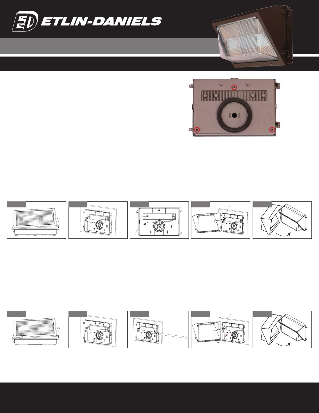
B: Conduit Mount Installation
1. Loosen screws on the right side of the fixture to open the fixture. Disconnect the quick connector (between LED module and LED driver) inside the fixture and take off the front housing.
2. Fix the back housing and secure it onto the wall. Refer to “product information bulletin” for more details. Gasket on back housing should create seal against wall surfaces,
you may use silicon sealant (not provided) to ensure tight seal against surface.
3. Remove the 1/2” plug from the side of the fixture and feed the conduit into the back housing through the knockout. Make wiring connection according to wiring selection. Refer to
“Wiring” for more details. Liquid tight connector required.
4. Attach the front housing back on the back housing. Re-connect the quick connector back.
5. Screw two bolts to tighten and close the fixture. Make sure all gaskets seated properly and all bolts and screws inserted and tightened firmly. Use silicone sealant (not provided)
all along the bottom of the fixture to ensure tight seal against surface.
IMPORTANT: SAVE THESE INSTRUCTIONS FOR FUTURE REFERENCE
INSTALLATION FOR LED WALL PACK WP42M SERIES
A: Wall Mount Installation
1. Loosen screws on the right side of the fixture to open the fixture. Disconnect the quick connector (between LED module and LED driver) inside the fixture and take off the front housing.
2. Open the back knockout on the back housing, and fix the housing and secure it onto the junction box inside the wall. Refer to “PRODUCT INFORMATION BULLETIN” for more details.
Junction box gasket should create seal against wall surface. On uneven surfaces, you may use silicon sealant (not provided) to ensure tight seal against surface.
3. Make wiring connection according to wiring selection. Refer to “WIRING” for more details.
4. Attach the front housing back on the back housing. Re-connect the quick connector back.
5. Screw two bolts to tighten and close the fixture. Make sure all gaskets seated properly and all bolts and screws inserted and tightened firmly.
Use silicone sealant (not provided) all along the bottom of the fixture to ensure tight seal against surface.
Product Information Bulletin
Use the drill and knockout template found on the inside back surface of the fixture to match
most standard recessed junction boxes.
For more secure installation, bolt back plate to mounting surface using standoff’s as
indicated on following pictures.
Figure A:1 Figure A:3 Figure A:4Figure A:2 Figure A:5
Figure B:1 Figure B:3 Figure B:4Figure B:2 Figure B:5
Head Ofce - 1850 Wilson Ave. · Toronto, ON · M9M 1A1 · Tel: 416.741.7336 · Fax: 416.741.9104
Toll Free: in Canada. 1.800.661.9610 · in USA. 1.888.762.5384 (SOCKETS4U)
IMPORTANT: SAVE THESE INSTRUCTIONS FOR FUTURE REFERENCE
INSTALLATION FOR LED WALL PACK WP42M SERIES
Figure D:1 Figure D:3
Screw head
Wire Guard
The open side of the lock clip
shall face downside.
To prevent water
entry, the lock clip
must be between the
gasket and screw
head. Failure to do so
will void warranty.
Lock-clip
Gasket behind
the lock clip
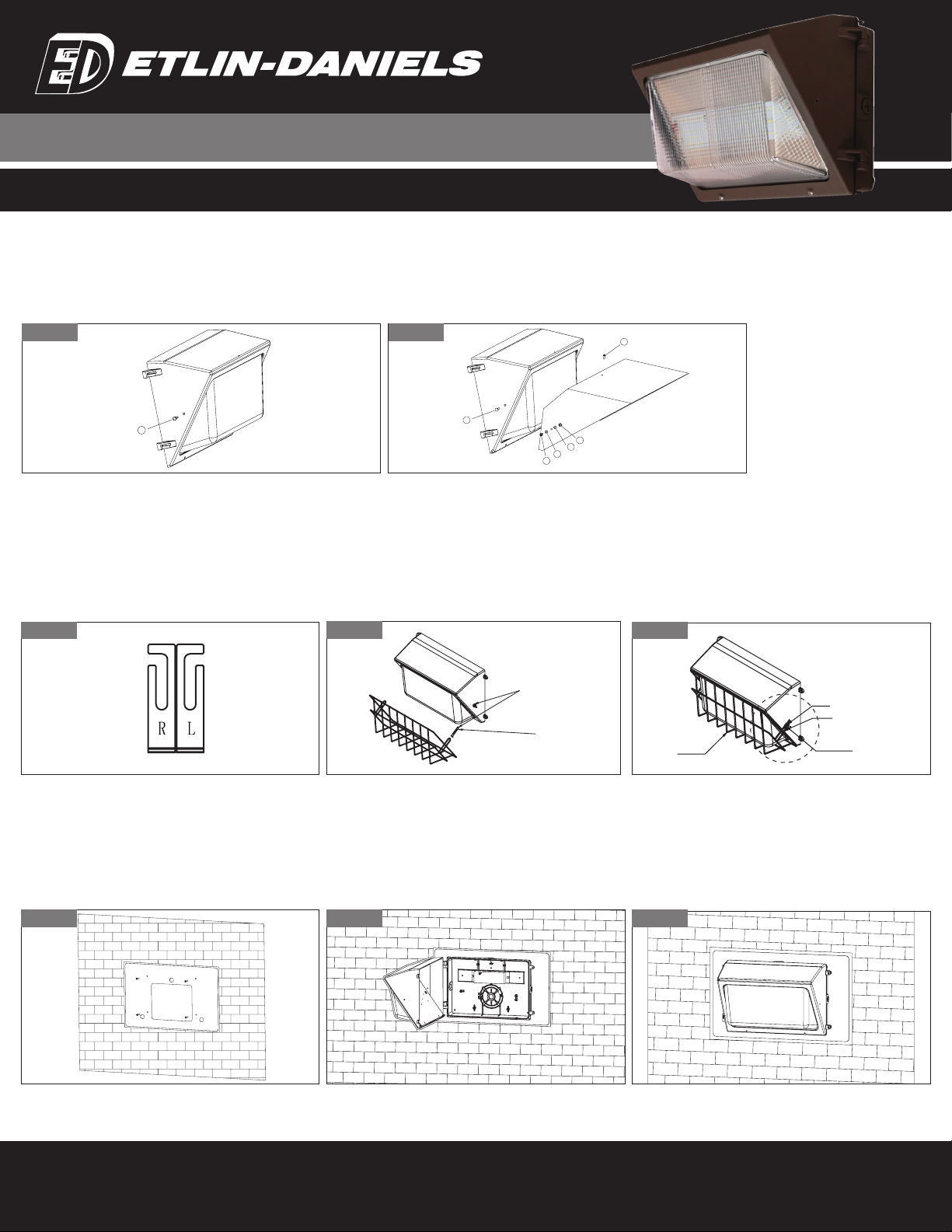
D: Wire Guard Installation
1. Separate the lock clips. Use the clip with “R” for right side and “L” for left side of wall pack. The open side of the lock clips should face downward while assembled.
2. Open the wall pack and loosen the screws on both sides.
Notice – when opening the rear housing, pay special attention and do not damage the spindle or inner wires
3. Insert the lock clip between the gasket and screw head. Hang the wire guard with the 2 ears on the lock clips. Adjust the lock clips to the correct position and tighten all screws.
Notice – make sure all screws are correctly tightened to prevent water entry. Failure to do so will void warranty.
4. Reassemble the front housing to back housing.
E: Vanity Plate Installation
1. Use the four holes on the vanity plate to mark exact locations of the screw holes on the wall. Drill holes accordingly to the marks into the wall, and insert the wall anchors into the holes.
2. Align the holes of the vanity plate with the holes on the wall. Tighten the screws into the holes to secure the vanity plate. Do not put upside down
3. Install wall pack fixture (14” housing) according to the footprint of vanity plate. Refer to “wall pack install instruction” for more details.
Use silicone sealant (not provided) all along the bottom of the fixture and vanity plate to ensure tight seal against surface.
Figure D:2
C: Visor Installation
1. Take off the 2 rubber inserts on both left and right side of the fixture.
2. Use the machine screws, nylon spacer and nuts (provided) to fix the visor on the fixture, total 3 pcs screws. Make sure the screws are tightly fixed.
Loosening of the screws may cause the visor to fall from the fixture and cause harm and damages.
Figure C:1 Figure C:2
1
BlackRubber
1
2
3
4
4
5
Black Rrubber
M4 *6mm Screw
M4 *10m m Screw
Nylon spacers
Nylon spacers
M4 Nuts
Figure E:2Figure E:1 Figure E:3
Other Etlin-Daniels Outdoor Light manuals

Popular Outdoor Light manuals by other brands

Clarke
Clarke SAL100B Assembly & operating instructions

Ingo Maurer
Ingo Maurer The MaMo Nouchies Wo-Tum-Bu 1 Mounting instructions

kuzco lighting
kuzco lighting EG45105 Installation sheet

Lampo
Lampo SPLEDSUPMC instruction manual

Quoizel
Quoizel SNNL8409K Assembly instruction sheet

Kitronik
Kitronik 2134 Build instructions

SWITCH MADE
SWITCH MADE CARA 20 user manual

Westgate
Westgate TC-WW-36W-RGBW-BT-BK Installation instructions manual

Farouk
Farouk CL1008 owner's manual

Orion
Orion AL 11-1208 Mounting and safety instructions

IMMAX
IMMAX neo LITE 07905L quick start guide

NORTHCLIFFE
NORTHCLIFFE ALGOL T LED Installation instruction


