Etlin-Daniels FLH5S-M Series User manual
INSTRUCTION
1 This fixture offers 3 types of dimming function.
2 Constant Current can be achieved by 0-10VDC and 1-10VDC dimming.
3 PWM (Pulse-Width Modulation) Signal dimming
4 Variance of resistance unit dimming
NOTE: Please choose the appropriate dimming way according to your needs.
You can also choose to ignore this function. Choose the wire connection option,
dimming option and install option according to your needs and the LED fixture
being installed.
ATTENTION
1. PLEASE VERIFY IF THERE IS ANY DAMAGE DURING SHIPPING.
If yes, please contact the manufacturer prior to starting installation.
2. Please read the installation guide carefully to check whether all accessories are
included. After confirmation, install the fixture according to Installation Steps.
Part No. Input Voltage Frequency Power Rated Current
FLH5S-M150WC0-5-PBS-DB
AC 120-347V 50/60Hz
100W/120W/150W 1.5A
FLH5S-M300WC0-5-PBS-DB 200W/250W/300W 3.0A
PARAMETERS
SAVE THESE INSTRUCTIONS - READ ALL INSTRUCTIONS CAREFULLY
WARNING
PLEASE READ ALL INSTRUCTIONS BEFORE ATTEMPTING INSTALLATION.
• Do not use any electrical generator to test LED fixture.
• To avoid risk of fire or electrical shock, this product should be installed and maintained by a
qualified electrician, in accordance with all national and regional electrical codes.
• Please turn off power before installation or maintenance.
• Proper earth grounding is required to ensure safety.
• After installation, ensure fixture is in correct vertical position.
• Please wear gloves to avoid injury during installation.
• If there is any presence of smoke or fire after installation, please turn off power immediately
and advise relevant personnel.
Head Ofce - 1850 Wilson Ave. · Toronto, ON · M9M 1A1 · Tel: 416.741.7336 · Fax: 416.741.9104
Toll free: in Canada. 1.800.661.9610 · in USA. 1.888.762.5384 (SOCKETS4U)
INSTALLATION FOR FLH5S-M HIGH WATTAGE FLOOD SERIES
CAN ICES-005 (B) / NMB-005 (B)
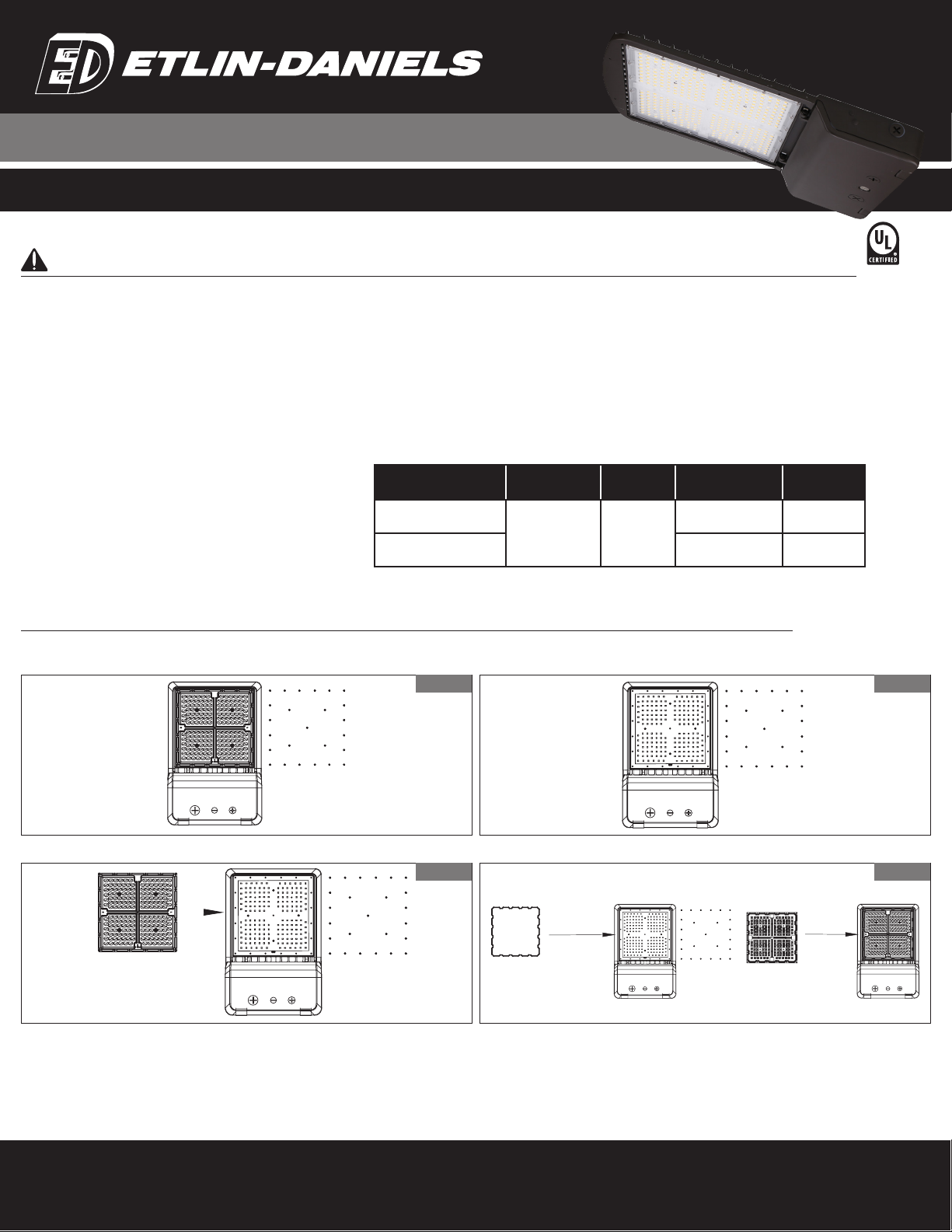
Installation of different NEMA Type Distribution Lenses
PLEASE IGNORE ALL LENS CHANGE INSTRUCTIONS IF YOU ARE NOT CHANGING THE NEMA BEAM PATTERN ORIGINALLY SUPPLIED.
1. Uninstall all screws from the existing lens.
3. Assemble the new lens and gasket.
2. Remove the original lens.
4. Screw in all screws when putting in new lens – maintain IP rating.
(Please note that lens changes should be performed prior to installing fixture). Note this fixture comes with a NEMA Type V Lens installed – Medium-wide distribution. We also offer optional
NEMA Type II, Type III and Type IV Lens options.
Figure 1
Figure 3
Figure 2
Figure 4
Head Ofce - 1850 Wilson Ave. · Toronto, ON · M9M 1A1 · Tel: 416.741.7336 · Fax: 416.741.9104
Toll free: in Canada. 1.800.661.9610 · in USA. 1.888.762.5384 (SOCKETS4U)
SAVE THESE INSTRUCTIONS - READ ALL INSTRUCTIONS CAREFULLY
INSTALLATION FOR FLH5S-M HIGH WATTAGE FLOOD SERIES
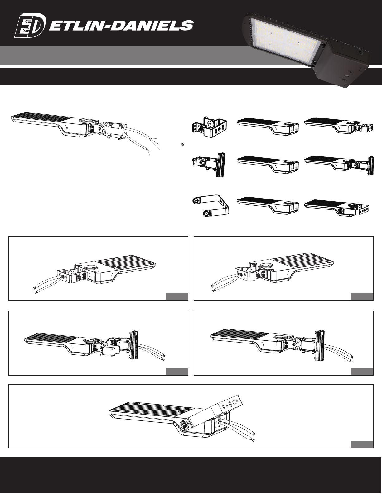
OPTIONAL MOUNTING BRACKETS
FLH5S-M-TR - Trunnion Mount
FLH5S-M-UM - Universal Mount
FLH5S-M-YM - Yoke Mount
WIRING DIAGRAM:
Black/Brown:ACL
Green/Yellow
White/Blue: ACN
Dim+
Dim-
As for the wire color
of DIM+ and DIM-,pls
check the lamp label.
1. Remove the bracket mounting screws on the fixture and pass the wires through
the bracket.
2. Install the bracket on the fixture.
Trunnion Bracket Mounting
Figure 1 Figure 2
1. Remove the bracket mounting screws on the fixture, open the side lid of the bracket and
pass the wires through the bracket.
1. Install 2 big screws.
2. Install 2 small screws.
2. Install the bracket on the fixture, cover the side lid and tighten screws.
Universal Bracket Mounting
Yoke Bracket Mounting
Figure 1 Figure 2
Figure 2

Head Ofce - 1850 Wilson Ave. · Toronto, ON · M9M 1A1 · Tel: 416.741.7336 · Fax: 416.741.9104
Toll free: in Canada. 1.800.661.9610 · in USA. 1.888.762.5384 (SOCKETS4U)
SAVE THESE INSTRUCTIONS - READ ALL INSTRUCTIONS CAREFULLY
INSTALLATION FOR FLH5S-M HIGH WATTAGE FLOOD SERIES
1. Drill holes on wall as shown.
1. Remove the 4 bolts from the Universal bracket and re-
move the 4 rubber plugs from the installation bar. Put the
4 rubber plugs in place where the 4 bolts were previously
installed for waterproof purposes.
2. Knock expansion bolts into wall.
2. Attach the Universal bracket to the square pole with
bolt, open the cover of the Universal bracket junction box,
pull wires into bracket junction box, connect the wires
properly and then cover the junction box. Adjust angle
(available 0-90˚ ).
3. Connect the fixture to the bracket and tighten the
screws. Connect wires properly and put all wiring into
junction box. Adjust angle (available 0-90˚ ).
3. Same on round pole installation – remember to use
adapting plate for round pole installation.
Adjust angle (available 0-90˚ ).
Trunnion Mounting
Universal Mounting - Direct Fitter Mounting
Figure 1
Figure 1
Figure 2
Figure 2
Figure 3
Figure 3
10
77 77
Expansion Bolt
YM Bracket light
±90°
1. Remove the spare parts from Universal bracket.
1. Install the Flood bracket to the fixture. Tighten the mount and install the screws.
2. Loosen the 4 bolts on the Universal bracket and connect the wires properly.
Pull wires through pole. Adust angle (available 0-90˚ ).
2. Tighten the screws and connect the wires properly. Place wires in junction box.
Universal Mounting - Adjustable Fitter Mounting
Yoke Mounting
Figure 1
Figure 1
Figure 2
Figure 2
cap
fixing Bolt
square pole
light
Round pole
A&D Bracket
Adapting plate
Loosen the angle to adjust the screw, after adjust
to the angle that you need, then tighten the screws.

1. This fixture comes equipped with the photocell base pre-installed. If photocell function is required, remove Shorting Cap from photocell base.
2. Install Photocell component. (Wiring – Load – Black/Brown // Neutral – White/Blue // Ground – Green/Yellow-Green. )
1. This fixture comes equipped with a pre-installed sensor base. If the sensor function is required, remove the ½” waterproof plug and install the sensor.
2. Follow sensor setting instructions (further in this guide).
1 This fixture provides for setting color temperature choice between 3000K / 4000K / 5000K. It also allows for a choice between 3 available wattages.
2 Unscrew the ¾” plug (see image below).
3 Adjust color temperature to required setting. Adjust wattage selection to proper setting.
4 Reinstall and tighten the ¾” plug.
Photocell Installation
Motion Sensor Installation
Color Temperature & Wattage Selection Adjustment
Head Ofce - 1850 Wilson Ave. · Toronto, ON · M9M 1A1 · Tel: 416.741.7336 · Fax: 416.741.9104
Toll free: in Canada. 1.800.661.9610 · in USA. 1.888.762.5384 (SOCKETS4U)
SAVE THESE INSTRUCTIONS - READ ALL INSTRUCTIONS CAREFULLY
INSTALLATION FOR FLH5S-M HIGH WATTAGE FLOOD SERIES
150W 120W 100W
300W 250W 200W
150W 120W 100W
300W 250W 200W

Head Ofce - 1850 Wilson Ave. · Toronto, ON · M9M 1A1 · Tel: 416.741.7336 · Fax: 416.741.9104
Toll free: in Canada. 1.800.661.9610 · in USA. 1.888.762.5384 (SOCKETS4U)
INSTALLATION FOR FLH5S-M HIGH WATTAGE FLOOD SERIES
BUTTON NAME DESCRIPTION
Voltage 12 ± 2VDC
Current <30mA
Output Dim 0-10V
Standby Power <0.5W
Brightness 0% -100% / Quick Setting: 70% / 80% / 90% / 100%
Sensitivity 20% / 50% / 75% / 100%
Hold Time 10s / 1 min / 10 min / 30 min
Daylight Threshold 10 Lux / 30 Lux / 50 Lux / 100 Lux / Disable
Standby Time 1 min / 30 min / 60 min / +∞
Standby Dimming
Level 10% / 20% / 30% / 50%
Microwave
Frequency 5.8GHz ± 75MHz
Microwave Power <0.5mW
Detection Angle 150°(wall mounted) / 360°(ceiling mounted)
Control Line Pink:+12V: Purple: Dim+; Gray:GND/Dim-
Mounting Height Max. 15m (ceilling mounted)
Detection Range Max.ø15m (ceilling mounted) Max. .ø20m (wall mounted)
Operating Temp -30°C~+60°C
IP Rating IP65
SENSOR WIRING DIAGRAM
SENSOR SPECIFICATION
CEILING MOUNTED
WALL MOUNTED
Adopted dual PD technology is able to differentiate artificial light brightness from natural
light after installed inside the fixture, and automatically turn off light when ambient
brightness exceeds preset lux level.
Preconditions to use the Lux-off function:
1. Standby period is + ∞;
2. Standby dimming level is on 10%, 20%, 30% or 50%
3. Daylight threshold is on 0Lux, 30Lux, 50Lux or 100Lux.
Head Ofce - 1850 Wilson Ave. · Toronto, ON · M9M 1A1 · Tel: 416.741.7336 · Fax: 416.741.9104
Toll free: in Canada. 1.800.661.9610 · in USA. 1.888.762.5384 (SOCKETS4U)
INSTALLATION FOR FLH5S-M HIGH WATTAGE FLOOD SERIES
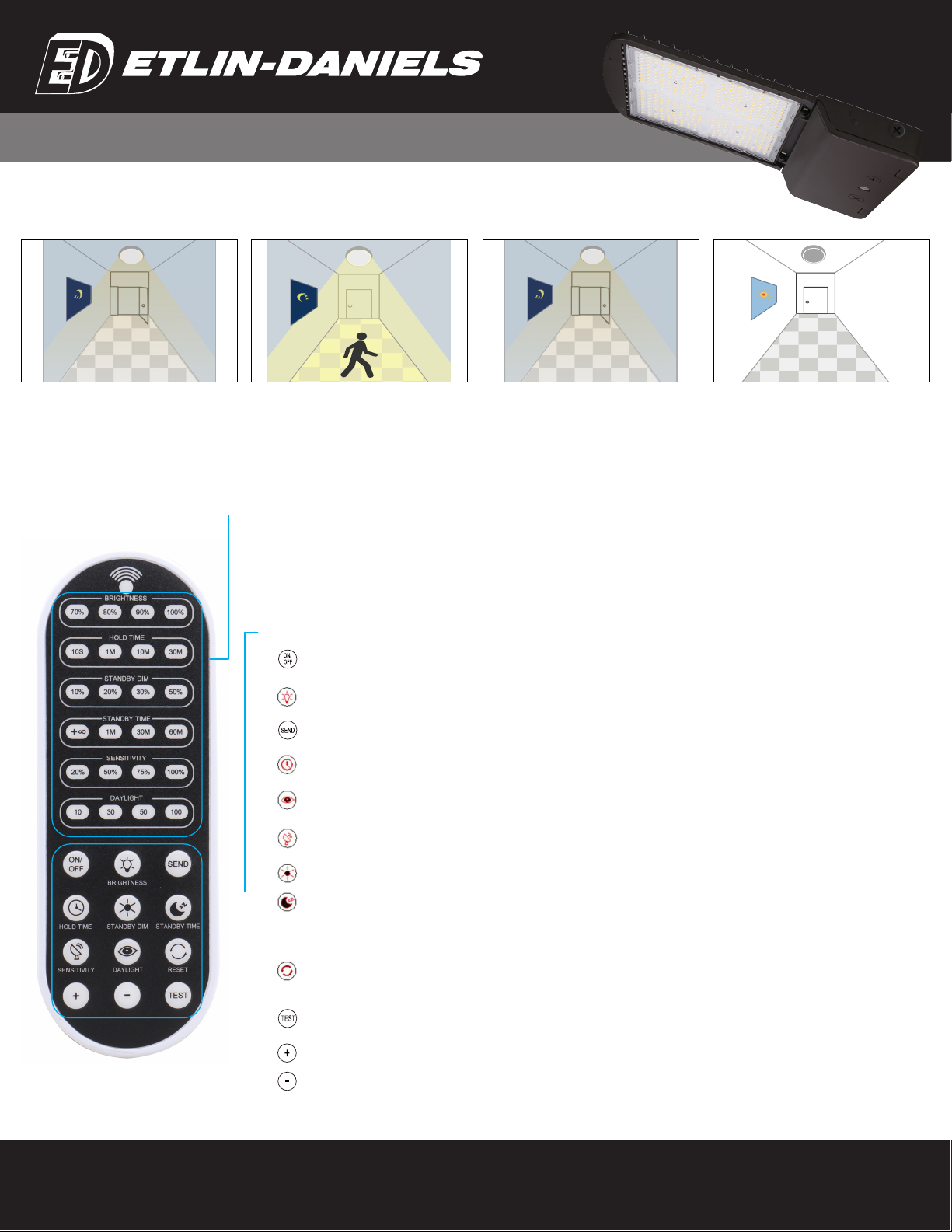
APPLICATION - LUX ON / OFF
Light off when ambient lux level is higher
than preset lux amount.
Light dims to standby level if no motion
detected after hold time.
Light automatically on when ambient
brightness is lower than preset lux level.
Display Area
Button Setting Area
Brightness (70% 80% 90% 100%)
Daylight (10lx / 30lx / 50lx / 100lx)
Standby Dim (10% 20% 30% 50%)
ON/OFF (Long press the “ON/OFF button until the brightness indicator light is on (First-row).
Press to turn on or tun off the fixture.)
BRIGHTNESS (Press to adjust dimming level 70% / 80% / 90% / 100%)
SEND (Press to save setting after each change. The indicator light confirms the save setting)
HOLD TIME (Press to hold time 10s / 1 min / 10 min / 30 min)
Press to increase brightness (0%-100%)
Press to reduce brightness (100%-0%)
STANDBY DIM (Press to adjust standby dimming level 10% / 20% / 30% / 50%)
STANDBY TIME (Press to adjust standby time + ∞/ 1 min / 30 min / 60 min)
Note: “+ ∞” means unlimited standby time, and the light control mode is the light control priority mode, otherwise it’s the light
threshold mode.
RESET (Press “RESET” button, products with DIP switch will be controlled by DIP switches; Otherwise all the setting will change,
which is Brightness 70% / Hold Time 10s / Sensitivity 20% / Daylight Threshold disabled / Standby Dimming Level 10% /
Standby Time + ∞
DAYLIGHT (Long press the button until the daylight indicator light is on, press to adjust daylight threshold
10lx / 30lx / 50lx / 100/x)
SENSITIVITY (Press to adjust sensitivity 20% / 50% / 75% / 100%) Note: PIR Motion Sensor have no sensitivity setting,
the default 100%.
TEST The button “TEST” is for testing purposes after debugging. Pressing the button, the sensor goes to test mode (hold time is
only 3s).
Hold Time (10S / 1 min / 10 min / 30 min)
Sensitivity (20% / 50% / 75% / 100% )
Standby Dim (+ ∞/ 1 min / 30 min / 60 min)
With insufficient ambient brightnes, light
dims to 100% when motion detected.
REMOTE CONTROL APPLICATIONS

Head Ofce - 1850 Wilson Ave. · Toronto, ON · M9M 1A1 · Tel: 416.741.7336 · Fax: 416.741.9104
Toll free: in Canada. 1.800.661.9610 · in USA. 1.888.762.5384 (SOCKETS4U)
INSTALLATION FOR FLH5S-M HIGH WATTAGE FLOOD SERIES
1. If you want to send a setting, it will only work if the remote is on. If you don’t press any button within 10 seconds, the indicator light will go out.
2. When using “ON / OFF” button, the rest buttons except the “ON / OFF”, “BRIGHTNESS“ and “SEND” buttons will be disabled.
3. When using “TEST” button, the rest buttons except the “TEST”, “SENSITIVITY” and “SEND” buttons will be disabled.
4. Every change needs to press “SEND” button, it will be saved.
5. Because of the power supply Dimming ratio difference, when using different power, “BRIGHTNESS” and “STANDBY DIM” adjust percentage of the power will have difference with the
measured power.
6. Light control priority mode: the “ON/OFF” illumination values of each gear are 10lx / 50lx, 30lx/100lx, 50lx/150lx and 100lx/200lx.
7. Light threshold mode: the “ON/OFF” illumination values of each gear is 10lx/30lx/50lx.100lx, when the light intensity is less than set value and the movement of someone or an object is
induced, the light is turned on to the preset brightness.
1. Remove the batteries from compartment if the remote will not be used in 30 days.
2. When setting, there should be no object blocking between the remote control and the sensor, otherwise the remote may fail to send data.
1. Because the control angle of infrared remote control is fixed, if the sensor installation distance is too close, the remote control will control two sensors at the same time.
2. When the installation height changes, the installation distance can be adjusted appropriately to avoid the adjacent sensors being controlled by the remote controller at the same time.
See the table below fo reference distance.
The remote control Wireless IR Configuration Tool is a handheld tool for remote configuration of IR-enabled fixture integrated sensors. The tool enables device to modify via push button
without ladders or tools.
The remote control uses IR communication to send sensor settings at mounting height up to 50 ft. The device can be display previously established sensor parameters. Send new parameter
profiles.
ATTENTION!
WARNING!
SCHEMATIC DIAGRAM OF REMOTE CONTROL RANGE
OVERVIEW
Mounting Height Sensor Mounting Distance
15m 4m
12m 3.2m
9m 2.4m
6m 1.6m
3m 0.8m
This manual suits for next models
2
Table of contents
Other Etlin-Daniels Outdoor Light manuals


