ETT McCheck ST-50 USB User manual

1646912
ETT Distribution GmbH Schmalbachstraße 16 38112 Braunschwei
Nachdruck oder Vervielfälti un nur mit ausdrücklicher Genehmi un Stand 12/2016
Techni
s
c
he
Daten
:
Gewicht: 202
Maße (H*B*T): 200*100*26 mm
Betrieb: 9 V Blockbatterie (6F22)
Steckertypen: RJ-11, RJ-45, IEEE 1394, BNC, USB
In der Lieferun enthalten:
1x Testkabel mit RJ-11-Steckern
1x Testkabel mit RJ-45-Steckern
1x Testkabel mit BNC-Steckern
1x BNC-Abschlusswiderstand
Bedienungsanleitung
Netzwerkkabeltester McCheck “ST-50 USB”
Einführung
Geehrter Kunde,
wir möchten Ihnen zum Erwerb Ihres
neuen Kabeltesters ratulieren!
Mit dieser Wahl haben Sie sich für ein Produkt
entschieden, welches ansprechendes Desi n
und durchdachte technische Features ekonnt
vereint.
Lesen Sie bitte die fol enden Bedienhinweise
sor fälti durch und befol en Sie diese, um in
mö lichst un etrübten Genuss des Gerätes zu
kommen!
Leistungsmerkmale
• Einfache Leitun süberprüfun Ihrer
Netzwerkinstallation.
• Der Meßempfän er ist separierbar, d.h. man
kann sowohl lose, als auch fest installierte Kabel
testen.
• Es kann die Verbindun mit Hilfe von
Leuchdioden auf Durch an , Unterbrechun ,
Kurzschluss, Masseverbindun , Termination und
auf ekreuzte Adern eprüft werden.
• Komfortable Eintastenbedienun , automatischer
Scanvor an und übersichtliches Anzei efeld.
Sicherheitshinweise
• Überprüfen Sie vor Inbetriebnahme das Gerät auf Beschädi un en, sollte dies der Fall sein, bitte das
Gerät nicht in Betrieb nehmen!
• Achtun : Mit diesem Tester dürfen nur spannun sfreie Kabel efprüft werden (Lebens efahr!).
• Entfernen Sie die Batterie, wenn Sie das Gerät län ere Zeit nicht nutzen wollen.
• Das Gerät keinen mechanischen Belastun un en, hohen Temperatauren oder Feuchti keit aussetzen.
• Reini en Sie das Gerät mit einem weichen trockenen Tuch.
• Wichti ! Sollten das Gerät einmal beschädi t werden, lassen Sie es nur durch den Hersteller oder eine
Fachwerkstatt instandsetzen.
• Lassen Sie das Verpackun smaterial nicht achtlos lie en, Plastikfolien / -tüten, Styroporteile, etc.,
könnten für Kinder zu einem efährlichen Spielzeu werden.
• Das Gerät ehört nicht in Kinderhände. Es ist kein Spielzeu .
1646912
ETT Distribution GmbH Schmalbachstraße 16 38112 Braunschwei
Nachdruck oder Vervielfälti un nur mit ausdrücklicher Genehmi un Stand 12/2016
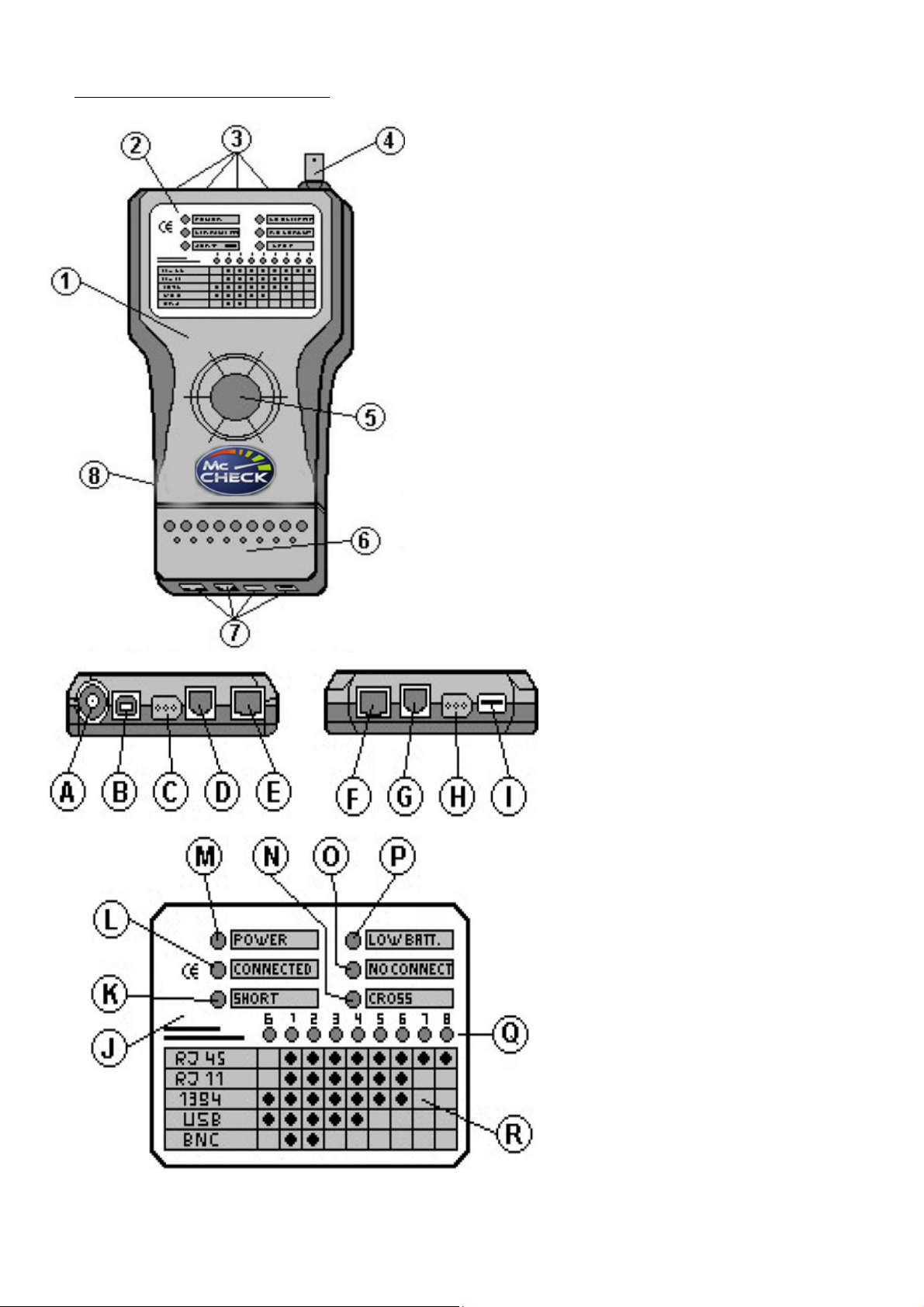
Das Gerät und seine Funktionen:
1. Kabeltester „ST-50 USB“.
2. Anzei efeld mit Leuchtdioden.
3. Aus an sbuchsen (RJ-11, RJ-45, IEEE 1394, USB).
4. Anschlussbuchse für BNC-Stecker.
5. Test-Schalter.
6. Remote Terminator (RT) mit Leuchtdioden.
7. Ein an sbuchsen des RT (RJ-11, RJ-45, IEEE 1394,
USB).
8. Batteriefach auf der Rückseite.
A. BNC-Anschlussbuchse.
B. USB-Anschlussbuchse (B-Stecker).
C. IEEE 1394-Anschlussbuchse (Firewire).
D. RJ-11-Anschlussbuchse.
E. RJ-45-Anschlussbuchse ( eschirmt).
F. RJ-45-Anschlussbuchse RT ( eschirmt).
G. RJ-11-Anschlussbuchse RT.
H. IEEE 1394-Anschlussbuchse RT (Firewire).
I. USB-Anschlussbuchse RT (A-Stecker).
J. Anzei efeld mit Leuchtdioden.
K. SHORT: Zei t bei Kurzschluss einer oder mehrerer
Adern an. Q zei t die betroffenen Adern durch blinken
an und es erklin en zwei Si naltöne.
L. CONNECTED: Zei t einwandfreie Verbindun bei 1:1
verdrahteten Kabeln an.
M. POWER: Betriebsanzei e.
N. CROSS: Zei t bei ekreuzten Adern an und es
erklin en 2 Si naltöne.
O. NO CONNECTION: Zei t bei BNC-
Abschlusswiderstand oder nicht
an eschlossenem RT an. Es
erklin t 1 Si nalton.
P. LOW BATT.: Zei t an, wenn die
Batterie zu schwach ist und ersetzt
werden muß.
Q. Anzei e der einzelnen Adern 1 – 8
und der Masseverbindun G.
R. Tabelle für Q mit der Adernanzei e
bezü lich des jeweili en Kabeltyps,
falls die Verbindun sleitun intakt
ist.

1646912
ETT Distribution GmbH Schmalbachstraße 16 38112 Braunschwei
Nachdruck oder Vervielfälti un nur mit ausdrücklicher Genehmi un Stand 12/2016
Betrieb:
Achtun : Das Prüfen von Kabeln mit dem Kabeltester darf nur im spannun sfreien Zustand der Kabel
durch eführt werden. Vor jeder Messun ist die Spannun sfreiheit sicherzustellen, d.h. bei Messun en an
installierten Kabeln darf der Verbraucher nicht an eschaltet sein (Lebens efahr!).
Fü en Sie die Batterie in das Test erät ein, welches damit betriebsbereit ist.
Das Testen on RJ-11- und RJ-45-Kabeln:
• Verbinden Sie eine Seite des Kabels mit dem RJ-11- [D] bzw. dem RJ-45-Anschluss [E] des Testers und
die andere an RT [G] bzw. [F]. Falls es sich um ein fest installiertes Kabel handeln sollte, kann man RT
vom Gerät lösen.
• Drücken Sie auf den Test-Schalter [5]. Nun leuchtet POWER [M] und der Meßvor an wird estartet.
• Jetzt prüft das Gerät alle Adern nacheinander ab. Dies wird jeweils durch Aufleuchten der Leuchtioden
von [Q] an ezei t und einem Si nalton an ezei t. Nicht bele te Adern erzeu en kein Si nal.
• Handelt es sich um ein ab eschirmtes Kabel, leuchtet zusätzlich die Diode G auf.
• Nach erfol reicher Messun eines 1:1 Kabels ohne edrehte Adern leuchtet CONNECTED [L] und alle
bele ten Leuchtdioden von [Q] für 5 s permanent auf.
• Wenn die Adern im Kabel edreht sind leuchtet CROSS [N] und alle bele ten Leuchtdioden von [Q] für 5
s permanent auf.
• Bei Kurzschluss einzelner Adern leuchtet SHORT [K] und die Leuchtdioden von [Q] der betroffenden
Adern zei en nicht an. Auch das diese Anzei e erlischt nach 5 s.
Das Testen on USB- und IEEE 1394-Kabeln:
• Verbinden Sie eine Seite des Kabels mit dem USB- [B] bzw. dem IEEE 1394-Anschluss [C] des Testers
und die andere RT [I] bzw. [H]. Falls es sich um ein fest installiertes Kabel handeln sollte, kann man RT
vom Gerät lösen.
• Drücken Sie auf den Test-Schalter [5]. Nun leuchtet POWER [M] und der Meßvor an wird estartet.
• Jetzt prüft das Gerät alle Adern nacheinander ab. Dies wird jeweils durch Aufleuchten der Leuchtioden
von [Q] an ezei t und einem Si nalton an ezei t. Nicht bele te Adern erzeu en kein Si nal.
• Handelt es sich um ein ab eschirmtes Kabel, leuchtet zusätzlich die Diode G auf.
• Nach erfol reicher Messun eines 1:1 Kabels ohne edrehte Adern leuchtet CONNECTED [L] und alle
bele ten Leuchtdioden von [Q] für 5 s permanent auf.
• Wenn die Adern im Kabel edreht sind leuchtet CROSS [N] und alle bele ten Leuchtdioden von [Q] für 5
s permanent auf.
• Bei Kurzschluss einzelner Adern leuchtet SHORT [K] und die Leuchtdioden von [Q] der betroffenden
Adern zei en nicht an. Auch das diese Anzei e erlischt nach 5 s.
Das Testen on BNC-Kabeln:
• Verbinden Sie eine Seite des Kabels mit dem BNC-Anschluss [A] des Testers und die andere mit dem
bei ele ten Abschlusswiederstand.
• Drücken Sie auf den Test-Schalter [5]. Nun leuchtet POWER [M] und der Meßvor an wird estartet.
• Jetzt prüft das Gerät alle Adern nacheinander ab. Dies wird jeweils durch Aufleuchten der Leuchtioden
von [Q] an ezei t und einem Si nalton an ezei t. Nicht bele te Adern erzeu en kein Si nal.
• Nach erfol reicher Messun leuchtet CONNECTED [L] und alle bele ten Leuchtdioden von [Q] für 5 s
permanent auf.
• Ist das Kabel defekt, findet keine Si nalüberta un statt.

1646912
ETT Distribution GmbH Schmalbachstraße 16 38112 Braunschwei
Nachdruck oder Vervielfälti un nur mit ausdrücklicher Genehmi un Stand 12/2016
Technical
S
pecifications
:
Wei ht: 202
Size (H*W*D): 200*100*26 mm
Operation: 9 V battery (6F22)
Connector Types: RJ-11, RJ-45, IEEE 1394, BNC,
USB
Included:
1x Test cable with RJ-11-plu s
1x Test cable with RJ-45-plu s
1x Test cable with BNC-plu s
1x BNC-dummy load
Reference Manual
Network Cable Tester McCheck „ST-50 USB“
Preface
Dear Customer,
we like to con ratulate you on the
purchase of your new cable tester!
You have chosen a product which
combines deliberate technical features
with an appealin desi n.
Please read this manual conscientiously
and carry out the iven instructions before
and while you are usin your new device.
Capability Characteristics
• Easy circuit check-up of your network cables.
• The remote tester is separable which means you
can check either connected as well as
disconnected cables.
• It is possible to check the connection with the
help of LEDs for passa e, open circuit, short
circuit, round, termination and crossin .
• Easy to use one-button operation, automatic
scannin and clearly arran ed display.
Security Ad ices
• Before usin the device, please check it for any possible dama es. In case of dama e do not operate it.
• Attention: Cables tested by this device must be de-ener ized (Life dan er!).
• Remove the battery when you do not use the device for a certain time.
• The device may not become subject of mechanical stress and should not be exposed to humidity or hi h
temperatures.
• Clean the device with a dry and soft cloth only.
• Caution! Should the device itself et dama ed, please let the repair to the manufacturer or to a qualified
service a ent.
• Please dispose packa in materials properly and do not let play children with it.
• The device itself is no toy either. Do not let children play with it too.

1646912
ETT Distribution GmbH Schmalbachstraße 16 38112 Braunschwei
Nachdruck oder Vervielfälti un nur mit ausdrücklicher Genehmi un Stand 12/2016
The De ice and its Functions:
1. Cabel tester „ST-50 USB“.
2. Display with LEDs.
3. Output connectors (RJ-11, RJ-45, IEEE 1394, USB).
4. Connector for BNC-plu .
5. Test-button.
6. Remote Terminator (RT) with LEDs.
7. Input connectors of the RT (RJ-11, RJ-45, IEEE
1394, USB).
8. Battery compartment on the backside.
A. BNC-connector.
B. USB-connector (B-plu ).
C. IEEE 1394-connector (Firewire).
D. RJ-11-connector.
E. RJ-45-connector (screened).
F. RJ-45-connector RT (screened).
G. RJ-11-connector RT.
H. IEEE 1394-connector RT (Firewire).
I. USB-connector RT (A-plu ).
J. Display with LEDs.
K. SHORT: Shows a short circuit in one or more leads.
Q shows the affected leads by flashin and two
acoustic si nals sound.
L. CONNECTED: Shows the proper connection of 1:1
wired cables.
M. POWER: Operation display.
N. CROSS: Shows in case of crossed leads and two
acoustic si nals sound.
O. NO CONNECTION: Shows in case of BNC-load
resistance or if the RT is not
connected. One acoustic si nal
sounds.
P. LOW BATT.: Shows when the battery
becomes weak and has to be
exchan ed.
Q. Display of each sin le lead 1 – 8 and
the round connection G.
R. Table for Q with the display of the
sin le leads referrin to the certain cable
type for the case that the connection is
faultless.

1646912
ETT Distribution GmbH Schmalbachstraße 16 38112 Braunschwei
Nachdruck oder Vervielfälti un nur mit ausdrücklicher Genehmi un Stand 12/2016
Operation:
Attention: For checkin cables with this device these must be de-ener ized. Prior to any measurement make
sure the cable is de-ener ized which means that the load must be switched off in case of installed cables (Life
dan er!).
Insert the battery into the cable tester which will make it ready for operation.
The Testing of RJ-11- and RJ-45-cables:
• Connect one side of the cable with the RJ-11- [D] and the RJ-45-connector [E] respectively of the tester
and the other one to RT [G] and [F] respectively. If the cable is firmly installed detach RT and use it as
a remote device.
• Press the test-button [5]. Now POWER [M] shows and the scannin is startin .
• Now the device checks all leads one after another. This is shown by illumination of the LEDs of [Q] and
an acoustic si nal. Leads which are not busy will not create a si nal.
• If the cable is screened additionally the LED G will show too.
• After a successful test on a 1:1 cable without crossed leads CONNECTED [L] shows and all busy LEDs of
[Q] are illuminated permanently for 5 s.
• If the cable has crossed leads CROSS [N] shows and all busy LEDs of [Q] are illuminated permanently
for 5 s.
• In case that one or more leads have a short circuit SHORT [K] shows and the LEDs of the affected leads
at [Q] will not showin . This display will also o off after 5 s.
The Testing of USB- and IEEE 1394-cables:
• Connect one side of the cable with the USB- [B] and the IEEE 1394-connector [E] respectively of the
tester and the other one to RT [I] and [H] respectively. If the cable is firmly installed detach RT and use
it as a remote device.
• Press the test-button [5]. Now POWER [M] shows and the scannin is startin .
• Press the test-button [5]. Now POWER [M] shows and the scannin is startin .
• If the cable is screened additionally the LED G will show too.
• After a successful test on a 1:1 cable without crossed leads CONNECTED [L] shows and all busy LEDs of
[Q] are illuminated permanently for 5 s.
• If the cable has crossed leads CROSS [N] shows and all busy LEDs of [Q] are illuminated permanently
for 5 s.
• In case that one or more leads have a short circuit SHORT [K] shows and the LEDs of the affected leads
at [Q] will not showin . This display will also o off after 5 s.
The Testing of BNC-cables:
• Connect one side of the cable with the BNC-connector [A] of the tester and stick the included BNC-
dummy load into the plu on the other side.
• Press the test-button [5]. Now POWER [M] shows and the scannin is startin .
• Press the test-button [5]. Now POWER [M] shows and the scannin is startin .
• After a successful test CONNECTED [L] shows and all busy LEDs of [Q] are illuminated permanently for
5 s.
• Defective cables will not create a si nal.
Table of contents
Languages:


