Eubiq SH1 User manual

FLOOR/HOME FIXTURE
Technical SpecificationPLEASE READ BEFORE INSTALLING
Keep away from fire.
Keep away from water.
Not for outdoor use.
To be installed by a
qualified electrician/
installer.
CAUTION
Backplate Guide
INSTALLING PARTY
All Power Tracks must be installed by a qualified
electrician.
USE OF EARTH LEAKAGE CIRCUIT BREAKER (ELCB)
It is a mandatory requirement that all installations of
electrical
power source must be connected to an ELCB to provide
protection against overload, short circuits and earth
leakages
faults. Failure to comply can be harzadous.
INSTALLATION LOCATION
All Power Tracks must be installed at location that
complies with safety rules and regulations of respective
country.
INSTALLATION SURFACE
All Power Tracks must be installed on flat surface.
RECOMMENDED INSTALLATION CLEARANCE
Refer to FIG.1 on the right for more information on the
minimum clearance (from the floor or any furniture
fixtures) required for ‘twist-on’ adaptors and accessories.
Prepare leads as shown:
10mm
10mm
50mm
40mm
1) Do not use in damp environment.
2) If in doubt, please consult a qualified electrician.
Live (Brown or Red)
Earth (Green or Green/Yellow)
Neutral (Blue or Black)
Product Orientation
V-GROOVE AT BOTTOM
SH1
Power and Data Track (With SFC3)
Installation Guide
Product Overview Wiring Instructions
Screw Cap
Pan Head Self Tapping Screw
SH1 End Cap
SH1 Internal Corner Cap
MF1 Mounting Frame
SH1 Corner Link
SH1 External Corner Cap
SH1 Housing
SFC3 Modular Track
DS4 Data Socket Housing
FIG. 1 Minimum Clearance for SH1 Installation
Minimum clearance of 25mm from the bottom required.
Housing Joint Pin
75mm
SFC Blank Cover
SH1 Retainer
25mm
Measurement Guide
ATTACHING ACCESSORIES*
5mm
Overall Wall Length
x
y
DESCRIPTION
For internal corner joint:
Width of gap = 37mm
Width of end cap = 5mm
MEASUREMENT GUIDE
FormulaSH1 Housing Length
(x - 37 - 5)mma
(y - 37)mmb
(z - 5)mmc
z
SH1 Housing
Length
a
b
c
End Cap
End Cap
* Compatible Accessories:
KH Kitchen Hook
KR Kitchen Rail
Live Terminal
Neutral TerminalLive and Neutral Indicator
Earth Terminal
SFC3 Track
For SFC3 Modular Track
Rated Voltage : 250V a.c. Single-phase
Rated Current : 32Amp maximum
Frequency : 50Hz / 60Hz
Rated Impulse Withstand Voltage : 4000V a.c.
Connection of Adaptor or
Tap-off Unit : Intended to be connected
and disconnected when
when system is energized
and with a load connected
Terminal Connecting Capacity
(Live, Neutral and Earth) : 1.25mm² to 6mm²
Ambient Operating Temperature : -5°C to +55°C (not to
exceed an average of more
than 35°C in any 24 hours
period)
Maximum Installation Altitude : 2000 metres
Degree of Protection : IP4X
Resistance to Impact : Heavy Impact
Degree of Pollution : 2 (Non-conductive pollution
with temporary conductivity
caused by condensation)
Track and Housing Material : Aluminium
Insulation Material : Polycarbonate
Internal Corner
Cap
External
Corner Cap
a
b
c
x
y
z5mm
5mm
37mm
DMK-005-016-03 ENG
SFC3 Track Length
< 400mm
400 - 600mm
601 - 1100mm
1101 - 1500mm
1501 - 2500mm
2501 - 3300mm
3
4
6
9
12
15
3
2-2
3-3
3-3-3
3-3-3-3
3-3-3-3-3
-
100mm
160mm
160mm
160mm
160mm
Quantity (Pcs) Arrangement
a (mm)
SFC3 Track
Housing
a a
*Where ais the length between the edge of the SFC3 Track to
the outermost edge of the backplate.
Attaching Multiple Backplates
Replace the end terminal
cover and fasten the screws.
End terminal cover with
cable entry blanks removed.
Terminate the wires to the
respective terminals.
Cut and remove the side and rear cable entry blanks from the
end terminal cover.
Loosen the screws with Philips
head screw driver, and remove
the end terminal cover.
Flip open and hold the soft flap in position. Insert the bit of
the flat head screw driver into the slot, push down at a 45°
angle to release the catch.
Insert the end terminal into
the anchor, pushing it all the
way until a ‘click’ sound is
heard to secure the end
terminal.
Refer to SFC3 Guide
(DMK-005-023) for steps to
attach backplates.
13
24
DMK-005-016-03 ENG
Installation
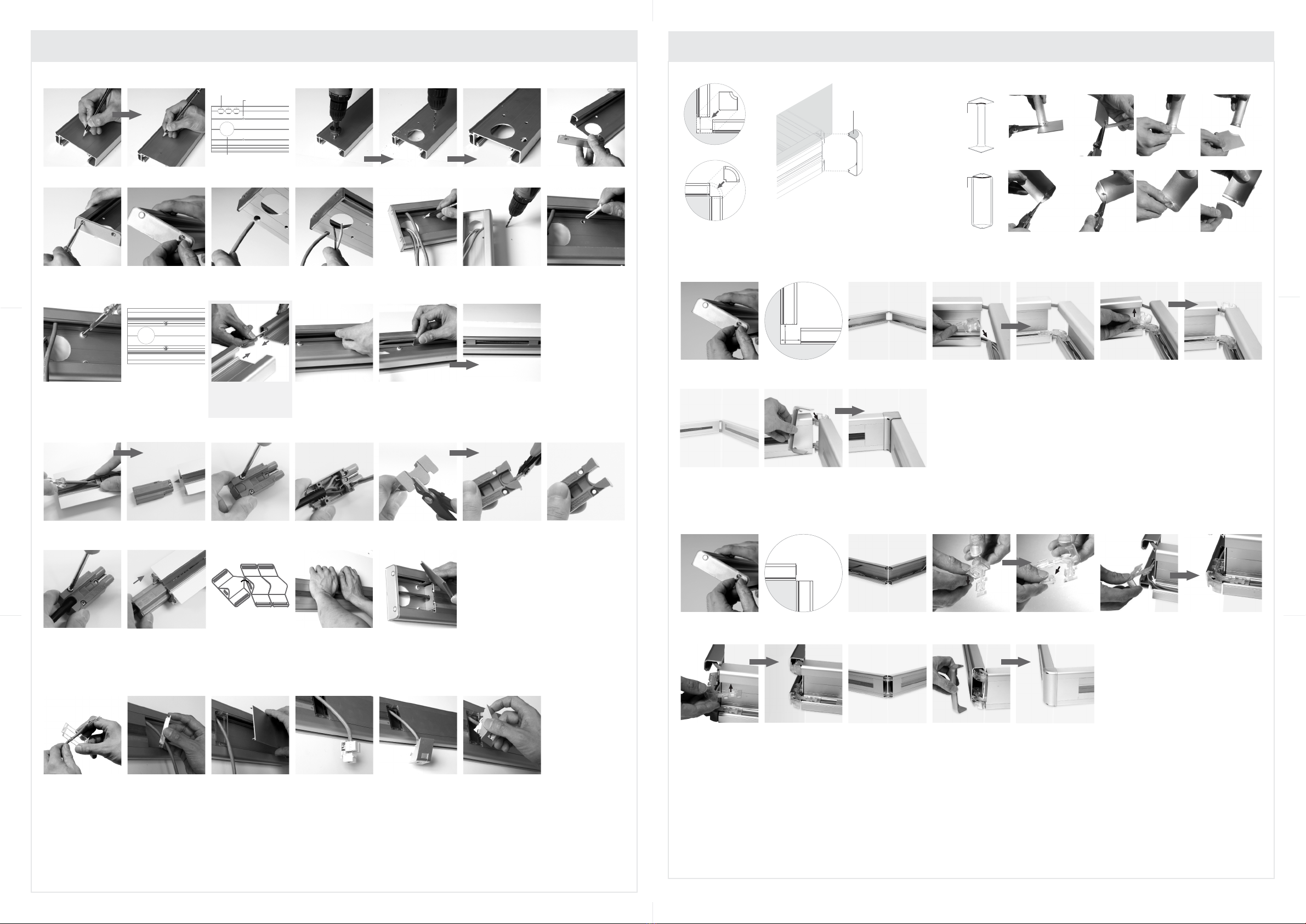
5
CABINET/
OFFICE
FURNITURE
Remove the top cover of the internal/
external corner cap before attaching to
housing. Refer to (a) and (b) on the right
for instructions on removing the top cover.
Top cover to be
removed
6 7
ii
(a) Removing the top cover of internal corner cap
(b) Removing the top cover of external corner cap
iii iv v
ii iii iv v
A. INSTALLING INTERNAL CORNER JOINT
B. INSTALLING EXTERNAL CORNER JOINT
For installation of internal and external corner joints, refer to “Corner Joint Installation”.
3
7
Attach external corner cap to complete installation.
5
6
Attach corner link onto top of housing as shown. * Terminate cables and
install power track, data
housing and blank cover.
4
Break and remove inner latch on corner link as shown. Attach corner link onto bottom of housing as shown.
REMOVAL OF CORNER CAP TOP COVER FOR INSTALLATION OF SH1 UNDER CABINET OR FURNITURE FIXTURE
i
i
Trim Line
Trim Line
INTERNAL CORNER JOINT
EXTERNAL CORNER JOINT
1 2
Follow step 6 to 12 of
“Installation (A)” sequence to
secure and prepare housing.
Follow step 1 to 5 of
“Installation (A)” sequence
to prepare SH1 housing.
Align housing to wall with
reference to “Corner Joint
Guide”.
B. INSTALLING SFC3 MODULAR TRACK SIDE TERMINATION
8 9 10
Wherever necessary, snap
blank cover onto housing.
Snap SFC3 Modular Track
onto housing.
C. INSTALLING DATA POINT
23
Wherever necessary, snap
blank cover onto housing.
Route data cable
through mounting frame.
514
Snap mounting frame
onto housing.
Attach data jack to DS4
data housing with reference
to DS4 User Guide
(DMK-006-010).
Terminate data cable to
data jack.
8
1 2
6
Drill mounting holes on
marked locations.
Align housing to the wall
and insert wall plugs into
drilled holes.
Use the SH1 retainer to secure data cables to the
compartment as shown.
Mark out the positions of cable entry and mounting openings on drill lines provided on the
back of the housing. FIG. A shows the positions of cable entry and mounting openings.
Drill holes at marked locations for cable entry and mounting openings. Use a hole saw
for the power cable entry holes.
Route power and data cables through cable entry
openings and prepare to mount the housing.
4
Using a screwdriver, secure
end cap with screws
provided.
9
Mark out positions of
mounting holes onto the
wall.
7
13
3
Attach end cap to housing.
5
Attach screw caps. Repeat
steps 4 to 6 on opposite
end of housing if corner
joint is not required.
Push data cables into the
data compartment.
12
A. MOUNTING SH1 HOUSING
Snap data housing
onto mounting frame.
6
Installation of Corner Joints
FIG. A
Tighten screws to secure housing onto the wall. FIG. B
shows an example of mounting openings with screws
attached.
10
Data Cable Entry
Power Cable Entry
Mounting Opening
FIG. B
3
8
Follow step 6 to 12 of
“Installation (A)” sequence to
secure and prepare housing.
Attach internal corner cap to complete installation.
5
6 7
* Terminate cables and
install power track, data
housing and blank cover.
4
Attach corner link onto bottom of housing as shown. Attach corner link onto top of housing as shown.Follow step 1 to 5 of
“Installation (A)” sequence
to prepare SH1 housing.
1 2
Align housing to wall with
reference to “Corner Joint
Guide”.
37mm
* For side termination of SFC3 Modular Track, refer to “Installation (B)”
For installation of data points, refer to “Installation (C )”.
8
11
If extension of the housing
length is required, use the
housing joint pin to align
the additional SH1 housing.
Kindly visit our website at www.eubiq.com for product warranty information. ALL RIGHTS RESERVED. EUBIQ AND GSS ARE THE REGISTERED TRADEMARKS OF EUBIQ PTE LTD.
* For side termination of SFC3 Modular Track, refer to
“Installation (B)”
For installation of data points, refer to “Installation (C )”.
37mm
Popular Light Fixture manuals by other brands

Martin
Martin Exterior 1200 Wash user manual

SOLAR VISION
SOLAR VISION LX95 installation manual

Xtralite
Xtralite NiteSafe Duo-Lux instruction manual

Maxxima
Maxxima MRL-61800CNW user manual

California Accent Lighting
California Accent Lighting lipLEDs LLED8350-UC installation instructions

ACME
ACME GEIST BEAM user manual


