manuals.online logo
Brands
  1. Home
  2. •
  3. Brands
  4. •
  5. Maxxima
  6. •
  7. Light Fixture
  8. •
  9. Maxxima MRL-61800CNW User manual

Maxxima MRL-61800CNW User manual

This manual suits for next models

1

Popular Light Fixture manuals by other brands

Veko Magnus manual

Veko

Veko Magnus manual

Cooper Lighting Halo L10538 specification

Cooper Lighting

Cooper Lighting Halo L10538 specification

Emos CLASSIC ZY1431T manual

Emos

Emos CLASSIC ZY1431T manual

Westinghouse Outdoor Lighting Fixture owner's manual

Westinghouse

Westinghouse Outdoor Lighting Fixture owner's manual

Hedler C 12 silent Operation manual

Hedler

Hedler C 12 silent Operation manual

Blizzard Lighting Puck: CSI manual 

Blizzard Lighting

Blizzard Lighting Puck: CSI manual 

Energetic Lighting ELYSL-5004 Series installation instructions

Energetic Lighting

Energetic Lighting ELYSL-5004 Series installation instructions

Lightmaxx Shaft 5R user manual

Lightmaxx

Lightmaxx Shaft 5R user manual

Triarch 31083 Assembly instructions

Triarch

Triarch 31083 Assembly instructions

Philips 32614 Series user manual

Philips

Philips 32614 Series user manual

IKEA TIVED Assembly instructions

IKEA

IKEA TIVED Assembly instructions

Lightolier LP200 specification

Lightolier

Lightolier LP200 specification

Chauvet Professional ROGUE R1 BEAM WASH user manual

Chauvet Professional

Chauvet Professional ROGUE R1 BEAM WASH user manual

Martin MAC 250 Krypton user manual

Martin

Martin MAC 250 Krypton user manual

Cooper Lighting Halo L3232E Specification sheet

Cooper Lighting

Cooper Lighting Halo L3232E Specification sheet

Stageline ODW-2410RGBW instruction manual

Stageline

Stageline ODW-2410RGBW instruction manual

Lightolier Paralyte 2424 PLA2G9LS26U specification

Lightolier

Lightolier Paralyte 2424 PLA2G9LS26U specification

Lightolier Lytespan 83ED17S specification

Lightolier

Lightolier Lytespan 83ED17S specification

manuals.online logo
manuals.online logoBrands
  • About & Mission
  • Contact us
  • Privacy Policy
  • Terms and Conditions

Copyright 2025 Manuals.Online. All Rights Reserved.

6"/8" Commercial LED Retrofit Downlight User Manual
The units covered in these instructions are Type IC, Type Non-IC luminaires.
2. Commercial installation: Service and maintenance of Commercial Downlights should be
performed by a qualified electrician.
WARNING / ATTENTION:
1.
3.
Risk of fire, electric shock or death. If not qualified, do not attempt installation.
SAFETY:
1. For your safety read and understand instructions completely before starting installation.
2.The fixture must be wired in accordance with the National Electric Code and applicable
local codes or ordinances.
Contact a qualified electrician.
Approved Dimmers:
Lutron (0-10V Reqd.): DVDT, NTSTV-DV
www.maxximastyle.com
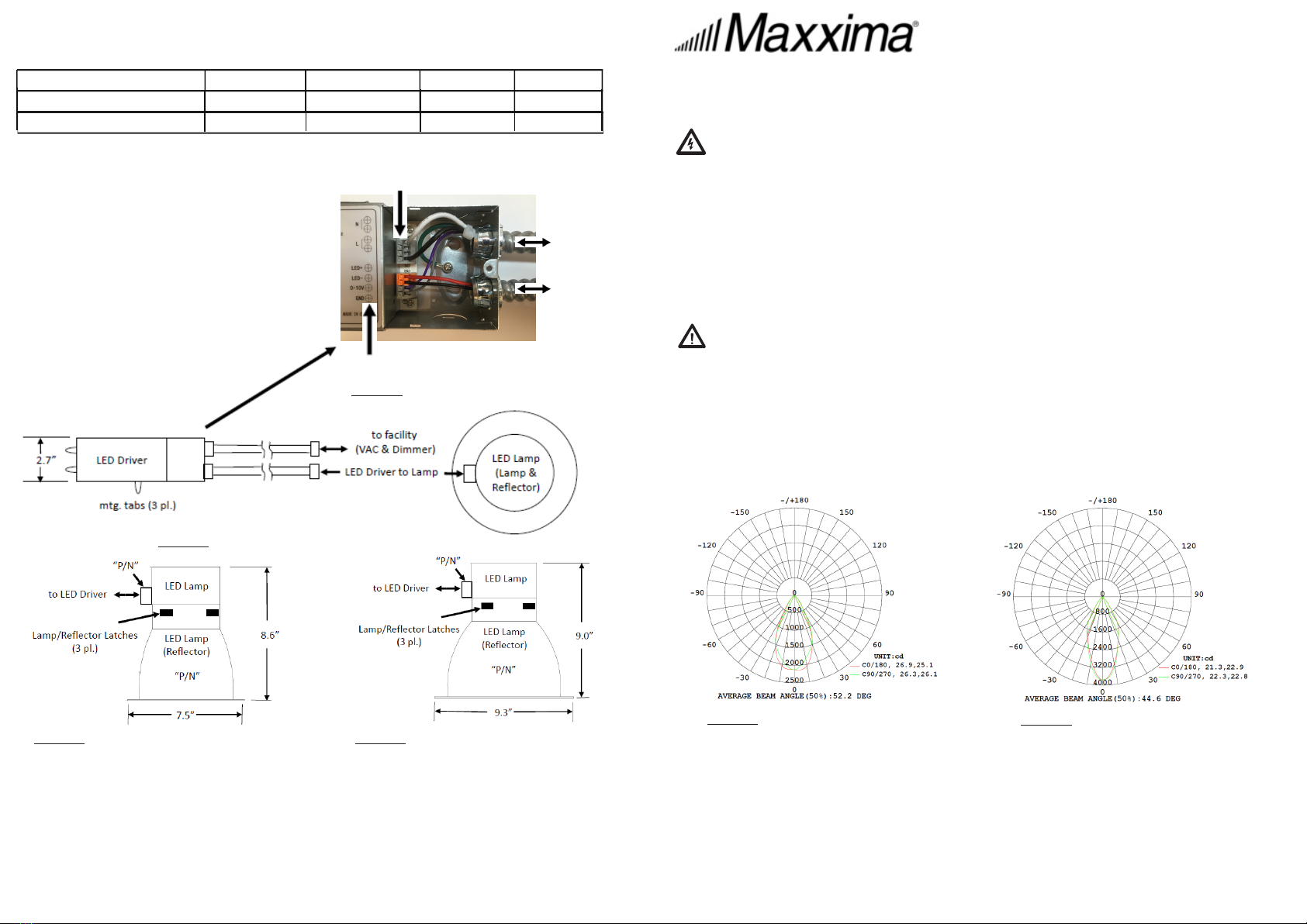
Luminous Intensity Distribution Diagrams:
Residential installation: If you are unsure about the installation or maintenance of the
Commercial Downlight, please consult a qualified electrician for 120 VAC service.
Do not attempt greater than 120VAC installations unless you are a qualified electrician
because severe life threatening electrical shock can occur.
3.To insure personal safety, proper grounding and use of safety cable is required.
Maxxima extends a 5 year limited warranty to the original purchase that the products listed are free from defects in material and/or
workmanship only. Maxxima will replace any warranteed product to the original consumer/purchaser if the product fails because of defects
due to workmanship and/or materials within the limited warranty period.
Limited warranty is not transferable and applies to the original
installation of the Maxxima product. This offer does not constitute in any way a product guarantee and Maxxima does not hereby
assume any obilgation whatsoever beyond sending a free replacement product.
5 Year Warranty:
Figure 1 - MRL-61800CNW LIDD Figure 2 - MRL-82700CNW LIDD
1-866-MAXXIMA
Model Input Voltage (V) Input Frequency (Hz) Input Current (A) Input Watts (W)
MRL-61800CNW 100-277VAC 50/ 60 0.25 18
Electrical Ratings:
1. Install wire: Push gray or orange WIRE
CAPTURE down, insert wire thru hole in plate,
release WIRE CAPTURE.
2. Remove wire: Push gray or orange
WIRE CAPTURE down, remove wire, r
elease WIRE CAPTURE.
4 each WIRE CAPTURES per Terminal Block
to LED Lamp
to Facility
(VAC/dimmer)
Dimensions & Compatibility:
IMPORTANT INSTALLATION NOTE: P/N on LED Driver must match P/N on LED Lamp!
INSTALLATION NOTE: Reflector may be separated and reattached to LED Lamp by 3 latches.
MRL-61800CNW - Recessed LED Lamp with Reflector: 7.5" (DIA) X 8.6" (H) (fits 6" to 6.7" opening)
MRL-82700CNW - Recessed LED Lamp with Reflector: 9.3" (DIA) X 9.0" (H) (fits 7.7" to 8.4" fopening)
LED Driver (P/N MUST match LED Lamp): 7.1" L x 2.7" W x 1.4" D (plus (qty. 3) mounting tabs)
Whips (LED Driver - Flexible Metal Conduits): 1/2" x 14" length each (with snap-tite connectors)
Wiring labeled on LED Driver
Figure 3 - LED Driver (pre-wired as shown)
Figure 4 - LED Driver & LED Lamp (top view)
MRL-82700CNW 100-277VAC 50/ 60 0.35 27
LED Driver - Terminal Block Use (comes pre-wired):
Figure 5 - 6" MRL-61800CNW LED Lamp Figure 6 - 8" MRL-82700CNW LED Lamp
STEP1: Turn OFF the power before starting installation.
STEP3: Locate and secure LED Driver in ceiling where Facility Whip will reach J-Box for
100-277VAC 50/60Hz power and 0-10V dimmer wires (if applicable) and LED Lamp Whip will
reach to plug into LED Lamp & Reflector assembly and maintain slack when lamp is pushed
completely into Ceiling Ring. LED Drivers come with 14" length Whips.
STEP4: Use (qty 5) wire nuts provided to connect power, ground & dimmer control to
facility J-Box.
STEP5: Insert (qty 3) clips provided onto ceiling ring roughly evenly spaced (see Figure 8).
STEP8: Plug LED Lamp Whip connector into LED Lamp.
Installation Instructions:
IMPORTANT! Read all WARNINGS & SAFETY NOTES on other side.
Figure 7 - LED Driver & LED Lamp (Top view & Side view 6" LED Lamp shown)
STEP9 (optional function check): Turn on power and do functional test of lamp and
dimming.
STEP10 (optional function check): Turn off power for final installation.
STEP6: Loop Safety Cable to secure lamp as required by code. As shown in Figure 9, push in
small end of Cable Lock to release cable to expand loop or remove cable from Cable Lock if
needed. Once looped around supporting structure, push safety cable into Cable Lock if needed
to tighten cable loop.
STEP11: Push LED Lamp & Reflector in ceiling opening until trim is flush with ceiling and
make certain that ceiling ring can support full weight of LED Lamp & Reflector.
STEP12 (Final Functional Test): Turn on power and do functional test of lamp and
dimming.
6"/8" Commercial LED Retrofit Downlight User Manual
www.maxximastyle.com
1-866-MAXXIMA
Figure 8 - Ceiling ring clips (qty. 3) positioning and close-up.
STEP2: Remove and discard existing reflector. Locate supply power and/or ballast to
dismantle and remove ballast as needed and prepare supply power leads in local J-Box for
connection to LED Driver in STEP5. Cap off supply power leads temporarily for safety.
STEP7: Do final check to secure wiring & close J-Boxes, etc.
Figure 9 - Cable Lock - Adjustments
1. LED Lamp (Lamp & Reflector with Safety Cable attached)
2. LED Driver (with 2 Whips pre-wired)
3. (Qty. 5) Twist-on wire nuts connectors
4. (Qty 3) Black Ceiling Ring Clips
Contents (per Downlight)