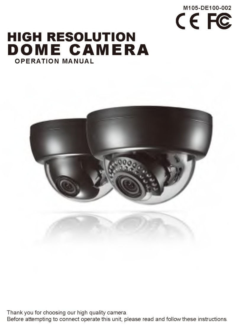
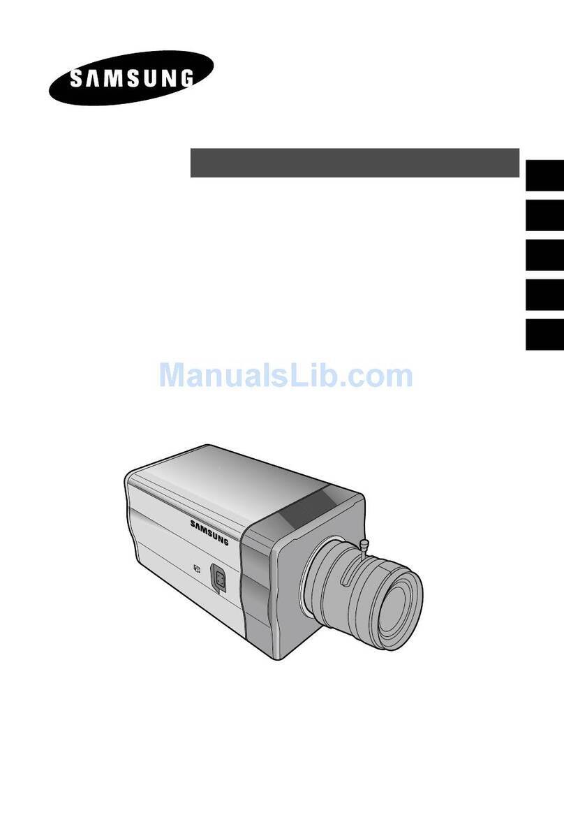
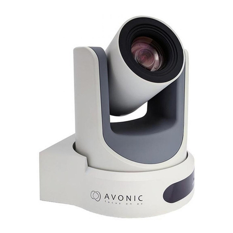
EURA CEA-41C5 User manual

CEA-41C5
High-Denition
PTZ Network Camera
User Manual

2
Table of contents
1. Device characteristic ............................................................................................................. 4
2. Device construction...............................................................................................................5
2.1. Installation method.........................................................................................................5
3. Device conguration ............................................................................................................ 6
3.1. Connection device .......................................................................................................... 6
3.2. Typical wiring diagram...................................................................................................7
3.3. Using Admin Tool congure the camera’s IP Address............................................. 8
4. Access to the device.............................................................................................................. 9
4.1. Access using WEB Browsers......................................................................................... 9
4.1.1. Logon....................................................................................................................... 9
4.1.2. Video plugin ........................................................................................................ 10
4.1.3. WEB Browser Interface ..................................................................................... 10
4.1.4. Connection, Snapshot and Recording............................................................. 11
4.1.5. Video Specication Adjustment.......................................................................12
4.1.6. PTZ Control...........................................................................................................12
4.1.7. Image Modes ........................................................................................................15
4.1.8. Video Replay ........................................................................................................16
4.1.9. Video Stream Parameter....................................................................................17
4.1.10. OSD.......................................................................................................................18
4.1.11. Motion Detection ...............................................................................................19
4.1.12. Advanced Functions.........................................................................................20
4.1.13. Device information........................................................................................... 23
4.1.14. Privacy mask...................................................................................................... 23
4.2. Access using RTPS Player........................................................................................... 24
4.3. Access using NVR......................................................................................................... 24
4.4. Access using Video Management Soware ........................................................... 25
5. Parameter Setting............................................................................................................... 25
5.1. Channel Parameter....................................................................................................... 26
5.1.1. Audio Parameter Setting itd. ............................................................................26
5.1.2. RS485 Parameters.............................................................................................. 26
5.1.3. Automatic cruise protection..............................................................................27
5.2. Network Parameters....................................................................................................27
5.2.1. Network Settings ................................................................................................27
5.2.2. RTPS Parameters ............................................................................................... 29

3
5.2.3. NTP Parameters ................................................................................................. 29
5.2.4. Heartbeat Setting..............................................................................................29
5.3. Recording Parameters ................................................................................................30
5.3.1. FTP Parameters...................................................................................................30
5.3.2. Snapshot Parameters ........................................................................................31
5.4. Alarm Settings...............................................................................................................31
5.4.1. Alarm Input...........................................................................................................31
5.4.2. Alarm Output...................................................................................................... 32
5.5. System Parameters ......................................................................................................33
5.5.1. User Management ...............................................................................................33
5.5.2. Advanced System Maintenance.......................................................................35
5.5.2.1. System Time ......................................................................................................35
5.5.2.2. Upgrading Soware Via WEB .......................................................................35
5.5.2.3. Saving Setting ................................................................................................. 36
5.5.2.4. Restoring Factory Defaults ...........................................................................37
5.5.2.5. Restart ...............................................................................................................37
5.5.2.6. Device Expanded Parameter.........................................................................37
5.6. Log view..........................................................................................................................37
5.7. Additional parameters..................................................................................................37
6. Technical parameters ......................................................................................................... 38

4
1. Device characteristic
Thanks for using our HD network Camera which is based on the standard H.264 Main Prole. It uses the
progressive scanning image transducer of mega pixels and its denition can meet the broadcast image quality. It
supports real-time dual-stream coding and its recording les can be decoded by standard decoders and played
by common player soware. The device doubles the quality of MPEG-4 with the same bit rate. To achieve the
same image quality, the bit rate is only half of that of MPEG-4. The product is easy to be operated and installed,
and can signicantly reduce the cost of wiring and construction and extend your CCTV network innitely.
Product Features:
•HDTV HD Vision
− HDTV performance, that supports full HD 1080P + Full D1 or SXGA + Full D1 dual-stream resolution, 16:9
aspect ratio and supports H.264 main prole in full frame rate.
•Zoom & AF
− Optical zoom and auto focus function, that not only can deliver best view distance but also can realizes
perfect auto focus.
•Low Code Stream + High Denition
− Perfect low code stream function, the video denition can reach to 720TVL when compress 720P video under
2~4Mbps,
− When compress 1.3MP video under 3~5Mbps, the video denition can reach to 800TVL,
− The video denition can reach to 1000TVL when compress 1080P video under 4~6Mbps.
•Stronger Intelligent Function
− Support WEB access to visit and congure the devices, support OSD, support real time video transmission,
support motion detection,
− Built in network code function, support ONVIF protocol,
− Support JPEG capture picture,unied client remote control monitoring soware and easy connect the brand
NVR,
− Ethernet 10/100 RJ45 auto adaptive, support RTSP/FTP/PPPOE/DHCP/DDNS/NTPS and so on network
protocol.
•PTZ Control
− Pan 360°, continuous rotation; Tilt 90°, no monitoring blind spot,
− Auto adjust PTZ speed according to the zoom function.
•Night vision
− Auto open infrared lamps according to the light,
− Auto adjust the brightness of infrared lamps based on the lens far or near.
− Adopt the forth infrared array light technology coordinate with intelligent dimming technology, better night
vision.
− Suitable for HD network monitoring occasions needing zoom control:
− Safe city large and medium concentration application, expressway, road and bridge, tunnel trac real-time
monitoring
−HD video conference
− Real-time night HD monitoring for nancial organizations, like banks
− 24-hour security monitoring HD network for factories and stadium
− Real-time remote monitoring for airport, school, plaza, etc.
− HD environment monitoring for forest and scenic region, etc.
−HD digital court monitoring application.

5
2. Device construction
Fig. 1. Dome Camera
2.1. Installation method
’L’ type speed dome camera installation method
Step 1- Draw positioning holes
Take out bracket from package box, mark the hole’s position on wall or ceiling based on mount bracket bottom
4pcs installation holes.
Step 2- Drill holes and put expansion screws in
Drill 4pcs expansion screw’s installation holes at pre-marked position, then put 4pcs expansion screws in.
Note: Please bring expansion screws own.
Fig. 2. Step 3
Step 3 - Lead cable through wall mount bracket
Lead the cable through wall mount bracket hole.
Fig. 3. Step 4

6
Step 4 - Connect speed dome camera and wall bracket.
Put speed dome camera connection port into the bracket hole and screw 4pcs hexagon screws into the corre-
sponding screw holes.
Fig. 4. Step 5
Step 5 - Fix the speed dome camera
Lead the cable out from the wiring port, then x it on the wall by using 4 screws. Seal the wiring port of the brac-
ket by using silicon sealant.
Step 6 - Cable connection
Please refer to section of six of this chapter- Connection method.
Step 7- Tear o protection lm
Tear o protection lm of transparent cover
Note: Please take care of the transparent cover.
3. Device conguration
3.1. Connection device
Connection method as below program, order to connect network cable, power supply cable(connect order based
on the keyboard model number, here just give one example). Details as below:
Fig. 5.

7
3.2. Typical wiring diagram
LAN Connection
Fig. 6.
WAN Connection
Fig. 7.

8
3.3. Using Admin Tool congure the camera’s IP Address
The system provides the management test tool – Admin Tool. Please check the system CD. The tool can:
1) Search network cameras or video servers in the network.
2) View serial number, name, IP, version, product model, port, and MAC address, etc.
3) Assign and setup IP and specify a management center in batch.
4) The status indicator can conrm the current network camera for restart and upgrade, etc.
Fig. 8.
Congure the IP address of the specied camera
Running the Admin Tool management tools automatically retrieve network camera device available in the
current network. Lists the MAC Address, IP Address, device name and other information; select a device and
double-click, the device information dialog box pops up, you can congure the device name, IP address, default
gate and other information.
Fig. 9.

9
Batch congure the IP address of the network camera
The Admin Tool management tools can use the same IP address each camera factory before being installed
in bulk conguration of multiple network cameras IP address.
These network cameras are connected to the same switch with the machine, through the Admin Tool quick
search network of devices, the mouse marquee multiple camera equipment, click the “batch Conguration”
button, the batch IP address conguration window pop-up. The user can set the starting IP address and ending
IP address and other content, bulk assign IP addresses to these network cameras, specify the subnet mask,
default gateway, port and center IP information. Meanwhile, we can use the tool to open the status indicator to
conrm which network camera is being tested, easy for putting on a label aer testing.
Fig. 10.
4. Access to the device
4.1. Access using WEB Browsers
4.1.1. Logon
Fill in the IP address of the network camera into the URL of your WEB browser. The default IP is 192.168.1.4.
The logon dialog box is shown as below.
Fig. 11.
Username: The default username of the network camera is system.
Password: The default password of the network camera is system.
Port: The data port of the network camera is default to be 6002.

10
Note:
1) If the data port of the network camera is changed, please ll in the changed port when logging on. Or it is
not allowed to log on.
2) Please click the push-down list at the upper right corner of the logon interface to change the language.
4.1.2. Video plugin
First-time logon and installation:
Aer logging on successfully, the user is prompted to download the play plug-in if it is the rst time for the
device to access. Please download and run the play plug-in installation manually. The name of the play plug-in
is HDLive.exe.
Fig. 12.
Double-click the downloaded HDLive.exe. The le shall automatically start its installation of play plug-in for
HD Network Camera User’s Manual WEB browser. Conrm your installation by clicking “Next Step” till the completion
of the installation. Aer the completion of the installation, return to the WEB browser page and refresh the page
to browse the video.
Updating plug-in
When detecting new version of the play plug-in, the system shall prompt updating new version of play
plug-in.
Fig. 13.
Note:
It is required to install this play plug-in if using WEB to browse the video. Currently the plug-in supports
Windows XP/2003/7/8/8.1/10 32 and 64 bits OS.
Due to the reason that the security setting of IE browsers is dierent, it may be required to allow the
uploading of the play plug-in. Please click “Allow” button when the following prompt is shown.
Fig. 14.
Some browsers may be required to congure “Internet options – Security – Custom level”. In the security
settings, please set the ActiveX component and plug-in to be “Enable” or “Prompt”.
Display Resolution
WEB browse client interface optimum display resolution is 1024x768, below this resolution it may cause
incomplete or dislocation and pop up warning prompt window.
4.1.3. WEB Browser Interface
Please refresh the video browse page aer installing the play plug-in. It is divided into three sections shown
as below.
Top: Login user information, detailed settings and exit.
Lower le: Video display
Lower right: Common parameter adjustment and control. Click labels to switch and congure.

11
Note:
There is always delay when transferring video via network. The delay has relation to the processing
capability of user computer as well as the number of switches and routers that are passed by. In general
circumstance, it is normal for mega pixel HD network video to have the delay within 500ms.
Fig. 15.
It is able to download components again by using the button “Update video component” on the top of the
video display. It is required to close the browser interface during the installation. The status information of the
video connection shall be displayed on the upper le of the video, like IP address, connection status, denition
and frame rate shown as below.
Fig. 16. Fig. 17.
In the video display, the information like camera name, date and time, can be concatenated. Please refer to
the section 5.1 for settings. It is shown above.
4.1.4. Connection, Snapshot and Recording
If the play plug-in is installed with no mistake, the video browse page shall automatically connect the
network camera’s main stream. The buttons at the bottom of the video area are shown as:
Fig. 18.
: Click this button to connect the image of the network camera via the set parameters of the Stream 1
(main stream). It is default to connect automatically.
: Click this button to connect the image of the network camera via the set parameters of the Stream 2
(slave stream). Some models may not support this.
: Click this button to disconnect the currently connected image of the network camera.
: Click this button to capture the image snapshots currently browsed, save to the default directory.
: Click “Video recording” button to pop up “Save as” dialog box. It is able to start the video recording
manually and select the local storage path. While clicking “Video recording” button, the camera is starting
to record video. Please ll in the le name in the popped up dialog box. The status of “Video is recording” is
prompted at the bottom of the video display area. Now the button is changed to “Stop video recording”. Click
“Stop video recording” button to end the recording and save it into the local path.
: This button can open or close real-time audio monitoring.

12
4.1.5. Video Specication Adjustment
Click “Video adjustment” label at the right of the video browsing window to adjust the information
including video brightness, contrast, saturation and color. Please click “Set” button to save the adjustment aer
completing the adjustment. The video parameters have been optimized when delivered from the factory. The
default values are:
Brightness: 120 Contrast: 75 Saturation: 70 Color: 128 Sharpness: 127
Sharpness
Sharpness is also called “denition” sometimes. It is an index that reects the image denition and the
sharpness of the image edge. Its default value is between 80 - 100. When the value of sharpness is too large, the
image may have many noises appeared. When it is too small, the image denition may be aected.
Fig. 19.
Types of video transmission
Use a slide bar to adjust the buer time for video image so as to make the video connection more real-time
or smoother. The “Real-time” on the le has the 0ms buer time (No buer). The “Smooth” on the right has the
buer time of 5000ms. Users can adjust by themselves according to the user-end host conguration and the
network bandwidth. The default is set to be real-time connection and the buer time is about 300ms.
4.1.6. PTZ Control
Click the “PTZ” label at the right of the video browsing window to control the PTZ.
Fig. 20. Fig. 21.

13
PTZ speed
The PTZ rotation rate is adjustable between 1 to 255. Dierent PTZs have dierent rate. The corresponding
value is slightly dierent. Please refer to PTZ specication.
UP, DOWN, LEFT AND RIGHT KEY
The keys are used for controlling the movement of the PTZ orientation.
PTZ Automatic Rotation
Aer being pressed down, the PTZ can automatically rotate horizontally. The function needs the support of
the PTZ.
ZOOM!IRIS! FOCUS
These control rooming, iris and focus of the camera lens, used for electrical zoom lens and integral control.
3D Positioning Control
Enable the 3D positioning control function to use the le mouse key to click or select any area to operate,
like moving the area to the center of the image preview, automatic zooming (within the valid zoom range of the
automatic zoom lens), and automatically rotating the PTZ to its current position (It requires the support of PTZ.)
Mouse click: The view shis to one centering on the currently clicked point.
The mouse can select from the upper le to lower right. The view shis to one centering on the currently
selected area. The lens automatically zooms in the currently selected area.
Mouse selects from the lower right to the upper le. The view shis to one centering on the currently
selected area. The lens automatically zooms out the currently selected area.
Aux Switch
It supports turning on/o of the PTZ’S windscreen wiper, fan (heat dispersion), spot light, and heating.
Focus modes
Manual and auto. It is able to set the focus modes of the zoom lens to be manual focus or auto focus. Under
the mode of manual focus mode, the lens focal distance is always locked without any change.
Preset point
1 – 256. It records the PTZ’s current position and lens zoom. The operations like addition, edition, calling and
deletion, etc., can be carried out. The preset point supported by dierent PTZ’s may be slightly dierent.
Save the preset point: remove the PTZ to a certain position, the lens to adjust to the corresponding multiples,
click on “save” button to point to save the current position to a preset. Saved preset point number will be orange.
Call the preset point: school ocial cites use the mouse to click on the saved presets, PTZ set automatic steering
has the preset point location; If the lens had three variable changes will also be a synchronous invocation.
Deleting preset point: school ocial cites use the mouse to click on the preset point, select the “delete” button.
Edit the preset point: click on the “edit” button, preset point edit window will pop up, the user can add, delete, modify the
preset point preset a name, and so on. Preset a name cannot be more than 32 characters.
Fig. 22.
Click on the „advanced” button, you can set the guards, preset cruise and fancy scanning, and other
functions.

14
Preset Group (preset points grouping)
8 patrol groups. Each group has 16 pre-set points. Select any number of pre-set points and specify the stop
time of each point. The PTZ can patrol these points automatically. The number of the PTZ that can be set by a
patrol group depends on the PTZ.
Fig. 23.
Note:
Here set the preset a cruise marshalling support only call manually. If need regular automatic call, please
refer to the manual section 5.1.3.
Mode path (Pattern, track)
8 paths to record the PTZ’s whole running path and the lens zooming. The track number and record time
that can be saved by dierent PTZs are also dierent.
Fig. 24.
Operation: Click to add “start recording”, then rotate the PTZ or control the lens zooming, and click stop
when completed. The system shall record the whole process of the operation and save it as a path of scan track.
Click the recorded track to call or delete.
Guard (also called watch function or Home)
The default is over 30s. If the PTZ receives no operation instruction (idle) in a specied time period, the PTZ
shall automatically call (return) the pre-set point.
Fig. 25.

15
Operation: Enable the keep watch function to set the idle time and the number of the called preset point
and save them, the longest idle waiting time can be set to 99999 seconds, but should not be commonly set is
too long.
Note:
1) all PTZ control functions need to camera RS485 ports baud rate, the agreement, address and other
information set to the same as the PTZ decoder board Settings can be controlled, please refer to this manual
4.1.2 RS485 parameter Settings;
2) to avoid parameter is missing, please set all the parameters in and then click the “save Settings” button in the
top right corner interface, to save the parameters.
4.1.7. Image Modes
Fig. 26.
Click “Image mode” label at the right to set up the video parameters under certain circumstances (E.g.
daylight, strong light, and night light, etc.) These modes can set up dierent start time and stop time, and can
automatically adjust to match the latitude and longitude of where the camera is installed.
Image mode setting: Daytime mode, strong light mode, dawn mode and night mode. Each mode can set to
be a corresponding time range. Each mode can set up dierent video parameters according to the current
circumstance so as to reach the best image eect.
Longitude and latitude setting: If enabling the image mode, the system shall provide the longitude and
latitude setting of the device installation position. Aer setting up the longitude and latitude of the device
installation as well as the initial start time and stop time of the image mode, the system shall automatically
calculate the start and stop time of the image mode every day based on the longitude and latitude.
Note:
In the time-phased setting, if the start time of two modes overlaps, the mode gets started according to the
order of the modes, subject to the last mode. If the parameters above are modied, please go to the page of
Advanced settings” to click “Save settings” button. Otherwise, all the modied parameters shall be lost aer the
power is disconnected. Please refer to “Saving settings”.

16
4.1.8. Video Replay
Click “Playback” label in the right of the video display area to switch to the record le play windows to play
the local record les and those on the SD card of the network camera.
Fig. 27.
If there is a SD card in the camera, it is able to click “Search” button to search the records on the SD card
according to date and channel. The “Select local les” button can be used to select the local manually recorded
or backup les and list below. Double click a le to replay it. While replaying, the operations like fast play,
snapshot and opening audio, can also be carried out. When the record is paused, click “Next frame” to browse
the image in each frame.
As for the record les or pictures searched remotely, select a le and right click the mouse to download it to
the local computer.
“Search”: It is used for searching the record les on the SD card of the network camera.
“Select local les”: Retrieve and select the record les manually recorded or backup for play.
“Play/Pause”: Play or replay the currently-selected record le. Press “Next frame” to play the next frame while
pausing.
“Stop”: Stop playing.
“Fast Forward X2”: Play fast forward by doubling the speed.
“Fast Forward X4”: Play fast forward by 4 times of the speed.
“Snapshot”: Capture the snapshot of the record video that is played.
“Open audio/Stop audio”: Open audio while replaying. Click “Stop audio” if mute is acquired.
“Return”: Return to the replay window. It is able to browse the interface in real-time.

17
4.1.9. Video Stream Parameter
Select “Stream” label at the right of the video display area to set up the parameters like video denition rate,
and the size of stream, etc. Users can select the video stream type built in the system as well as select the
combination of multi-bit stream types. The default stream 0 is the main stream and the stream 1 is the slave
stream. The stream 2 can be CVBS analog output or HDMI HD digital output.
Fig. 28.
Video Stream types: The video coding types built-in the system include dual-stream, triple-stream,
dual-stream + CVBS analog output, and dual-stream HDMI HD digital output, etc. If it is required to be tested
via CVBS(That is, BNC interface), please select the video code type with CVBS output. For dierent video camera
models, the highest denition combination supported by main stream is dierent. Please refer to Appendix D.
D1 Format Selection: Image resolution supports 720*576 or 704*576, and user can select according
application, 720*576 defaulted.
Stream Encryption Way: support “standard data stream” or “encryption data stream”, and user can select
according practical application requirements. When selecting “standard data stream”, back-end video can be
played by general player; while selecting “encryption data stream”, back-end video can only be played by special
player.
Frame rate: There are many types of frame rate. Full frame rate represents the real-time level with the
highest of 25 frames (PAL mode) or 30 frames (NTSC mode), and the 1/10 level with the lowest of 2 frames (PAL
mode) or 3 frames (NTSC mode).
Coding types: There are two options: video stream and composite stream. The video stream contains no
audio. However, the composite stream includes video and audio.
Bit rate mode: It includes two types: xed bit rate and limited bit rate. Users can select the size of the bit
rate, and also can self-dene the upper bound of the bit rate.
Image quality: It sets up 6 grades from normal to the best. Normally if the image quality is prior without
considering the bandwidth occupation, it can set up to be the best; if the image quality and the bandwidth (bit
rate) are both under consideration, it can set up to be better or even better.
Bit rate upper bound: 32Kbps~2048Kbps. User can self-dene the higher bit rate.
Custom bit rate: When the bit rate type is limited bit rate, users can self-dene the upper bound of the bit
rate. For Full HD (1920x1080P), the bit rate is recommended to be 4~6Mbps (4096~6144Kbps); for
HD(1280x720) to be 2~4Mbps (2048~4096Kbps); and for Full D1(720x576) or 960H (960x576) to be 1~
3Mbps (1024~3072Kbps). The highest bit rate can be 8Mbps. The set bit rate cannot exceed the highest upper
bound of the bit rate under each individual denition.

18
Note:
1) Compression format: The main stream is default to use H.264 compression format. The slave stream can
select H.264 and MJPEG. When the slave stream is H.264 compression format, the highest denition supported
is Full D1(720x576); when the slave stream is in MJPEG compression format, the highest denition supported is
HD(1280x720). The slave stream in MJPEG compression format is commonly used for the camera to capture
images with higher denition.
2) It is required to save parameters in “Detailed settings -> System parameters -> Advanced settings” and
restart settings aer the video stream type is modied.
3) Three mega-pixel and ve mega-pixel cameras only have Stream 0 when it is in its highest denition.
4.1.10. OSD
Select “OSD” label at the right to overlap the information of videos, like channel name, week, and time etc.
Fig. 29.
Item Application
Channel name Set up channel names to overlap on the video images. It supports 63 English
characters. The characters exceeding the limit shall be automatically truncated.
It is able to insert \n to change lines.
Overlap
setting Upper le corner, lower le corner, upper right corner, lower right corner.
Coordinate 0~576, Origin of coordinates relative points for choosing.
Overlap channel name, overlapping week and date and time are optional for users.
Overlap channel name: The position can be relative to the upper le, lower le, upper right, lower right of a
video. The coordinate can be any relative positions between 0 – 576.
Overlap time can choose a long complete date: year month day weekday hour minute second; or a short
date: year month day or hour minute second.
Display week: English for the rst three letter abbreviation, like WED.
Expanded title: Show some extra text note information, like street, telephone number, contact person, etc.
It supports 120 English characters.

19
4.1.11. Motion Detection
Select “VMD” label on the right for users to start the camera’s video motion detection. If the camera is
installed at the places like corridor, door or windows, the image pictures are normally static relatively. Once the
camera detects any object in movement in the video, it shall start recording or generate alarm linkage or output.
The video area on the le is the video motion detection area. Users can use their mouse to draw up at most
ve areas in the video area to be the targeted motion detection areas. When detecting any element in motion in
the video, the corresponding associated alarm linkage shall be triggered. If it is required to redraw the areas for
detection, users can click “Clear areas” button on the right.
Fig. 30.
On the right are the settings for the motion detection for defending and the alarm linkage.
Motion threshold: The default value is 1 (The range of the value is 0 - 100). The motion threshold value is
for measuring the ratio of objects in motion in the selected areas. Smaller the value is, smaller the ratio of
objects in motion is.
Sensitivity: The default value is 3 (The range of the value is 0-5). The sensitivity is used for evaluating the
level of sensitivity of motion detection. Larger the value is, higher the sensitivity is. Even small motions can be
detected.
Note:
A very low sensitivity may cause failure to report (No alarm when there is any object in motion in the video).
A very high sensitivity may cause false alarms (Any subtle motion like leaf or mice may trigger alarm.) The motion
threshold and sensitivity need to be adjusted in an actual application according to user environment. If the values
cannot be ensured, please keep the default values or increase the sensitivity.
Fig. 31.

20
The time phase for motion detection can be set based on requirements. Users can set up four time phases,
and also can copy the set time phases to the areas where the same time phase is set for defending. Meanwhile,
the process methods are also selectable when any objects in motion are detected. The process methods for
alarm include uploading to the management center, linking the PTZ preset point, linking the scan track, preset
points patrolling, snapshot, recording or triggering the camera’s Relay outlet, etc., as shown in the gure below:
Fig. 32.
4.1.12. Advanced Functions
Click “Advanced functions” label on the right to set up color mode, white balance, wide dynamic mode and
noise reduction modes, etc.
Fig. 33.
Anti-ickering mode: Two modes - 50HZ and 60 Hz which can be set based on local power frequency.
Color mode: Two modes – PC and TV. Choose PC mode when connecting a PC monitor and choose TV mode
when connecting a TV monitor.
White balance: The basic idea of white balance is that “Return a white object into white no matter under
any kind of light source”. The color oset appearing under certain light source can be compensated by enforcing
the corresponding complementary color so as to make the camera images restore their original images under
various color temperature as much as possible. Normally we represent the dierent color hue under dierent
light conditions to be dierent color temperature. It defaults to be automatic. When choosing auto, images are
automatically adjusted by the camera’s 3A system. The system has other modes built-in: incandescent lamp,
D4000, D5000, daylight, cloudy day, ash light, uorescent lamp, uorescent lamp H, and underwater, etc.
Table of contents
