7
INTRODUZIONE
Gentile cliente,
vogliamo anzitutto ringraziarla per la preferenza accordata ai
nostri prodotti e ci auguriamo che l’uso di questa macchina
le riservi grandi soddisfazioni e risponda appieno alle sue
aspettative.
Questo manuale è stato redatto per consentirle di conoscere
bene la sua macchina e di usarla in condizioni di sicurezza ed
efcienza. Non dimentichi che esso è parte integrante della
macchina stessa, lo tenga a portata di mano per consultarlo
in ogni momento e lo consegni assieme alla macchina il
giorno in cui dovesse cederla o prestarla ad altri.
Questa sua nuova macchina è stata progettata e costruita
secondo le normative vigenti, risulta sicura ed afdabile se
usata nel pieno rispetto delle indicazioni contenute in questo
manuale. Qualsiasi altro impiego o l’inosservanza delle
norme di sicurezza d’uso, di manutenzione e riparazione
indicate è considerato come “uso improprio” e comporta il
decadimento della garanzia e il declino di ogni responsabilità
del costruttore, riversando sull’utilizzatore gli oneri derivanti
da danni o lesioni proprie o a terzi.
Nel caso dovesse riscontrare qualche leggera differenza fra
quanto qui descritto e la macchina in suo possesso, tenga
presente che, dato il continuo miglioramento del prodotto, le
informazioni contenute in questo manuale sono soggette a
modiche senza preavviso o obbligo di aggiornamento; fermo
restando le caratteristiche essenziali ai ni della sicurezza e
del funzionamento. In caso di dubbio contatti il suo rivenditore.
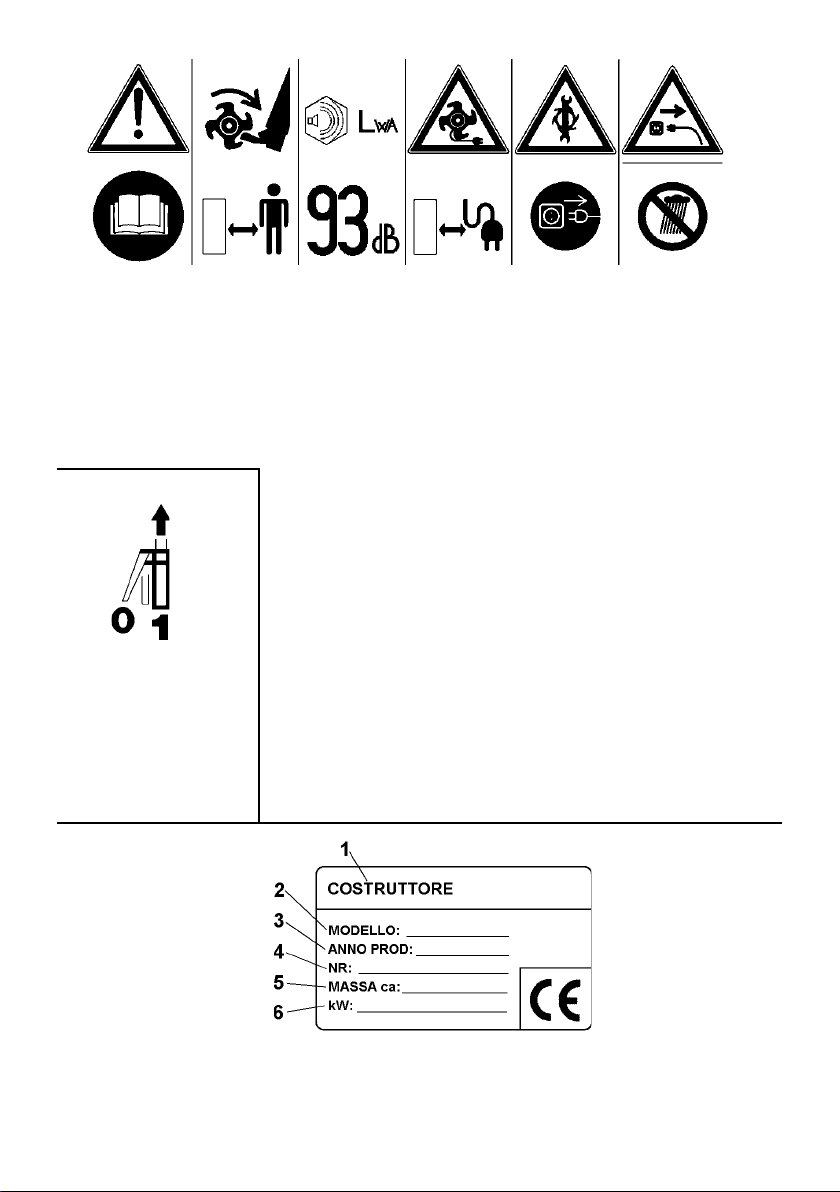
DATI PER L’IDENTIFICAZIONE (Fig. 1)
L’etichetta (C) con i dati della macchina e il numero di matricola
è incollata sulla parte posteriore destra del telaio. Nota: Nelle
eventuali richieste di assistenza tecnica e nelle ordinazioni delle parti di ricambio, citare sempre il
numero di matricola della motospazzola interessata.
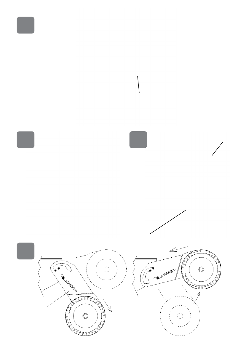
CONDIZIONI DI UTILIZZAZIONE – LIMITI D’USO
La motospazzola è progettata e costruita per eseguire operazioni di manutenzione di prati in erba
sintetica. Con la sua spazzola, rotante nel senso di marcia, solleva il lo di erba sintetica e livella
il fondo del campo. Ogni utilizzo diverso da quello sopra descritto è illegale; comporta oltre al
decadimento della garanzia, anche un grave pericolo per l’operatore e per le persone esposte.
NORME DI SICUREZZA
Sulla macchina ed all’interno di questo libretto, sono presenti scritte ed indicazioni
accompagnate da questo segnale, che stanno ad indicare la presenza di un
potenziale pericolo. E’ opportuno utilizzare una particolare prudenza per la propria
sicurezza e di quanti si possono trovare nel raggio di azione della macchina.
ATTENZIONE: prima del montaggio e la messa in funzione leggere attentamente il libretto istruzione.
Le persone che non conoscono le norme di utilizzazione non possono usare la macchina.
1. L’ uso della macchine è vietato ai minori di 16 anni e alle persone che hanno assunto
alcol, medicine o droghe.
2. Controllare che i bambini e gli estranei stiano lontani. Siete responsabili dei danni
causati a terzi.
3. Utilizzare la motospazzola solo in condizioni di buona visibilità ed illuminazione ( naturale
od articiale). La visibilità è fondamentale per garantire una situazione di sicurezza.
Indice
Introduzione
Dati per l’identicazione
Condizioni di utilizzazioni
Norme di sicurezza
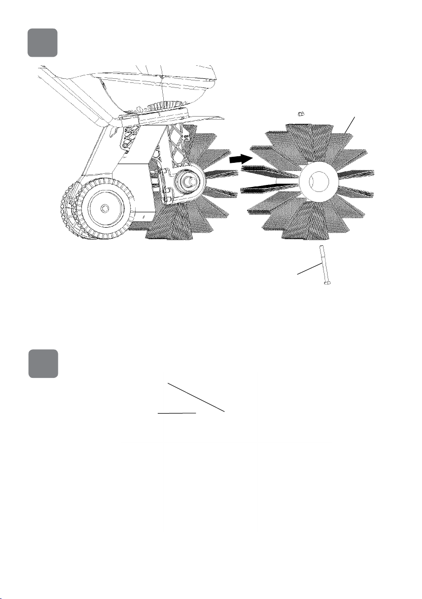
Montaggio
Regolazioni
Manutenzione
Caratteristiche tecniche
Rumore aereo e vibrazioni
Guasti
Pericolo grave per l'incolumità
dell'operatore e delle persone
esposte.
Istruzioni d'uso originali
IT