Euro Towers 750K User manual
TUV CERTIFIED QUALITY SYSTEM
TO ISO 9001:2015
GS PRODUCT APPROVAL TO
BS.EN.1004 3 8/12 XXXD
INSTRUCTIONS FOR USE TO BE
FOLLOWED CAREFULLY
TOWER MAX SAFE WORKING LOAD 750K | PLATFORM MAX SAFE WORKING LOAD 250KG
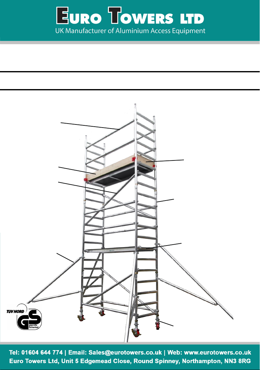
Trapdoor Platform
Diagonal Brace
2M White / Green / Red
2.5M White / Green / Yellow
3M White / Green / Blue
Castor
Adjustable Leg
232 SINGLE WIDTH TOWER
3T - THROUGH THE TRAPDOOR METHOD
AUGUST 21
Side Toe-Board
Multi-Rung Ladder Frame
6, 8 or 10 Rung
Stabiliser
End Toe-Board
Horizontal Brace
2M Black / Green / Red
2.5M Black / Green / Yellow
3M Black / Green / Blue
AUGUST 21
MANUFACTURED BY EURO TOWERS LTD

GENERAL SAFETY RULES
Before You Start
1. Familiarise yourself with these instrucons paying aenon to these safety notes before you use the equipment supplied.
Towers may only be assembled and dismantled by a COMPETENT person familiar with these instrucons.
2. User training courses cannot be a substute for instrucon manuals but only compliment them.
3. This product shall only be used according to the instrucon manual.
4. Only original Euro Towers components specied in this manual shall be used.
5. It is recommended that this user manual be used in conjuncon with a suitable risk assessment and method statement
relave to the project.
6. This instrucon manual shall be available to the USER at ALL mes. Erecon, alteraon or dismantle of the tower should not
be aempted unless the manual is present.
7. This mobile access and working tower shall only be used according to this manual without any modicaon.
8. Mobile access and working towers shall only be used in accordance with naonal regulaons.
9. You will require the following PPE and Tools to help avoid personal injury, Hard Hat, Safety Gloves, Safety Shoes/Boots, Hi Vis
vest/jacket and spirit level.
10. As part of your risk assessment do not begin to erect, move or dismantle your tower in excessive weather condions
including heavy rain, sleet or snow that can aect your an slip surfaces. Also avoid working in extreme heat and high winds.
11. Ensure you selected the correct plaorm height tower in relaon to the desired working height (usually 2m) to avoid over-
reaching and other unsafe pracces.
12. Inspect all individual components before use to ensure quanty, compability, any damages and all parts funcon correctly.
Damaged or incorrect components shall NOT be used.
13. Check the quanty of components supplied corresponds correctly to the king list of the tower height you are planning to
build. Do not start assembly if you do not have the correct number of components. Do not use any tower that has missing or
damaged parts or has not been properly assembled.
14. Erect an exclusion zone and place warning signs if applicable to your locaon of work.
15. It is recommended that a minimum of two person erect, alter and dismantle a tower but during the risk assessment addi-
onal person(s) may be required to perform the task safely.
Inspecon, Maintenance and transport
16. Regularly inspect the individual components to ensure that they are not damaged and funcon properly. Damaged compo-
nents shall be isolated, tagged and removed from use. They should be replaced and sent for repair or scrap.
17. Inspect all tube on frames, stabilisers and braces for dents, cuts and holes, damaged equipment should be isolated, tagged
and removed from use. Check all joints for cracked welds and that they are secure.
18. Inspect Brace Hooks, check the clicker is funconing correctly and the hook is not distorted from abuse. Check the brace is
not bent/dented.
19. Inspect Plaorm for damage to the decking and xings and that (if ed) trapdoor open and close freely and the hinge is
secure. Check the aluminium framework for damage and for cracked welds that may be damaged due to overloading. Check
the hooks are not distorted from abuse and the wind lock clips are aached and funconing properly.
20. Inspect Stabiliser couplers ghten and can be loosened freely. Ensure rubber foot is securely ed and not worn out. Check
for adjusng pins on telescopic stabilisers are ed and secured
21. Inspect castors, checking that the wheel turns and spins freely, that the brakes engage and stops the castor from spinning.
Ensure the castor has no at spots and has a SWL.
22. Inspect the adjustable leg threads are clear of burrs and the nut runs freely up and down the thread. Check the nut housing
for abuse or missing nodules.
23. Light oil or lubricang spray may be used to free up jammed, clickers, castors, adjustable leg nuts, stabiliser couplers,
trapdoor hinges and latches.
24. Do not put excessive loads on the components during storage.
25. When transporng the components do not use excessive strapping forces when securing the load, this may distort and
damage components if not done with care.
Assembling and Dismantling
26. Check ground condions are suitable for erecng and moving the tower and the ground can take the loads imposed by
the tower including weight of equipment and persons. Do not assemble tower on unstable ground such as drain, manhole
covers, compacted ll or any other hazards highlighted during the risk assessment.
27. Check for level and slope of the area where the tower is to be erected, moved and dismantled is within the levelling height
of the adjustable legs.
28. Check for obstrucons that could prevent erecon, moving and dismantling of the tower safely.
29. Check for overhead hazards such as power lines. Do not assemble a tower near uninsulated, live or energised electrical
machinery or circuits, or near machinery or plant that is in operaon.
30. Ensure the Tower is level. Castor wheels should remain LOCKED unless moving the Tower. Adjustable legs are used for
levelling the Tower. NEVER use to gain addional height. Extra height is gained by using addional compable components.
Other items such as ladders, steps, boxes etc should never be used to gain addional height.

31. All components should be passed up or down by hand where possible, where this is not possible use a suitable material
for liing (e.g. Heavy corded rope) and sucient knot es (e.g. hitch knot or mber hitch) DO NOT use mechanical hoists.
32. Towers MUST always be climbed from the inside for access and egress using the Integrated ladders or designated rungs.
NEVER climb the outside of a Tower.
33. Do not lean ladders against a tower or climb the outside. Climb the ladder from the inside as per the supplied access
system and use the trapdoor for access and egress.
34. Never climb on Diagonal or Horizontal braces. Never jump on to or o plaorms
35. Working is only permied on a plaorm with a complete side protecon including guardrails and toe boards.
36. Aer assembly or alteraon, the following minimum informaon shall be displayed on the tower:
a. The name and contact details of the person responsible
b. If the tower is ready for applicaon or not
c. The load class and the uniformly distributed load
d. If the mobile access and working tower is intended for indoor use only
e. The date of assembly
Safe Use & Loadings
37. Before use, check that all components listed in the kit list have been used in the Tower in the correct posion.
38. Care should be taken when using Power Tools or Jet washing or anything specic to your job that could imply side loads
and cause the tower to overturn. Maximum permied side load must not exceed 30kg (300n)
39. When liing components or materials keep within the base of the Tower. Ensure the total weight of the User(s) any
debris, materials being lied does not exceed the Safe Working Load (SWL) of an individual plaorm (250kg) or the overall
structure (750kg) Loads must be uniformly distributed on the working plaorm and not block trapdoors.
40. Mobile access and working towers designed in accordance with EN1004-1 are not anchor points for personal fall arrest
equipment.
41. Work should only be completed from one Working Plaorm at any me complete with Guardrails and Toe Boards to
prevent persons and materials falling from the tower. Work should not be aempted from any other part of the tower
including stairs or braces.
42. The maximum number of person(s) permied on the working plaorm at any me should not exceed the SWL (250kg).
This should include any tools and or materials
43. You should never stand on an unprotected plaorm (guardrails must be in place)
44. Consider measures to secure the tower when le unaended.
Stability & Moving
45. Ensure the Tower is level and the adjustable legs are engaged. Check that you have taken all necessary precauons to
prevent the Tower being moved or rolling away. Always apply ALL brakes or use base plates for stac towers or inclined
surfaces.
46. Ensure that the scaold tower is within the maximum plaorm height as stated and that the appropriate stabilisers are
ed to suit. *Refer to king list.
47. A scaold tower should not be used or moved in wind speeds stronger than 17mph (7.7meters per second) (Beaufort
force 4). If wind speeds exceed this, consider tying the tower to a rigid structure or dismantling before it is exposed to the
strong winds.
48. Beware of the potenal wind factors where there is a possibility for the tunnelling eect of open-ended buildings, unclad
building and at the corners of buildings
49. NEVER t sheets or cladding to a Tower. Such items can act as a sail and impose extreme horizontal load onto a tower
causing it to overturn.
50. When moving a tower plan the route, removing any obstrucons, ensuring the ground can take the weight of the tower.
Beware of so and uneven ground. Pay aenon for overhead hazards and ensure that all materials and persons are
removed from the Tower. If there are any doubts about the route, then dismantle and erect in new locaon.
51. Towers should only be moved manually by pushing at the base of the tower at a usual walking speed. The Tower height
should be reduced to 4m if all 4 stabilisers are in place and 2m if less than 4 stabilisers are in place. Stabilisers are raised
approximately 25mm clear of the ground and then castors are unlocked and the tower can be moved.
52. When the Tower is reposioned reapply the brakes on castor wheels and the tower shall be levelled using the adjustable
legs for both horizontal and vercal alignment. The stabilisers can then be lowered making rm contact with the ground.
53. Towers should NEVER be lied or suspended by a crane or moved by mechanical means
54. Towers are not designed to be used as a means to enter or exit other structures
55. Towers are not designed to be used as a means of edge protecon
56. All towers should be inspected before use.
Further informaon on inspecon and maintenance can be found on Euro Towers inspecon posters. For further
safety informaon or downloading instrucons call Euro Towers or visit our website. www.eurotowers.co.uk
GENERAL SAFETY RULES
MOVING A TOWER Remove people and materials from the tower, and lower the tower to 4m if
all 4 stabilisers are in place. If not then reduce tower height to 2m. Adjust and raise the stabilizers
25mm from the ground, ensure the couplers are tight, and push from at or near the base by manu-
al eort only, never use mechanical means. Recheck level and reposition stabilizers before use.
ALTERNATIVE FRAMES CONFIGURATION: For example where 2 x 8 rung frames are stated
making the tower 16 rungs in total, these can be replaced by 1 x 10 rung and 1 x 6 rung, also
making 16 rungs in total.
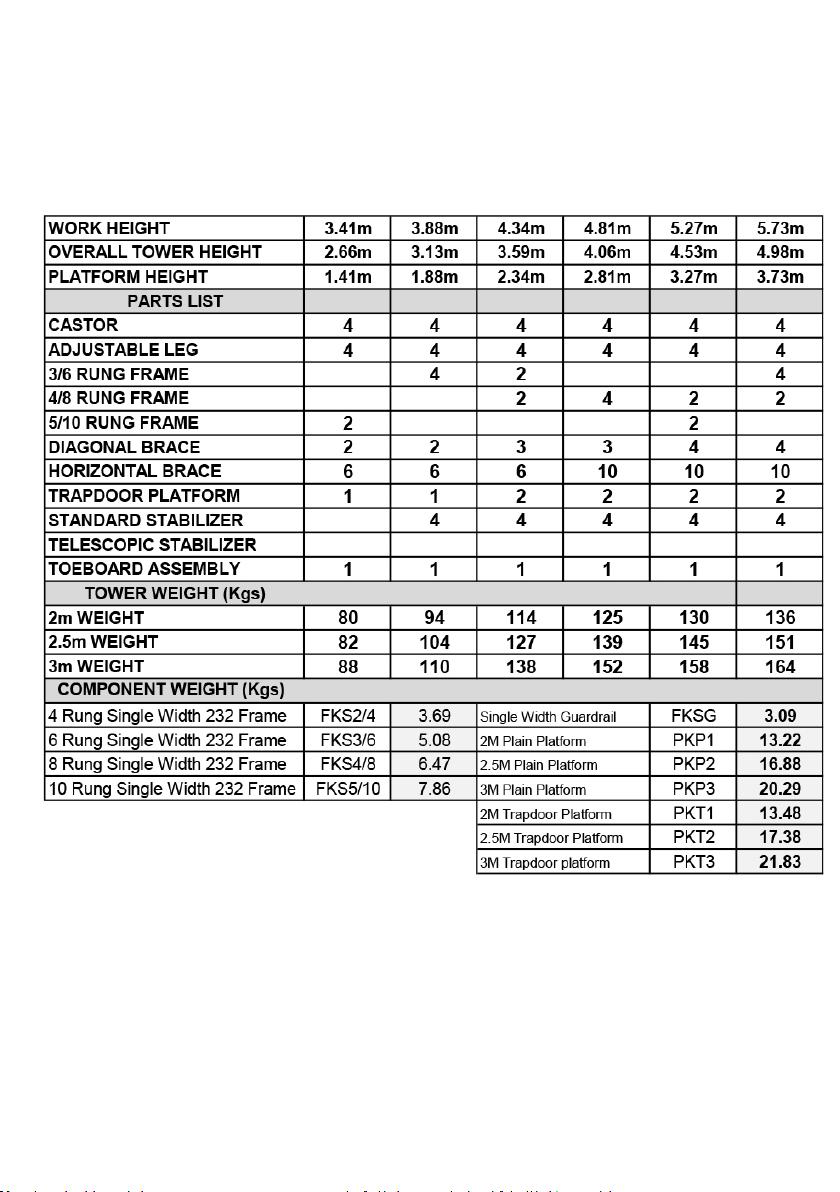
3T 232 MULTI RUNG SCAFFOLD TOWER
SINGLE WIDTH KIT LIST
Available in three lengths: 2m, 2.5m or 3m

0m
1.88m
5.13m
1.41
4.66m
7.91m
PPE REQUIRED: Hard Hat, Safety Gloves, Safety Boots/Shoes, Hi-Viz Vest/Jacket
TOOLS REQUIRED: Spirit Level
SINGLE WIDTH 232 FRAME INSTRUCTION MANUAL
FOR ERECTION, ALTERING & DISMANTLING
The tower requires a minimum of 2 people for assembly
Do not attempt to assemble a tower by yourself
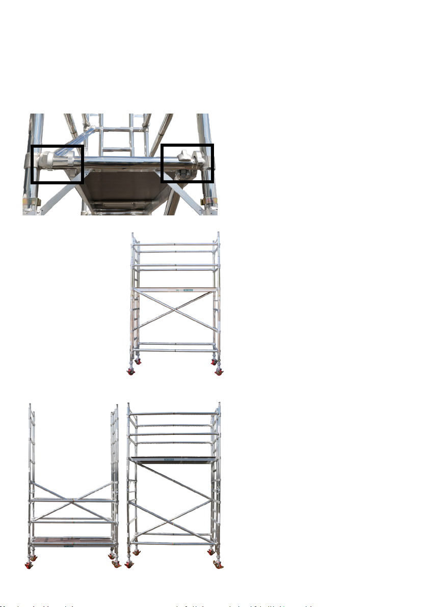
6/8 Rung Base Set Up
For Platform Heights:
2.34m, 4.20m, 6.05m, 7.91m
To achieve platform heights 2.34m, 4.2m, 6.05, or
7.91m you will need to t a temporary platform on
the 1st rung. (See Figure 2)
Fit access platform from 6th rung down on the 8
rung frame from the original temporary platform.
Fit handrails from 3T position. Remove temporary
platform and guardrails then reposition 2
diagonal braces from 1st to 6th rungs in a
alternate patter and install 1 additional diagonal
brace from the 6th to 10th rung. (See gure 3)
6/6 Rung Base Set Up
For Platform Heights:
1.88m, 3.73m, 5.59m, 7.45m,
When using this frame conguration. Start your
diagonal brace pattern from 2nd to 4th in an
alternate pattern. Oset trapdoor platform to one
side allowing a diagonal brace to continue in a
regular pattern.
Bracing Positions
On rungs with two braces and a platform you will
need to have one brace sitting on the inside of the
platform hook and one sitting on the outside of the
platform hook. You will also need to ofset the
platform to one side to achieve this. Alternatively
diagonal braces can be repositioned 1 rung above
or 1 rung below the platform.
Figure 1
Figure 3Figure 2

8/8 Rung Base Set Up
For Platform Heights:
2.81m, 4.66m, 6.52m
To achieve platform heights 2.81m, 4.66m and
6.52m you will need to t a temporary platform
to the 3rd rung down. (See gure 5).
Then Fit 4 horizontal braces from the ground
around the temporary platform. From the tem-
porary platform add both 4 rung frames and t
your platform on the 3rd rung down from the top.
Remove your temporary board and guardrail
braces. Then reposition your diagonal brace to
1st to 3rd and add an additional brace on the al-
ternative side. Finally add an additional diagonal
brace from 3rd to 5th. (See Figure 6)
10 Rung Base Set Up
For Platform Heights:
1.41m, 3.27m, 5.13m 6.98m
Fit platform on third rung down. This base
build does not require repositioning of the
platform.
BASE SET UPS:
WORKING PLATFORM BASE FRAME NEXT
FRAME
FURTHER
FRAMES**
PLATFORM RUNG
POSITIONS
*REPOSITION PLATFORMS WHERE REQUIRED **SEE USING ALTERNATIVE FRAMES NOTE
Figure 4
Figure 5 Figure 6
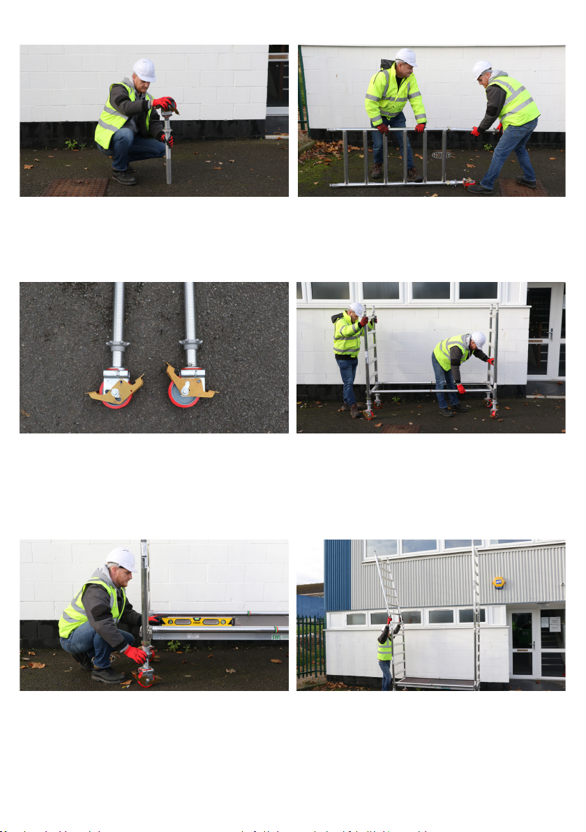
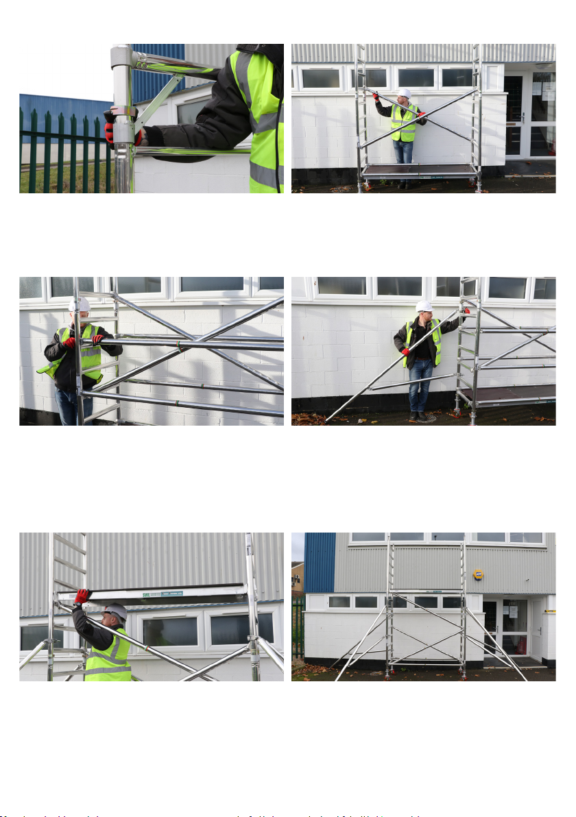
1. Insert castor wheels into adjustable legs 2. Insert 2 adjsutable legs and castor
wheels into each base frame
3. Lock Brakes and allow 3” thread from
bottom of castor for levelling
4. Fit 2 horizontal braces to the verticle
member of the frames above rst rung.
Horizontal braces t on from the inside of
the tower facing outwards
5. Fit 1 plain platform on the appropriate
rung. (See base build for desired platform
height). Level your tower by the adjustable
legs using a spirit level as a guide.
The scaold must be verticle in both planes within an
inclination of 1%
NEVER STAND ON AN UNPROTECTED PLATFORMNEVER STAND ON AN UNPROTECTED PLATFORM
6. Add further frames.
LOCKED UNLOCKED
11. From the temporary platform, t 1
diagonal brace to 3rd rung down and t
trapdoor platform over the hook. Oset
platform to oneside and run the diagonal
brace away from the trapdoor.
12. Remove temporary platform and the 4
horizontal braces. Relocate the 2 diagonal
braces from 3rd to 1st rung.
9. Fit 4 horizontal braces directly above
platform to create your collective
protection. Hooks facing outwards on
frame uprights.
10. Fit 4 stabilisers at earliest opportunity
keeping lower arm as horizontal as
possible.
7. After adding frames always remember to
engage interlock clips
8. Fit 2 more diagonal braces to continue
in a regular pattern on the 3rd rung leaving
room for your horizontal braces to t on the
upright.
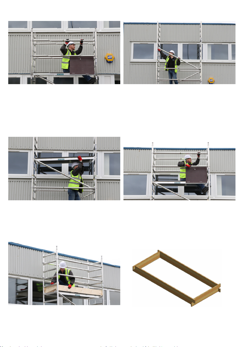
13. From a seated position using the
through the trapdoor (3T) method. Fit 4
horizontal braces, hooks facing outwards
to the frame upright.
14. Continue erecting the tower tting the
frames and diagonal braces as illustrated
using all components. Platforms inserted
every 2m complete with handrails. Braces
run in a continuous pattern on opposite
sides.
15. For your working platform t trapdoor
on the 6th rung down from the top of the
tower.
16. From a seated position, using the 3T
method, t 4 horizontal braces above the
appropriate rungs to the frame verticles,
hooks facing out.
17. Fit toe-boards in correct position

Maximum distance
between platforms
shall not exceed
2.25m except the
distance to the rst
platform max 3.40m
Do not bridge be-
tween towers or oth-
er structures Please
contact Euro Towers
for information on the
correct equipment for
Bridging Towers
Maximum inclination
for movement. Note
the maximum angle
allowed is dened by
the manufacturer
Do not build, disman-
tle or attempt to work
on an access tower if
the wind speed
exceeds 17MPH
Maximum inclination
for movement. Note
the maximum angle
allowed is dened by
the manufacturer
Do not stand on an
unguarded platform
Do not lift the tower
with mechanical
equipment
Do not use the
tower for access
and egress to other
structures
Do not suspend the
tower
Do not lift heavy ob-
jects from the tower
Do not move the
tower with people or
materials on it
Do not use ladders,box-
es or other objects to
gain extra height
Do not climb the outside of the tower
DISMANTLE TOWER IN REVERSE EXCEPT WHEN DISMANTLING THE HANDRAILS
Unclip 4 x Horizontal
braces from the far end of
the trapdoor platform.
From a seated position remove
4 x guardrails making sure you
never stand on an unprotected
platform.
From a seated position descend
down the tower to the next
platform or ground. Ensure you
always have collective protec-
tion around you when standing
on any platform.

Table of contents
Popular Desktop manuals by other brands

HP
HP xw3400 - Workstation Quick reference card

Lenovo
Lenovo ThinkCentre M92z user guide

Mintronix Computer Solutions
Mintronix Computer Solutions MP5000C user guide

HP
HP Z230 SFF Workstation Maintenance and service guide

Compaq
Compaq BL10e - HP ProLiant - 512 MB RAM introduction

Lenovo
Lenovo ThinkCentre A51p Hardware


