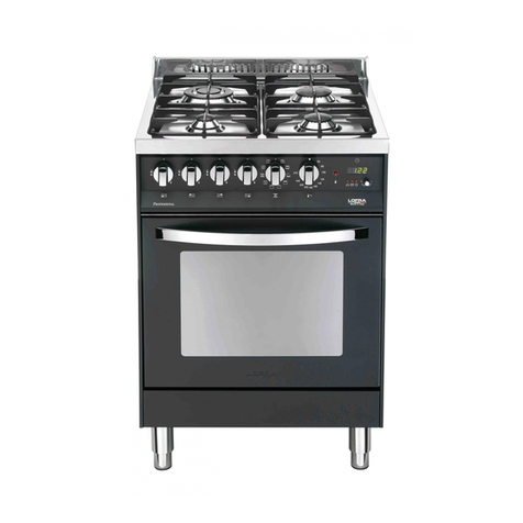
EURO GU 80 NG Reference guide

AGUIDE TO USE,
INSTALLATIONAND REGULATION
OF YOUR COOKER
Models: EGU 80 NG - EG80FS
AUS
MANUFACTURED BY: TECNOGAS

2
461307208 (RS-002)
The appliance was designed and made in accordance with the European standards listed below:
=> EN 30-1-1, EN 30-2-1 and EN 437 plus subsequent amendments (gas)
=> EN 60 335-1 and EN 60 335-2-6 (electrical) plus relative amendments
The appliance complies with the prescriptions of the European Directives as below:
=> 2006/95 EC concerning electrical safety (BT).
=> 2004/108 EC concerning electromagnetic compatibility (EMC)
=> 90/396 + 93/68 EC concerning gas safety.
Oven accessories that could come into contact with foodstuffs are made with materials that comply
with the provisions of the 89/109 EC directive dated 21/12/88.
This product complies with EU Directive 2002/96/EC.
The crossed-out dustbin symbol reported on the appliance indicates that the appliance must be
disposed of separately from other domestic refuse at the end of its useful life. It must therefore be
delivered to a waste recycling centre specifically for electric and electronic equipment or returned to
the retailer at the moment of purchase of a new equivalent appliance.
Theuserisresponsiblefordeliveringtheappliancetotheappropriatecollectioncentreattheendofits
useful life, Failure to do so may result in a fine, as provided for by laws governing waste disposal.
Differential collection of waste products for eventual recycling, treatment and environmentally friendly
disposal helps reduce possible negative effects on the environment and health, and also enables the
materials making up the product to be recycled.
For more detailed information on the available refuse collection systems, refer to the local Municipal
Solid Waste disposal centre or the shop where the product was purchased.
Producers and importers are responsible for fulfilling their obligations as regards recycling, treatment
and environmentally friendly disposal by directly or indirectly participating in the collection system.
CONTENTS
ASSISTANCEAND SPARE PART 3
IMPORTANT NOTESAND PRECAUTIONS FOR USE 4
DESCRIPTION OF THEAPPLIANCE 5-7
INSTRUCTIONS FOR THE USER 8-15
TROUBLESHOOTING 16
INSTRUCTIONS FOR THE INSTALLER 17-24
TECHNICAL FEATURES 25-26

3
461307208 (RS-002)
Before this appliance left the factory it was tested and set by specialized, expert personnel in order to guarantee
the best functioning results.
Any subsequent repairs or adjustments that may be necessary must be done with the maximum of care and
attention by authorised personnel.
Forthisreasonwerecommendyoualwayscontactus(referbelow),specifyingthebrand,model,serialnumberand
type of problem you are having with it. You will find the relative data printed on a label affixed on the appliance and
on the label affixed to the packing box.
IMPORTANT NOTICE
The manufacturer shall not be held responsible for any damage to persons or property caused by incorrect
installation or use of the appliance.
Aduplicatedatalabelandwiringdiagramarecontainedinthisbooklet.Pleaseattachtheselabelstoanaccessible
surface near by the appliance for easy reference.
You can purchase original spare parts from authorised dealers or direct from us.
SPACE FOR DATA LABEL
ASSISTANCE AND SPARE PARTS

4
461307208 (RS-002)
IMPORTANT NOTES AND PRECAUTIONS FOR USE
You have purchased one of our products for which we
thank you. We are confident that this new appliance,
modern, functional and practical, made with top quality
materials,willmeetallyourdemands.Thisnewappliance
is easy to use but before installing and using it, it is
important to read this handbook through carefully.
It provides information for a safe installation, use and
maintenance. Keep this handbook in a safe place for
future reference.
The manufacturer reserves the right to make all the
modifications to its products that it deems necessary
or useful, also in your interests, without prejudicing
its essential functional and safety characteristics.
The manufacturer cannot be held responsible for any
inaccuracies due to printing or transcription errors that
may be found in this handbook.
N.B.: the pictures shown in the figures in this handbook
are purely indicative.
• The installation, adjustments, conversions
and maintenance operations listed in section
«INSTRUCTIONS FOR THE INSTALLER» must only
be carried out by authorised personnel .
• The installation of all-gas and combi appliances must
comply with the standards in force.
• The appliance must only be used for its original
purpose, that is, cooking for domestic use. Any other
use is considered improper and, as such, dangerous.
• The manufacturer cannot be held responsible for
any damage to persons or property resulting from
an incorrect installation, maintenance or use of the
appliance.
• Once the packaging has been removed from the outer
surfaces and the various inner parts, thoroughly check
that the appliance is in perfect condition. If you have
any doubts do not use the appliance and call in an
authorised person.
• The packaging materials used (cardboard, plastic
bags, polystyrene foam, nails, etc.) must not be left
within easy reach of children because they are a
potential hazard source. All packaging materials used
are environmentally-friendly and recyclable.
• Theelectricalsafetyofthisapplianceisonlyguaranteed
if it is correctly connected to a suitable earth system,
as prescribed by the electrical safety standards. The
manufacturer disclaims all responsibility if these
instructions are not followed. Should you have any
doubts, seek the assistance of an authorised person.
• Before connecting the appliance ensure that the rating
platedatacorrespondstothat of the gasandelectricity
supply (see section «TECHNICAL FEATURES»).
• Do not install this appliance on a marine craft or in a
caravan.
There are a few basic rules that must be observed
when using the appliance:
=> Do not use this appliance as a space heater.
=> Do not touch any electrical appliance if hands or feet
are wet or damp.
=> Do not use the appliance bare footed.
=> Do not pull the power lead to take the plug out of the
socket.
=> Do not leave the appliance outside under the sun,
rain, etc.
=> The appliance is not intended for use by young
children or infirm persons unless they have been
adequately supervised by a responsible person to
ensure that they can use the appliance safely.
=> Young children should be supervised to ensure that
they not play with the appliance.
• WARNING - ln order to prevent accidental tipping of
the appliance, for example by a child climbing onto
the open oven door, the stabilizing means must be
installed. Please refer to instructions for installation..
• Before cooking for the first time, ensure the oven
is empty and its door closed, heat the oven at
maximum temperature for two hours. This will allow
the protective coating on the interior of the oven to be
burnt off and dissipate the associated smells. Ensure
adequate ventilation in the kitchen whilst burning off
anddon’tbealarmedbyalittlebitofsmokeduringthis
process.
• WARNING - Accessible parts will become hot when
in use. To avoid burns and scalds children should be
kept away
• Keep the appliance clean. Food deposits could be a
fire risk.
• Avoid using the oven as a larder or as a saucepan
cupboard when you are not using it for cooking: if the
oven is turned on accidentally it could cause damage
and accidents.
• Ifyouareusinganelectricalsocketneartheappliance,
makesurethat the cablesare not touchingthecooker
and are far enough away from all hot parts.
• When you have finished using the appliance check
that all the controls are in the off or closed position,
checking that the “0” of the knob corresponds to the
“•” symbol serigraphed on the front panel.
• Switch off the electrical supply before you start
cleaning or servicing the appliance.
• In the case of a failure or malfunction, turn the
appliance off and switch off the electrical supply and
do not tamper with it. All repairs or adjustments must
be carried out with maximum care and the proper
attention of an authorised person.
For this reason we recommend you call our Service
Centre.

5
461307208 (RS-002)
3
2
1
1
Gv
V
Gf
D
2
3
PRESENTATION
Our cooker is fitted with a fully gas hotplate.
This innovative burner hotplate offers you more scope
and versatility in hotplate cooking than ever before.
The round burners are graduated in their size and
output to provide the exact heat required for every
style of cooking. For example, the large or wok burner
willgiveyoutheintenseheatrequiredforwokcookery,
while the small simmer burner will handle the smallest
of saucepans with ease and safety. The low heat
(simmer) setting is extraordinarily low, so you can
cook the most delicate sauces to perfection.
This innovative, yet very practical combination of
burners allows you to cook an entire meal on the
hotplate at once and is of special assistance when
entertaining.
Each knob on the front panel has a diagram printed
above it showing to which burner it refers.
Our cookers is fitted with a fully gas oven (gas and
grill burner).
The oven walls are fitted with various runners (fig. 1)
on which the following accessories can be placed.
Supply and quantities vary from model to model
(see fig. 2):
• oven shelf rack (Gf). Ensure shelf is located with
dish and tray stop pointing upwards.
• drip tray (V)
• grill rack (Gv)
• handle (D)
The cookers are fitted with a small compartment
under the oven that can be used for storing things.
Remember that the surfaces become hot, it is
strictly forbidden to place inflammable materials
inside.
The door opens by pushing the centre (see fig. 3).
DESCRIPTION OF THEAPPLIANCE

6
461307208 (RS-002)
11 23
23
DESCRIPTION OF THE CONTROLS
HOB GAS BURNER KNOB (A)
By rotating the knob in an anticlockwise direction, the
following symbols appear:
0= Closed position
= “Full on” position
= “Reduced rate or Low” position
GAS OVEN/GRILL THERMOSTAT KNOB (B)
By rotating the knob in an anticlockwise direction, the
following functions appear:
0= Off position
from 125 to 260°C = Oven temperature
Turn the knob clockwise if you want to use the gas
grill .
OVEN LIGHT SWITCH (C)
TIMER (D)
Toset cookingtime,first windthe timer upby turning it
completely once from left to right and then back to the
number of minutes you want. The timer will ring when
the set time has elapsed.
DESCRIPTION OF THEAPPLIANCE
A
125
140
160
180
200
220
240
260
B D E
ELECTRONIC CLOCK (E)
This accessory functions as a clock and a minute
counter. The digital display (L) always shows the time
but will display the minute counter time when this
function is set.
Setting the time (from 0.01 to 24.00 - hh,mm)
Afterconnecting to the electricitymainsor subsequent
to a power cut the figures “0.00” will flash on the
display. Press push button 1 and start setting the
current time by pressing push button 2 or 3. The
function will start 7 seconds after setting.
Minute counter (from 0.01 to 0.99 = hh,mm)
By selecting the time on the minute counter with push
button3,thisfunctionwillbeactiveallofthetime(timeis
set in 10 second units). The time will disappear leaving
the minute counter time showing on the display and the
symbol lights up. Time is given in seconds during
countdown. At the end of the set time the buzzer goes
off,the symbol disappears andthe time reappears.
You can see the time while the minute counter is
functioning by pressing push button 1.
Buzzer
The buzzer goes off at the end of the minute counter
functionandlastsabout 7 minutes. The buzzer can be
stopped by pressing button 3.
Buzzer intensity
There are three different buzzer intensities: to select
the one you want press push button 2 when the time
is displayed.
Correcting/cancelling the minute counter function
Tocorrectorcancelthetimesetontheminutecounter,
press keys 2 and 3 simultaneously and then release
key 3 first. The time can be corrected at any moment
by pressing push button 1 followed by 2 or 3.

7
461307208 (RS-002)
HOB: GENERAL NOTES ON SAFETY
• Whenusingtheburners,donotleavetheappliance
unsupervised. Ensure that children do not play with
the appliance. In particular, make sure that pan
handles are positioned correctly and supervise the
cooking of foods which use oils and fats, as these
are highly inflammable.
• Do not use aerosols or sprays near the appliance
when it is in use.
• Even after use, the burners remain hot for a long
period; to avoid burning, do not place hands or
other objects on them.
• If the appliance is fitted with a lid, remove any food
residues on the surface before opening.
• If the appliance is fitted with a crystal glass lid, this
can shatter when heated. Turn off all the burners
and to attend that is cooled, before closing the lid
(fig. 4).
• Theglass lid is not to be usedasa cooking surface,
ensure that it is fully raised when the cooktop is in
operation.
• Afterusingtheappliance,ensurethatallthecontrols
are in the closed or off position.
AUTOMATIC ELECTRIC IGNITION OF COOKTOP
BURNERS
Push lightly the knob (ref. A) corresponding to the
burner you wish to use and turn anti clockwise to
the “Full on“ position, then depress the control knob.
Automatically the ignition spark shoots.
MANUAL IGNITION OF COOKTOP BURNERS
Manual ignition may be necessary in the event of
power failure or component malfunction. Place a lit
match close to the selected burner, and repeat the
above steps.
INSTRUCTIONS FOR THE USER
OPTIMUM USE OF COOKTOP BURNERS
In order to achieve maximum efficiency with minimum
gas consumption it is useful to remember:
• Donotuselargeburnerswithpansofsmalldiameter
in order to avoid flames spreading wider than pans
(consult the following table) and always use pans
with lids (see fig. 5).
• When the boiling point is reached, it is best to turn
the knob to the “Low position”.
• Avoid using over sized pans that may radiate
excessive heat and cause damage to surrounding
surfaces such as bench tops and glass lid.
• The appliance can be equipped with a particular
central or left hand side pan support (1) on which
must be put the wok support (2). To ensure stability,
position the notch (A) of wok support on the pan
support fingers as indicated in fig. 6.
• Do not place anything, e.g. flame tamer, asbestos
mat, between pan and pan support, as serious
damage to the appliance may result (fig. 7).
• Locatepancentrallyovertheburnersothatisstable
and does not overhang the appliance (fig. 8).
• If gas burns with a yellow flame, do not continue to
use burner and arrange for service.
• Do not use burners without the proper pan support or
wokstand,asthiswillconcentrateanddeflecttheheat
ontothehotplate(fig.9)andsurroundingsurfaces.
• Use only a wok support supplied or recommended
by the manufacturer of the appliance (fig. 10).
ABNORMAL OPERATION
Any of the following are considered to be abnormal
operation and may require servicing:
• Yellow tipping of the hob burner flame.
• Sooting up of cooking utensils.
• Burners not igniting properly.
• Burners failing to remain alight.
• Burners extinguished by the oven door.
• Gas valves, which are difficult to turn.
Incase the appliancefailsto operate correctly,contact
our Service Centre.
Warning: Servicing should be carried out only
by authorised personnel.
Burners Ø pan cm
Ultrarapid or Wok 22÷24
Rapid 20÷22
Semi-rapid 16÷18
Auxiliary 12÷14
4

8
461307208 (RS-002)
INSTRUCTIONS FOR THE USER
8
7
9
5
1
2
A
6
10

9
461307208 (RS-002)
INSTRUCTIONS FOR THE USER
OVEN: GENERAL SAFETY INSTRUCTIONS
• Do not leave the oven unsupervised during use. Ensure that children and the infirm do not play with the
appliance.
• Always keep the appliance lid open when using the ovenor grill burner, in order to prevent overheating.
• Do not spray aerosols in the vicinity of this appliance while it is operating.
• Where this appliance is installed in marine craft or in caravans, it shall not be USEDASASPACE HEATER.
• Alwaysgrip the centre of the oven door when opening. Do not practiceexcessivepressuresonthe door when
it is open.
• Do not store or use flammable liquids or items in the vicinity of this appliance.
• Donotworryifcondensationforms onthe doorand ontheinternalwallsoftheoven duringcooking.This does
not compromise its efficiency.
• When opening the oven door, be very careful of scalding vapours.
• During use the appliance becomes hot. Care should be taken to avoid touching heating elements inside the
oven.Wearoven gloves when placingor removing pans fromthe oven or usethe handle (D) (fig.2) provided.
Hook the handle to the edge of the tray and pull it out, slightly lifting it as you do so.
• When inserting or removing food from the oven, check that excess juices do not overflow onto the oven base
(oils and fats are highly inflammable when overheated).
• Use containers that will resist the temperatures indicated on the thermostat knob.
• Never cover the base of the oven or the oven shelf with aluminium foil or other materials, as this creates a fire
hazard.
• When grilling always put a little water in the grill pan. The water prevents the grease from burning and from
giving off bad smells and smoke.Add more water during grilling to compensate for evaporation.
• After using the appliance ensure that all the controls are in the off position.
• WARNING - During and after use, the oven door glass and the accessible parts will become hot when
in use. To avoid burns and scalds children should be kept away.
IMPORTANT!!
Always keep the oven door closed during baking. It must only be left partially opened when using the
gas grill burner (see relative instructions).
WHAT TO DO THE FIRST TIME YOU USE THE OVEN
• Remove all protective wrapping materials from the appliance and labels from the oven door.
• Remove combustible materials from the warming compartment before commissioning the cooker.
• Before cooking for the first time, heat the oven at maximum temperature for 2 hours. This will allow the
protectivecoating on the interiorofthe oven to beburntoff and expel theassociatedsmells. Ensure adequate
ventilation in the kitchen whilst burning off and don't be alarmed by a little bit of smoke during this process.
Attheend of this time period, allow the appliance to cool down and then clean the interior using hot water and
a delicate detergent. Also wash all the accessories (grills, trays, spit roast, etc.) before use.
Prior to any cleaning, disconnect the appliance from the electricity mains.

10
461307208 (RS-002)
B
C
12
S
11
HOWTOUSEGASOVENANDGASGRILL
The appliance is equipped with an aluminium shield (S), which works in order to obtain a burnishing
uniform above all during the baking of cakes and biscuits. The shield must be correctly positioned on
the oven bottom plate (see fig. 11) during oven operation.
AUTOMATIC ELECTRIC IGNITION OF OVEN BURNER
Electric ignition is achieved by firstly, fully opening the oven door, removing the shield (S) (fig. 11) and then
pushing and turning the ovenl knob (ref. B) anti clockwise to the maximum temperature position, then depress
the knob. Automatically the ignition spark shoots.
Checkthroughtheopening(C)(fig.12)that ithasignited.Continuetopushgascontrolknobfor15 secondsafter
ignition has occurred. If ignition does not occur, turn gas control knob off, open the warming compartment door
and wait 60 seconds to allow gas to disperse, then repeat ignition procedure.
Note: At the end of this operation, correctly put again the shield (S) (fig. 11). Take care to not scratch the
enamel of the bottom plate, moving this shield.
MANUAL IGNITION OF THE OVEN BURNER
Intheeventof powerfailure orcomponent malfunction,manual ignitionoftheovencan beobtained byrepeating
the above steps, but instead of pushing ignition button or control knob, placing a lit match at the access hole (B)
in the bottom plate (see fig. 12).
INSTRUCTIONS FOR THE USER

11
461307208 (RS-002)
USING THE OVEN
Having ignited the oven, the gas control knob should be adjusted to the desired temperature and the oven door
left open for 2 to 3 minutes and then gently close the door to avoid extinguishing the flame. Preheat the oven for
approximately 15 minutes.
Yourappliance’sheatcirculationpatternisquitedifferenttomanyothercookers.Itemploysaningenious,natural,
“Rapid Draught” convection system. Hot air is efficiently circulated through the oven very quickly producing
relatively even heat zoning.
With planning and a clear understanding of your appliance’s characteristics and capabilities you will be able to
produce superb results and larger than normal quantities. However in order to obtain maximum efficiency it is
useful to remember:
• Cooking times and shelf positions will probably be different from your previous oven. The size and type of
dishesused will affect cooking times andtheuseof aluminium foil will increase cookingtimes.Werecommend
doingatestbake,andcomparingthe timesinthe timeandtemperaturecharttosomeofyourfavouriterecipes.
Add 10 to 15 degrees C when cooking larger quantities. Shelves are numbered from the bottom (see fig. 1).
• Be sure to remove the enamelled grill tray when the oven is in use. It is not intended to be used for baking or
roasting purposes and it can interfere with heat distribution in the oven.
• Thelarger capacityovensof theyourappliance willrequireslightly highercookingtemperatures thanasmaller
oven. Add between 5-10 degree C.
• Slightly more heat is generated from the bottom of the oven upwards, with the top shelf being the marginally
cooler zone. This is the reverse of other ovens you may have used and some minor adjustment to your
cooking methods with some dishes may be required. Most baking would be done on the middle shelves, with
the lower shelves being used for a greater degree of base browning.
• Always preheat the oven when cooking frozen or chilled foods.
• Best results are achieved when preparing large quantities or using two shelves simultaneously by positioning
serves with an "air space" around. More even cooking can be made possible if two medium sized baking
trays are used per shelf, leaving a 3-4 cm "air space" between the trays and from the trays to the oven wall.
A single larger tray may divert or block the usual flow of hot air around the oven. When using two shelves
simultaneously allow an "air space" by leaving one shelf space empty between.
• Youcan plan batch baking to make the mostefficient useofthehotter and cooler zones, by cooking a different
food requiring slightly different temperature on each shelf e.g. small cakes and slab cakes, or two different
types of biscuits (refer to the chart on pag. 12).
• Light weight, uncoated aluminium trays and pans are recommended for general cooking. Heavy gauge and
dark coloured utensils do attract extra heat and may be unsuitable for some foods.
• The aluminium can be easily corroded if it comes into contact with organic acids present in the foods or added
during baking (vinegar, lemon juice). Therefore it is advised not to put directly the foods on aluminium or
enamelled trays, but ALWAYS use the proper oven paper.
Contact our Service if assistance is required with cooking results or thermostat operation appears
incorrect.
INSTRUCTIONS FOR THE USER

12
461307208 (RS-002)
INSTRUCTIONS FOR THE USER
TIMEAND TEMPERATURE CHART
Because of the large capacity of the oven, higher temperature are used; i.e. 10-15°C higher than in a standard
oven. This general description of the oven setting will help you:
cool oven 125-140°C moderately hot 210-220°C
slow oven 150-160°C hot 230-240°C
moderately slow 170-180°C very hot 250-260°C
moderate 190-200°C
The above table gives guidelines for cooking a range of different foods, individual food, or personal preferences
may slightly vary the oven position, temperature and cooking time from those suggested. Please note that:
• All cooking temperatures stated refer to a preheated oven (allow 15 minutes for preheating).
• The shelves are numbered from the bottom i.e. the top shelf is Shelf 3, the bottom shelf is Shelf 1.
• If baking a larger quantity than the example shown in the chart, slightly increase temperatures and/or time.
• If baking a smaller quantity than the example, slightly decrease the temperature and/or time.
• Remenber to remove grill tray from oven before baking in oven.
FOOD ITEM QUANTITY OVEN
POSITION TEMPERATURE
°C APPROXIMATE
TIME
CAKES
Patty cakes - 2 trays
Sponges
Butter cake - slab
Boiled fruit cake - 20 cm tin
Rich fruit cake - 20 cm tin
36
4 or 6
1
2
1
1
Shelf 2
Shelf 2
Shelf 2
Shelf 1 or 2
Shelf 1 or 2
Shelf 2
200
190
190
200
160
150
15-20 mins.
20-25 mins
30-35 mins.
35-40 mins.
2 hrs.
4 hrs.
SCONES - plain,
2 trays 40 Shelf 2
Shelf 1 & 3 240
240 10-12 mins.
12-15 mins.
BISCUITS
Anzacs - 2 trays
- 4 trays
Burnt butter biscuits - 4 trays
24
50
60
Shelf 1 or 2
Shelf 1 & 3
Shelf 1 & 3
160
160
190
20 mins.
25 mins.
20 mins.
MERINGUE - small, 2 trays 30 Shelf 2 125 1-1½ hrs.
allow to cool in oven
PASTRIES
Custard tart - 23 cm
Fruitpies-biscuitpastry,doublecrustcooked
filling
Sausages rolls
1 or 2
1 or 2
40
Shelf 1 or 2
Shelf 2
Shelf 2
220/180
220/190
230
10/40-50 mins.
15/15-20 mins.
20-25 mins.
PIZZA - yeast dough 30 cm 1 Shelf 1 or 2 240 20-25 mins.
OVEN MEAL
Roast meat & vegetables
Fruit pies 2Shelf 1 or 2
Shelf 1 or 2 210 as requested
50-60 mins.
BREAD 1 loaf Shelf 1 or 2 200 35-40 mins.
RETAIN THIS CHART FOR EASY REFERENCE
ROAST MEATS
Meats are generally roasted in the centre of the oven (shelf 2) but the position may be varied according to the
size of the meat and the other foods to be cooked at the same time.
A moderate temperature can be used (200°C) although superior results are often achieved by cooking meat
quickly at a high temperature e.g. 250°C for 30 minutes to sear the meat, then complete the cooking on a
moderate heat. Turkey or other very large joints of meat may be cooked at lower than moderate temperatures.

13
461307208 (RS-002)
13
INSTRUCTIONS FOR THE USER
AUTOMATIC ELECTRIC IGNITION OF THE GRILL
BURNER
Automatic ignition is achieved by firstly, fully opening
the oven door and then pushing and turning the gas
control knob (ref. B) clockwise to the grill setting, then
then depress the knob. Automatically the ignition
spark shoots. Continue to push gas control knob for
15 seconds after ignition has occurred. If ignition does
not occur, turn gas control knob off, open the warming
compartmentdoorandwait60seconds toallowgas to
disperse, then repeat ignition procedure.
MANUAL IGNITION OF THE GRILL BURNER
Intheeventofpowerfailureorcomponentmalfunction,
manualignitionofthegrillcanbeachievedbyrepeating
theabovesteps,butinsteadofpushingignitionbutton,
placing a lit match at the grill burner.
USING THE GRILL
• The grill is located in the top of the oven and makes
for an extremely versatile and controllable method
of cooking.
• Preheat the grill for a few minutes for quicker
cooking and more succulent results.
• The food should be seasoned before cooking. Oil
or melted butter should also be spread on the food
before it is cooked.
• Foodstobegrilledshouldbeplacedonthegrillrack
(Gv) positioned in the drip tray (V) or directly on the
shelf (Gf) (fig. 2).
Then place this on the oven shelf required and use
the drip pan to catch the gravy .
• When grilling always put a little water in the grill
pan. The water prevents the grease from burning
and from giving off bad smells and smoke. Add
more water during grilling to compensate for
evaporation.
• With gas grill the oven door must be left
partially opened at its preset hold position and
you must ensure that the protective heat guard
(fig. 13) is correctly fitted to protect the controls and
facia panel. Take care when later removing the hot
protective heat guard.
• The grill offers a fixed heat setting but, a great
degree of heat control is possible by selecting the
most suitable oven shelf position for grilling the
particularfood.Thelowertheshelf,theless intense
the heat. This ability to adjust shelf positions also
allows for a range of bulky foods to be prepared
under the grill which ordinarily couldn't be prepared
in a standard grill compartment.
• Use Shelf 3 for thick cuts of meat, fish fillets or
chicken pieces. Use Shelf 2 for larger portions of
foods, such as half chicken, whole fish or browning
the tops of casserole dishes etc.
• The large grill tray allows an array of foods to be
prepared under the grill. The most intense heat is
directly beneath the grill burner. Foods requiring
moregentleheatcanbeplacedaroundtheperimeter
of the tray where heat is not quite as intense, for
example, seafood or vegetable kebabs, savouries,
warming hamburger buns or keeping foods warm.

14
461307208 (RS-002)
H
Q
1514
CLEANINGAND MAINTENANCE
• Prior to any maintenance work or cleaning, disconnect the appliance from the electricity mains.
• Do not use a steam cleaner to clean a hob, oven or range.
• Do not wash the parts if they are still hot.
• Do not use metal pads, abrasive powders or corrosive spray products for cleaning
• Do not leave vinegar, coffee, milk, salty water or the juice of lemon or tomato on enamelled surfaces
for any length of time.
HOT PLATE
To keep the surface of the hob and the various components in pristine condition (grill, enamelled covers, burner
heads and flame diffusers, it is very important to wash them in warm soapy water, rinse and dry them well after
each use.
IMPORTANT
Comply with the following instructions, before remounting all parts:
• Position the burner skirts as indicated in fig. 14.
• Verify that the holes of flame ring are not obstructed by any residue and that stop notch (H) on the flame ring
itself, has been correctly positioned on lip (Q) (see fig. 15).
• Take care not to disturb the ignition spark plugs or eventually flame failure devices.
• Do not force the taps if they are difficult to open. Contact the technical assistance service for repairs.
INSTRUCTIONS FOR THE USER

15
461307208 (RS-002)
C
L
16
STRUCTURE
All the cooker parts (in enamelled or painted metal, steel, or glass) should be cleaned frequently with warm soapy
water and then rinsed and dried with a soft cloth.
DO NOT use harsh abrasive cleaners or sharp metal scrapers to clean the oven glass door since they can
scratch the surface, which may result in shattering of the glass. NEVER use sponges or abrasive products, and
aromatic or aliphatic solvents to remove stains or adhesives on the painted or stainless steel surfaces.
OVEN CAVITY
Do not spray or wash the thermostat bulb with acid based products (check the product label before
use). The manufacturer cannot be held liable for any damage caused by incorrect cleaning.
The oven cavity should be cleaned after each use to remove cooking residuals and or grease or sugar which, if
burnt on when the oven is used again, will form deposits or unremovable stains as well as unpleasant smells.
Tomaintain the shineoftheenamelled parts, cleanthemwith warm soapy water,rinseand dry them thoroughly.
ALWAYS wash the accessories used.
Note: At the end of this operation, correctly put again the shield (S) (fig. 11). Take care to not scratch the
enamel of the bottom plate, moving this shield.
OVEN SEAL
The oven seal guarantees the correct functioning of the oven. We recommend you:
• clean it, avoiding abrasive tools or products.
• check its state now and then.
If the oven door seal has become hard or is damaged, contact our Service Centre and avoid using the
oven until it has been repaired.
REPLACING THE OVEN LAMP (fig. 16)
Ensure the appliance is switched off before replacing the lamp to avoid the possibility of electric
shock.
In the event oven lamp need replacing, the new lamp must comply with the nominal data indicated on page 25
and must be resistant to high temperature (300°C). Turn glass protection cap (C) counterclockwise and change
the lamp. Re-fit the cap, screwing it back in a clockwise direction.
INSTRUCTIONS FOR THE USER

16
461307208 (RS-002)
Some problems can be caused either as the results of simple maintenance operations or by incorrect selection
of settings. Prior to contacting a Service Centre please check the following chart.
PROBLEM REMEDY
The appliance is not working • Make sure the gas cock is open
• Check the plug is in
• Check that the knobs are set correctly for cooking and then repeat the
operations given in the handbook
• Checkthe electricalsystemsafety switches(RCD).If there isfailure in
the system call an electrician in.
The thermostat is not working • Contact Service Centre..
The oven light does not switch on • Make sure the lamp is firmly screwed in place
• Buy a lamp for high temperatures at one of our Service Centre and fit
it following the instructions given on page 15.
Any of the following are considered to be abnormal operation and may require servicing:
• Yellow tipping of the hob burner flame.
• Sooting up of cooking utensils.
• Burners not igniting properly.
• Burners failing to remain alight.
• Burners extinguished by cupboard doors.
• Gas valves, which are difficult to turn.
In case the appliance fails to operate correctly, contact our Service Centre.
Warning: Servicing should be carried out only by authorised personnel.
TROUBLESHOOTING

17
461307208 (RS-002)
TECHNICAL INFORMATION
The installations, conversions and maintenance operations listed in this part must only be carried out
by authorised personnel. The manufacturer cannot be held responsible for any damage to persons or
property resulting from an incorrect installation of the appliance.
• The safety and automatic adjustment devices of the appliances may, during its life, only be modified by the
manufacturer or duly authorised supplier.
•This appliance shall be installed only by authorised personnel and in accordance with the manufacturer’s
installation instructions, local gas fitting regulations, municipal building codes, electrical wiring regulations,
AS 5601 - Gas Installations and any other statutory regulations.
• Failure to install the appliance correctly could invalidate any manufactures warranty and lead to prosecution
under the above quoted regulation.
• Before installation, make sure that local distribution conditions (gas and electrical) are compatible with the
appliance’s adjustment. Refer to data label for gas type.
• As it is not connected to a device for the evacuation of the products of combustion, it must be installed in
accordancewithcurrent regulations and used in a well ventilated location. Particular attention must bepaid to
the regulations on ventilation.
VENTILATION
All rooms require an openable window or equivalent, while some rooms require a permanent vent in addition to
the openable window.
Ventilation must be in accordance with AS5601 - Gas Installations. In general, the appliance should have
adequate ventilation for complete combustion of gas, proper flueing and to maintain temperature of immediate
surroundings within safe limits.
The use of a gas appliance results in production of heat and moisture in the room in which it is installed. Ensure
that the kitchen is well ventilated; keep natural ventilation holes open or install a mechanical ventilation device
(mechanical extraction hood).
Prolonged intensive use of the appliance may call for additional ventilation, for example increasing the level of
mechanical ventilation where present.
UNPACKING YOUR COOKER
• Oncethepackaginghasbeenremoved,thoroughlycheckthattheapplianceisinperfectcondition.Ifyouhave
any doubts do not use the appliance and call our Service Centre.
• Do not move the appliance by the handles.
• Somepartsmountedontheapplianceareprotectedbyaplasticfilm.Thisprotectionmustberemovedbefore
using the appliance. We recommend slitting the plastic film along the edges with a sharp knife or pin.
The packaging materials used (cardboard,plastic bags, polystyrene foam, nails etc.) must not be left
anywhere within easy reach of children as they are a potential hazard source.
INSTRUCTIONS FOR THE INSTALLER

18
461307208 (RS-002)
+ 5 mm
750 mm
100 mm
17 18
INSTRUCTIONS FOR THE INSTALLER
POSITION (fig. 17)
The appliance should be positioned in good light and free from draughts.
Any adjoining wall surface situated within 200 mm from the edge of any hob burner must be a suitable non-
combustiblematerial for a height of 150 mm fortheentirelength of the hob. Any combustible construction above
the hotplate must be at least 750 mm above the top of the burner and no construction shall be within 450 mm
above the top of the burner.
Where a combustible surface adjacent to the cooker is less than 200 mm from the nearest burner it may be
protected by a non-combustible protective layer in accordance with AS5601. The protection must ensure the
surface temperature of the combustible surface does not exceed 65º C above ambient.
LEVELLING THE COOKER
• Spacers, positioned behind the rear panel to keep the appliance at the minimum required distance from the
back wall. These must not be removed.
• Adjustable feet, to be fitted to the appliance, which allow the height of the cooker to be aligned with other
kitchen furniture. In order to level the cooker, adjust the feet (fig. 18), unscrewing up or down as required.

19
461307208 (RS-002)
timber
Hook Hook
Masonary
wall
Masonary
plug
Wall
Anti Tilt hook
Hose Assembly
hook
plaster
Position of hook
770 mm + - 5
20 mm + - 3
100 mm + - 5
Position of hook
19
SECURING THE COOKER TO WALL (fig. 19)
Note:- The installation of the chain provided is for safety reasons, it must be installed as indicated
below.
To prevent the cooker tipping forwards in the event of children standing on the oven door or where users put
extreme weight on the door when in open position, two lengths of chain MUST BE fixed to the back of the oven
which should at all times be secured to the hooks provided. The hook should be secured to the wall at the back
ofthecooker.Thechainsshouldalwaysbeattachedtotheupperhookswhenthecookerisinitspositionagainst
the wall. Attach the chain to the lower hooks if the cooker is installed with a hose assembly so that there is no
strain on the hose when the cooker is pulled forward for cleaning or maintenance.
WARNING: If the cooker is installed between two cupboards and the stabilising chains cannot be installed to
stabilise the cooker, please contact our Service Centre.
Assembly instructions
• Fix hook into wall immediately behind and to the left-hand side about 770 mm from the floor.
• Secure the chain to the hook before using or cleaning etc. of the cooker (see figure 19).
• To prevent strain on the Flexible Hose assembly, a chain & hook is necessary approx. 100 mm up from the
floor.
INSTRUCTIONS FOR THE INSTALLER

20
461307208 (RS-002)
GAS CONNECTION
Thisapplianceshallbeinstalledonlybyauthorisedpersonnelandinaccordancewiththemanufacturer’sinstallation
instructions, local gas fitting regulations, municipal codes, electrical wiring regulations, AS 5601 - Gas Installations
and any other statutory regulations.
The appliance is adjusted to work at gas indicated on the label which is applied on the glass-window of the oven
door and on the cooker packing.
Installation for Natural gas
Connected regulator (B) to fitting (A) which is then fitted to elbow (F). Ensure arrow on regulator point in the
direction shown. Fitting (D) to be supplied by installer (fig. 20). Adjust regulator to give test-point pressure given
on data label and on page 25, with one large or one medium burner alight at maximum.
Position of Regulator
Ifstove istobe installedon legs, agas pipebetweenfitting(A) and(B) (fig.20)will allowlocationof theregulator
(B) underneath the stove for adjustment and maintenance. If stove is installed on it’s base, the regulator should
be fitted at rear of stove on fitting (E) (fig. 20) for maintenance and adjustment.
Note: When the regulator is fitted at the rear of the cooker at least 60 mm clearance is required.
Installation to L. P. Gas
Connect by using a copper pipe starting, from the threaded fitting of elbow (F) (fig. 21).
When converting fromNatural Gas toPropane ensurethat the NGregulator is removedand replaced withthe Test
Point Assembly. A gas regulator suitable for a supply pressure of 2.75 kPa should be part of the gas tank supply.
Installation using flexible connection
Asanoption,thecookermaybeinstalledwithaflexibleconnectionhose,whichcomplieswithAS/NZS1869(AGA
Approved), 10 mm ID, class B or D, Minimum 1000 mm - Maximum 1200 mm, as an alternative connection.
• All cookers offer left or right hand connection. The manifold has a flat flair over which is inserted a screw nut
male ½” gas.
• An isolating tap and pressure regulator must be fixed to the rear wall and the flexible pipe attached by means
of a union connector.
• The gas connection and isolating tap must be accessible to a service person or inspector.
• Thehoseassemblymustbe installedinaccordancewithAS5601forahighlevelconnection.Thehoseshould
not be subjected to abrasion, kinking or permanent deformation and should be able to be inspected along its
entire length. Unions compatible with the hose fittings must be used and connections tested for gas leaks.
The fixed consumer piping outlet should be at approximately the same height as the cooker connection point,
pointing downwards.
• Thehoseshouldbe clearofthe floorwhenthecookerisintheinstalledposition.The anti-tiltingchainsupplied
shouldbeanchoredtothelowerhookfixedtothewallsothatthechainpreventsstrainonthehoseconnections
when the cooker is pulled forward.
INSTRUCTIONS FOR THE INSTALLER
F E
C
A
B
D
20
A
C
FCE
T
21
This manual suits for next models
1
Table of contents
Other EURO Cooker manuals
Popular Cooker manuals by other brands
Bosch
Bosch HG 120B Series User manual and installation instructions

Belling
Belling 100 EI user guide
JUNO
JUNO JGS 1000 Instruction booklet
Parkinson Cowan
Parkinson Cowan 311330813 Owners handbook and installation instructions

Belling
Belling 644 Installation and user instructions
Pelgrim
Pelgrim PF6220 Instructions for use
