Eno Open Sea 1413 User manual

Minimum safety zone to be lined/protected with fire-proof materials (According to ISO / 9094-1.2 Art.
4.2.1.5)
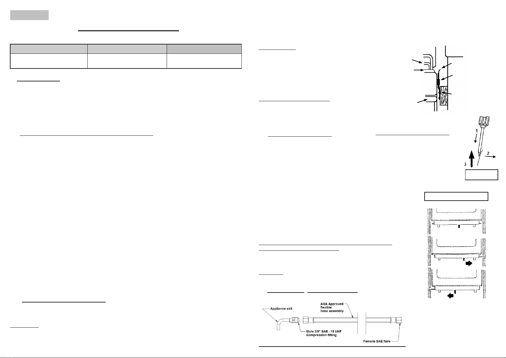
The gas inlet connection is located on the back of the stove approximately 100mm from the bottom and
80mm from the left side of the stove; as shown on the diagram above (Fig.1). FIG. 1
SERVICE CONTRÔLE:
95, Rue de la Terraudière
79000 NIORT
FRANCE
: + 33 (0)5 49 28 60 15
Fax: + 33 (0)5 49 33 26 84
eno @ eno.fr http://www.eno.fr
"Open Sea”
"Oc
ean"
"Gascogne"
INSTRUCTIONS FOR USE
1312 AGA 6744 G
Australian Gas Association Approved
FIG. 2
How to lock the anti-rolling bar on the right or on the left
Ref. : 87955 C
(2017 - 07)
Model :
1413, 1423, 1433, 1463
Model :
1813, 1823, 1833, 1863
ENGLISH 2 / 3 BURNER COOKER
Destination country
Pressure (kPA)
Gas
Australia
2.75
LPG (propane) only
I - INTRODUCTION
The ENO marine cooker you have just acquired is designed for pleasure boating.
It is equipped with a 25 litre oven fitted with a ‘U’ shaped burner and two top burners of 2500W and 1750 Watts. Models
with a grill burner have a 19 litre capacity (Paragraph VIII).
ENO’s marine cookers are fitted with a thermocouple safety device on each burner (cooker and oven) and a 1.5V
electronic ignition device.
If the flame goes out, the gas supply is automatically cut off.
ENO marine cookers are equipped with a pan-holder set and a door locking device.
II –INSTALLATION AND MAINTENANCE CONDITIONS
This appliance shall be installed and maintained by an authorized person.
- DO NOT MODIFY THIS APPLIANCE.
This appliance is not connected to an exhaust flue: it must be installed and connected in compliance with the relevant
Installation Rules. Especially respect the Regulations concerning aeration. This appliance shall only be installed only by
an authorised person and in accordance with the manufacturer installation instructions, local gas fitting regulations,
municipal building codes, with reference to AS 5601 and any other statutory regulations that are applicable.
- Gas installations on board
For commercial marine craft, refer to uniform Shipping Laws Code, which should be read in conjunction with AS5601:
- The minimum air inlet necessary to a proper combustion is: 2 m³/h per kW power.
- Horizontal distance between the appliance and the adjacent walls shall not be less than 20 mm.
Installation and maintenance of this appliance have to be carried out by a skilled person in accordance with the relevant
Regulations, in particular:
- The User has to comply with Technical and Safety Rules prescriptions concerning use of inflammable gas and liquefied
hydrocarbons in houses and outbuildings, stipulating that no unit should be installed in any room unless:
a sufficient air inlet and outlet
a minimum volume of 8m³
a window with a minimum opening space of 0,40 m²
a minimum height of 300 mm from the ground is provided
- Sanitary regulations
Warning: When operated, naked flame appliances consume oxygen and reject exhaust materials. Ventilation is necessary
when appliances are working. Open the ventilation designed for this purpose when operating cooker. Never use your
cooking appliance to warm up the living space. Never obstruct the openings designed for ventilation (ISO/DIS 10239.3).
- This appliance is not suitable for fitment of aftermarket fold-down lids or covers to the appliance or surrounding
structure.
III –INSTALLATION INSTRUCTIONS (FIG.1 on back cover)
This appliance is set up for use with propane gas only and the regulator should be set at 2.75kPa
Correct installation is the best way to optimise the use of your marine cooker.
WARNINGS:
The surface/furniture on which the cooker is installed must be able to resist at least a + 100°C temperature.
- DO NOT SPRAY AEROSOLS IN THE VACINITY OF THIS APPLIANCE WHILE IT IS IN OPERATION
- DO NOT STORE OR USE PLAMMABLE LIQUIDS OR ITEMS IN THE VACINITY OF THIS APPLIANCE
- WHERE THIS APPLIANCE IS INSTALLED IN A MARINE CRAFT OR CARAVAN IT SHALL NOT BE USED AS
A SPACE HEATER.
- DO NOT MODIFY THIS APPLIANCE
This appliance shall only be serviced by an authorised person.
INSTALLATION
1 –Take the oven brackets out.
2 –Fasten them tightly to the walls; keep a sufficient free
space
around the unit to enable it to swing (see diagram to right).
3 –Slowly lower the unit in its brackets. You will hear a
final click denoting that the unit is locked into the
automatic safety device.
UNLOCKING THE BRACKETS:
To remove the cooker from the brackets:
Press the two locking spring blades and lift the unit.
See diagram at right: unlocking position.
IV- PRECAUTIONS FOR USE
- The stabiliser anti-rolling is an important part of
your cooker which is mounted on bearings adjusting
their slant to the ship’s list. The stabiliser cancels
the cooker’s rotation on its bearings. It should
always be engaged when opening and closing the
door. (Fig.2)
- To improve cooking efficiency, preferably pre-heat
the oven. We recommend pre-heating for 15 minutes
before you put your dish in the oven. Let the oven
operate a few minutes before closing the door.
- Never place a dish to be cooked directly on the oven bottom
plate.
- To operate the grill, keep the oven door ¼ open and pull the
knob protection plate (placed below the fascia panel inside the
oven).
Note: the slide out drip tray is not designed for use a baking dish
it’s purpose is to catch drips and spills.
CAUTION: operate the knob protection plate only when the
appliance is cold.
V - CONNECTION: suitable for marine us
Grid
Top plate
Facia panel
Handle
Safety spring
Axis
Holder
Removing the stove from the mounts
1. A screwdriver blade is inserted
between the safety spring and the
support.
2. The spring is held outward.
3. With both of the safety springs held
open, the stove can be lifted up out of
the mounts.
Diagram: anti-rolling bar
(Fig. 2)
Installation:
The cooker connection point is a male 3/8 SAE 18 UNF flare fitting. It is located 280mm from the floor and 55 mm from
the left hand side of the cooker. The cooker can be connected with an AGA approved flexible hose assembly that
complies with AS/NZS 1869, 8mm ID class subjected to abrasion, kinking or permanent deformation and should be able
to be inspected for its entire length. Unions compatible with the hose fitting shall be used and tested for gas leaks. The
fixed consumer piping outlet should be at approximately the same height as the cooker connection point pointing
downwards and approximately 150mm to the side of the cooker. The hose should be clear of the floor when the cooker is
in the installed position. WARNING: ensure the hose is restrained from accidental contact with the flue or the flue
outlet. An AGA approved gas cock is recommended to be installed in close proximity to the appliance in an easily
accessible location.
The supply connection point shall be accessible with the appliance installed.
Installation
The data label is located on the back panel of the appliance. The appliance is set up for Propane Gas Only. Ensure that
the correct gas is supplied.
Ventilation - must be in accordance with AS5601/AG601- Gas installations section 6.3.7 In general, permanent openings
to outside areas are required so that the appliance has adequate ventilation for complete combustion of gas, proper flueing
and to maintain temperature of immediate surroundings within safe limits.
Combustible surfaces
Any combustible construction above the hotplate must be 600mm above the top of the burner and no construction shall be
within 450mm above the top of the burner.
Pressure Test Point: Ensure that the gas supply pressure at the test point is 2.75 kPa.
- A complete check-up should be carried out punctually before leaving.
Tightness control
Before putting the whole installation into service with LPG supply, always ensure that the installation has been carried out
properly (from the regulator up to the burners in shut-off position). The shut-off valves being opened test the whole
installation –before fixing the regulator on the rubber tube –with an air pressure equal to three times service pressure but
testing pressure shall never exceed 150 mbar. The whole connection can be considered as tight if after a five-minute
period (this should enable pressure to get balanced) pressure remains constant ± 5 mbar during the 15 following minutes.
An appropriate liquid, such as soapy water, can be used to detect any possible leakage on the connection part.
CAUTION: Do not use any detergent liable to contain ammonia: this would damage brass connection parts.
Although the damage may not be obvious at the beginning, fissures and leakage can appear a few months later.
DANGER: Never use a naked flame to check tightness.
BEFORE LEAVING
Ignite all burners both individually and in combination to ensure correct operation of gas valves, burners, flame failure
device and ignition. Turn gas taps to low flame position and observe stability of flame for each burner both individually
and in combination. When satisfied with the operation instruct the user with correct method operation. In case the
appliance fails to operate correctly after all checks have been carried out; refer to the authorised service provider in your
area
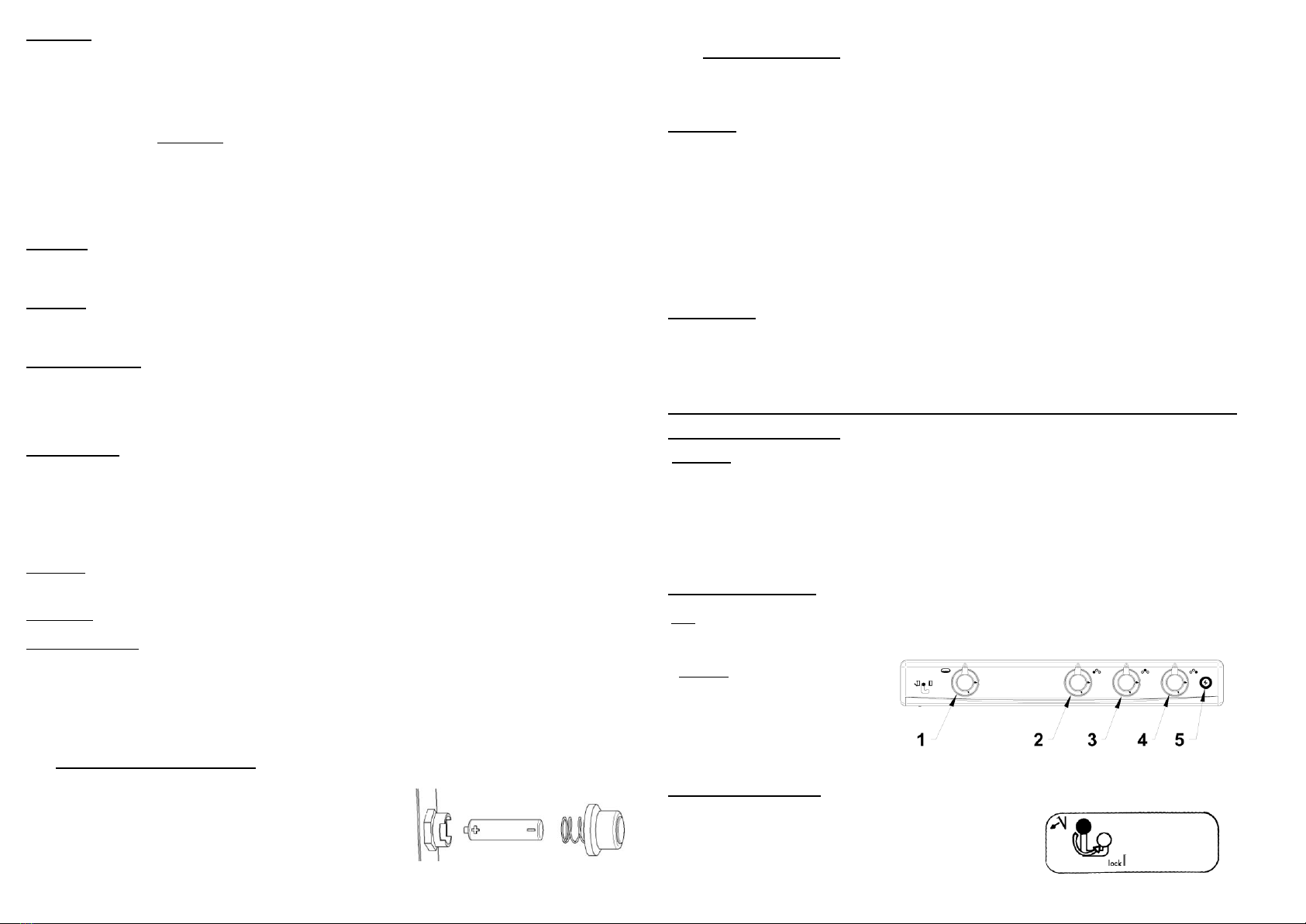
VI –HOW TO REPLACE BATTERY (electronic ignition device)
- Unscrew battery support cap –at the back of the appliance –in an
anti-clockwise direction, insert a 1.5 V battery (R6 type) observing
the correct polarity.
- Re-assemble by proceeding in the reverse order.
- If you do not use your appliance for a long period, remove battery.
VII –BURNERS IGNITION
Each burner is controlled by a tap with control knob. The indicator on the knob indicates tap position. A symbol on the
fascia panel indicates the burner position.
Top Burners
–To light a top burner, depress and turn the respective control knob to the left until the large flame symbol on the knob
coincides with the mark on the fascia panel (this denotes the full on position). Press the electronic ignition button (if
fitted), or apply a lighted long match or other lighting device to the burner. Keep the control knob depressed for 10
seconds until the flame failure device is engaged, then release.
If burner is not alight, repeat the operation. Correct setting can be obtained by gradually turning the control knob until
the flame symbols coincide with the indicator on the fascia panel.
To extinguish the burner, turn the control knob to the right to the OFF position where the knob will lock in the OFF
position (as shown on diagram below).
Oven Burner
- The oven is also controlled by a safety flame failure device that shuts off the gas supply in the event of accidental
burner extinction. To light the oven burner, press electronic ignition button if equipped or apply a lighted match or any
other lighting device to the hole in the bottom plate. Turn the control knob until the large flame symbol coincides with
indicator on the fascia and keep depressed for 10 seconds to set the flame failure device, then release. Large flame symbol
denotes full on position, small flame symbol denotes slow position.
Note: the slide out drip tray is not designed for use as a baking dish; its purpose is to catch drips and spills.
Lighting the Grill burner:
Important: Before lighting the grill burner, open the oven door, and pull out the knob heat-shield to the stop.
Turn the knob to the left (clock-wise). Press the electronic ignition button until the burner lights and keep the control
knob depressed for 10 seconds to engage the flame failure device, then release. The grill should now be operating. Close
the door up to the knob heat-shield.
The burner is in the ‘OFF’position when the control knob coincides with the relief point symbol. To light the grill burner,
first open the oven door, pull the knob heat-shield out to the stop, push in and turn the knob to the left. Press the
electronic ignition button and keep the control knob depressed for 10 seconds to engage the flame failure device, then
release. The grill should now be operating. Close the door up to the knob heat-shield.
Using the Grill burner
Position the oven rack at the top level. The grill should be pre-heated for approximately 5 minutes before use.
Note: for toast and other low/flat foods you should use a grill tray or rack to bring your toast up close to the grill. Food
that you want to brown under the grill must be positioned close to the burner by the use of an appropriate grill tray or
other baking dish.
Symbols
1- Oven/Grill control knob
2 - 3 –4 –Top Burners
5 - Electronic ignition button
Oven door locking system
Note: to lock the door, push the control panel lever downwards.

VIII –GAS ADJUSTMENT
JETS AND OUTPUT
Burner
Nominal
output
NGC
Propane 2,75kPa
Watt
Mj/h
Jet size
Input g/h
Large
2500
8.5
80
182
Medium
1750
5.9
67
127
Small
1000
3.0
50
73
"Enamelled" oven
1700
5.7
69
131
"S.Steel" oven
1500
4.8
60
109
Grill
1350
4.4
58
98
Air ring adjustment on oven burner
How to remove the "U"-shaped burner:
-Unscrew the fixing screw placed in front of the thermocouple.
-Remove thermocouple fixing screw
-Remove oven burner and adjust according to drawing.
IX –UTILISATION
VENTILATION
Operating a gas cooking appliance brings about heat and damp exhaust in the room where it is being operated. Always
make sure that the room is properly ventilated: keep natural aeration apertures opened or install a mechanical aeration
device (hood). Intensive and prolonged operation can require extra aeration (by opening a window) or by providing a
more efficient aeration (hood - if any - on full on position).
HOW TO CHOOSE COOKING USTENSILS
The pan diameter should be suitable for the burner output to avoid any useless energy consumption.
-Use Ø 120 mm diameter pans with the small burner (1000 W)
-Ø 120 to 200 mm diameter pans with the small burner (1750 W)
-Ø 180 to 260 mm diameter pans with the large burner (2500 W).
X –MAINTENANCE INSTRUCTIONS
Do not use any abrasive cleaner. In the event of overflowing, use a wooden spatula.
Clean up spillage of acidic liquids immediately i.e. lemon juice, vinegar, etc...
On the very first operation, the stainless steel upper grid and oven bottom plate can
yellow a little bit.
For an easy cleaning of the upper part, lift the grid (see drawing). To clean it,
unlock the pan-holders by unscrewing the fixing screws and push the holders to the
right or to the left.
Grid, burner caps and cups can be removed and cleaned with appropriate cleaners
knowing that cups are made of aluminium. Dry carefully before reassembling and
make sure every part is correctly reset. While operating, the flame is considered as
correct when the tongue is blue. If the tongue is yellow, it is essential to check that
every single burner part is properly reset. Anomalies can arise from bad
positioning.
Note: The Inside glass of the oven can be removed for cleaning by removing
the small screws holding the two brackets on and care fully sliding the glass
down until it clears the top bracket: reverse these steps to reassemble.
ABNORMAL OPERATION
While operating, the flame should be mostly blue.
Check that burner parts are correctly repositioned after cleaning and if abnormal operation
persists have the appliance serviced by a qualified person.
ANY OF THE FOLLOWING ARE CONSIDERED TO BE ABNORMAL OPERATION:
Yellow tipping of the burner flame.
Sooting up of cooking pots, pans etc.
Burners not igniting properly.
Burners failing to remain alight.
Burners extinguished by drafts.
Gas valves that are difficult to turn.
FOR WARRANTY SERVICE AND PARTS CONTACT:
Ocean Solutions International
Telephone: (07) 3807 6033
Fax: (07) 3807 6055
Email: service@oceansolutions.com.au
Unit 11 / 65 Business Street
YATALA, QLD 4207
Oven burner ring
Air-adjustment
Adjust to 5 mm for
Propane 2.75 kPar
Diagram: cleaning
This manual suits for next models
7
Other Eno Cooker manuals


