Euroclima ZHK NANO User manual

=+.1$12
,16758&7,210$18$/

instruction and operation manual ZHK NANO
V04-18 1 / 116
In addition to the instructions in this guide,
subject-specific standards, as well as local, national and
international regulations must be observed.
!
Please give this instruction manual after com-
pletion of the work to the operating staff of the
AHU. Please keep the complete instruction and
operating manual at your documents.
!
ĞƚƌŝĞďƐĂŶůĞŝƚƵŶŐ
/ŶƐƚƌƵĐƚŝŽŶŵĂŶƵĂů
DĂŶƵĂůĞĚŝƐƚƌƵnjŝŽŶĞ
ET 174-0

instruction and operation manual ZHK NANO
34 / 116 V04-18
Attention: For soft bags the lower bags of the filter cells are to lift up in order to
prevent damage with the clamping system (Figure 60)!
Figure 60: Lifting the filter bags
Attention: If different widths of filter are planned for one filter frame with clamp-
ing mechanism, then the order of the insertion have to be according the filter
frame raster (see figure beneath). Otherwise it leads to an air bypass.
Figure 61: filter frame for different filter
sizes
Figure 62: consider the order accord-
ing the filter frame raster
Figure 63: filter section with in-
serted filters
Attention: Filters must be pushed completely to the back, so that all filters all
around fit closely to the filter frame and an air bypass is avoided. For checking
purposes, examine if the first filter fits closely to the sealing. (Figure 65)

instruction and operation manual ZHK NANO
V04-18 35 / 116
Figure 64: pushing and clamping of the fil-
ters to the rear wall
Figure 65: check, if filter lie on the sealing
6 Installation
6.1 Heat exchanger connection
6.1.1 General notes
Before connecting the heat exchanger, the piping system must be rinsed thoroughly.
An absolutely stress-free connection has to be ensured and the transmission of
vibrations and longitudinal expansion between the device and the piping system
must be safely prevented.
In order to avoid corrosion due to water, the requirements regarding water qual-
ity, professional installation, commissioning and maintenance of VDI 2035 sheet
2 have to be complied.
Connection pipes with thread:
To prevent damage of the heat exchanger connection, it is necessary to hold against with a pipe
wrench during the screwing (Figure 66).
Figure 66: Holding against with a pipe wrench

instruction and operation manual ZHK NANO
36 / 116 V04-18
Recommended sealing material for threaded sleeves:
-Water / glycol heat exchangers, use Teflon tape.
In these cases, hemp cannot be used as sealing material!
Connection pipes without thread:
If the connection pipes are executed without threads, then a mechanical, force-fitting connection
(STRAUB coupling) is recommended (Figure 69). This coupling could be included optionally in the
scope of delivery of EUROCLIMA, if not, then it must be provided on site. In order to avoid a dam-
age of the copper pipe of the heat exchanger due to mechanical force, a ring is used to reinforce
the copper pipe (Figure 67 and Figure 68).
Figure 67: copper pipe with reinforcing ring
Figure 68: copper pipe with inserted reinforc-
ing ring
Figure 69: STRAUB coupling
Figure 70: mounted STRAUB coupling
Other types of connection, e.g. welding or soldering are not recommended by EUROCLIMA, be-
cause of risk of fire of neighboring materials. If one of those type of connection is chosen, the act-
ing assembler carries the responsibility.
The piping of the heat exchanger should hinder a for maintenance required expansion of the heat
exchanger as less as possible.
The connection of the heat exchanger is to execute as indicated on the label on the AHU (connec-
tion diagrams in Figure 71).

instruction and operation manual ZHK NANO
V04-18 37 / 116
Figure 71: Heat exchanger connection
The heat exchanger operates according to the cross-counter-flow principle. Only preheat can be
supplied for parallel flow operation on request.
1. All standard heating and cooling heat exchangers - counter flow
2. Preheat heat exchanger (freezing risk - on request) - parallel flow
Hydraulic connection schemes of heating or cooling coil should be carried out as shown in the
scheme Figure 72 with a three way valve as a mixing valve. Compared with a flow control using a
straight-through valve this connection avoids unequal temperature profiles, in that way air heating
or cooling is quite uniform along the coil surface.
Figure 72: Hydraulic connection scheme
To vent and drain the heat exchanger connection, valves are mounted (on request). To ensure cor-
rect operation must be ensured, however, that the vent is on the highest point of the whole water
cycle and the drain at the lowest. Otherwise, the valves shall be mounted on another suitable point
in the circuit.

instruction and operation manual ZHK NANO
38 / 116 V04-18
Figure 73: Drain valve
Figure 74: Vent valve
6.2 Drain for condensate and excess water
Each drain must be equipped with a siphon. Siphons are available as accessories from EURO-
CLIMA.
6.2.1 Standard siphons
A space-saving design of the necessary siphon height we can do on request. Contact your sales
representative for detailed information.
The following conditions are essential for correct operation:
-At each drain a siphon must be connected.
-Several drains may not be connected to one siphon.
-The water from the siphon must run in a funnel.
-Before starting, fill the siphon with water.
-In case of outdoor units an antifreeze mechanism has to be provided on site.
The heights H1, H2 and H3 can be determined from the maximum negative pressure (p) and maxi-
mum pressure (p) in the section of the siphon or be determined by the information on the technical
data sheet as follows:
Total pressure pges = 1196 Pa
Dynamic pressure pdyn = 83 Pa
Total static pressure pstat = pges ±pdyn = 1113 Pa
1 mmWS = 9,81 Pa
H1 > 1113/9,81 = 114 mm + 15 mm (Safety) = about 130 mm
H2 = 65 mm
Siphon on suction side (in direction of airflow before the fan), see Figure 75.
H1 (mm) > p (mm WS)
H2 (mm) > p/2 (mm WS)

instruction and operation manual ZHK NANO
V04-18 39 / 116
Figure 75: Siphon on suction side
Siphon on pressure side (in direction of airflow after the fan), see Figure 76.
H3 (mm) > p (mm WS)
H4 (mm) t0
Figure 76: Siphon on pressure side
6.2.2 Ball siphons
If ball siphons with the below shown design are included in the delivery from EUROCLIMA, then
the following items should be observed during installation:
Depending on the suction side or pressure side mounting position, the siphon body has to be in-
stalled so that the direction of the arrow (see Figure 77) corresponds to the flow direction.
- Pa = suction side
+ Pa = pressure side
Figure 77: Observe the mounting position - flow direction according to the arrow

instruction and operation manual ZHK NANO
40 / 116 V04-18
Siphon on suction side (in direction of airflow before the fan)
Figure 78: Suction side execution
Siphon on pressure side (in direction of airflow after the fan)
The black plug must be removed for the pressure side installation (see Figure 80).
Figure 79: Pressure side execution

instruction and operation manual ZHK NANO
V04-18 41 / 116
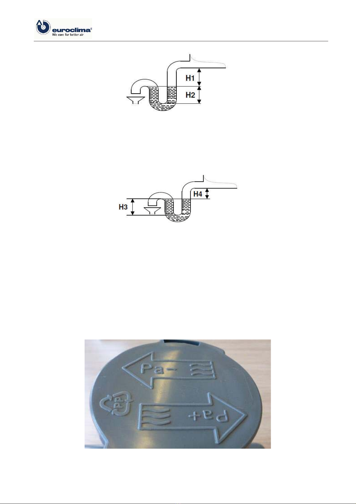
Figure 80: Pressure side installation: remove the black closing plug
6.3 Duct connection ±airside connection to AHU
Depending on the customer's requirements, EUROCLIMA devices are equipped with various ac-
cessories and options for attaching air duct elements like dampers, flexible connections, frames,
panel flanges, etc.
If no such accessories are included in the scope of delivery, then the airside mounting of compo-
nents of the duct system is made directly to the housing of the AHU. Depending on the device
opening, this can be done directly on the panel flange or directly on the external panel of the de-
vice.
When connecting, make sure that the requirements listed below are followed.
Requirements
-Ensure proper performance of the AHU by avoiding of excessive pressure drops in the duct. To
minimize the noise, the basic rules of the duct construction and acoustic design shall be ob-
served.
-A suitable seal (not included in the scope of supply) has to be installed between the device
housing and the component of the duct system.
-The aero-technical connections must be executed tension and torsion free, i.e. no forces /
loads are allowed to be transmitted to the device housing by means of attached accessories
such as ducts etc. The components on the system side must be fastened and supported sepa-
rately.
-Even if no flexible connection is included in the scope of delivery of the device, an elastic con-
nection must always be installed to prevent structure-borne sound transmission between the
device and the duct system. It is recommended to use an interposed elastic connection of at
least 140 mm in width, which shall be installed unstrained between the duct and the AHU.
-This elastic connection must have a sufficient flexibility and must be installed in a professional
manner in order to avoid transmission of vibrations to the duct system.
-For a proper performance of the AHUs the observance of the basic rules of the duct construc-
tion is necessary. By appropriate planning, dimensioning and execution of the duct system, in-
creased pressure losses and flow noise in the duct are avoided.

instruction and operation manual ZHK NANO
42 / 116 V04-18
Number of screws
The duct component are screwed as follows,
-each at a distance of 120 mm from the corner
-additional number of screws see Table 3 and Figure 81.
Table 3: Information on the screw distances
Length or width
Additional number of
screws
< 915
0
>= 915 <= 1220
2
>= 1372,5 <= 1830
3
>= 1982,5 <= 2592,5
4
> 2745 <= 3202,5
5
>= 3355 <= 3660
6
> 3812,5 <= 3965
7
Figure 81: Information on the screw distance
6.3.1 Insulation of fresh air damper
Before connecting the duct section, the flange of the fresh air damper must be insulated in the
course of the fresh air duct insulation on site. This action is urgently required to prevent the for-
mation of condensation by heat transfer.
If fresh air dampers are not integrated in the AHU casing, then also the damper frame must be in-
sulated.

instruction and operation manual ZHK NANO
V04-18 43 / 116
7 Electrical connection
-The electrical connection must be executed in compliance with international regulations such
as the Low Voltage Directive and the requirements of electromagnetic compatibility of national
legislation and the requirements of the local electricity provider.
-All electrical connections must be inspected annually and deficiencies (for example, loose ca-
ble strands, loose screw and clamp connection,...) must be eliminated immediately.
7.1 Connecting to an external protective conductor system
The AHU must be connected to an external protective conductor system. The AHU shall be either:
-connected at the base frames or
-alternatively, at the potential compensation, that is mounted on the flexible connection by EU-
ROCLIMA.
Furthermore, each electrical component must be connected to the protective conductor system.
The connection to the external protective earth system has to be executed according to EN 60204-
1, pt. 5.2. The minimum cross-sectional-surface of the earth at frequency converter has to be
10 mm², otherwise 4 mm² at units with control. Depending on the cross-sectional-surface of the
outer conductor, the requirements regarding minimum cross-sectional-surfaces of the protective
earth system according to EN 60204-1, pt. 5.2, table 1 have to be considered additionally.
After assembling and installation the consistency of the protective conductor system has to be
checked and documented according to EN 60201-1, pt. 18.2.
Correct direction of motor rotation is a result of direction of fan impeller rotation which is signed by
an arrow: for EC fan refer to Figure 82.
Before connecting the motor check the rotating field of mains connection with a suitable device. Af-
terwards, connect the phases accordingly to repair switch.
Figure 82: Rotation marking of EC
fans
Fastening torque for electrical connections on the control panel refer to Table 4:
Thread
Ø
M4
M5
M6
Nm
min.
0,8
1,8
2,7
max.
1,2
2,5
4
Table 4: Torques for the motor terminal board

instruction and operation manual ZHK NANO
44 / 116 V04-18
Before connecting to the local power network, must be controlled, that the local
power supply coincides with the motor requirements from the nameplate. In gen-
eral the fan motors are designed for continuous operation. Abnormal operating
conditions, particularly multiple start-ups at short intervals should be avoided,
they may lead to thermal overloading of the motor.
7.2 EC motors
EC motors are variable through an integrated frequency converter. For operation, the supply volt-
age, a digital enable signal and an analog control signal are required for the speed control.
When using residual current circuit breakers (RCDs), the supply line must be protected by means
of a pulsed current (type A) or an all-current sensitive (type B) residual current circuit breaker.
Cable type for motor connection
A shielded cable must be used for the motor cable (supply voltage) and the analog input signal,
and the shield must be grounded on both ends (repair switch & motor).
7.3 Repair switch (emergency stop switch)
According to the standards IEC / EN 60204 and VDE 0113, all hazardous facilities have to be
equipped with a main switch which separates the plant from all active conductors of the main sup-
ply. This means that every single AHU must be equipped with such a repair switch.
Requirements according to DIN VDE 0660 and IEC 947-3 on a repair switch in RED-YELLOW
execution:
1. Is used as a repair, maintenance or safety switch, because the actuation of the switch does not
reset the control commands from control system.
2. Has clearly marked OFF (0) and ON (I) position.
3. In OFF position lockable, to secure against unauthorized or unintentional restart.
4. For outdoor installation the repair switch at least must be IP65.
5. Interrupts the power supply to the AHU (lighting can be excluded, refer to chapter 7.6 (Light-
ing)).
6. Separates the electrical equipment from the main supply.
7. Is easily accessible
8. Mounted within sight of the AHU.
9. The assignment to the AHU can be clearly seen.
10. Emergency stop function: The emergency stop function, which is signaled by the red handle
with yellow background, has to be implemented by additional components in control sys-
tem. Reset means that a manual start command ±separate from repair switch ±must be acti-
vated.

instruction and operation manual ZHK NANO
V04-18 45 / 116
Figure 83: Repair switch
-Control box is equipped with repair switch in execution RED-YELLOW as specified above
-On responsibility of the client must be ensured that of the above specified Requirements ac-
cording to DIN VDE 0660 and IEC 947-3 on a repair switch in RED-YELLOW execution
are fulfilled
a) items 7 to 9
b) item 10, implementation of emergency stop function in control system
7.4 Electric heaters
An electric heater is designed to heat the airflow, which is stated on the technical data sheet, from
the specified air inlet temperature to the air outlet temperature. EUROCLIMA provides electric
heaters with one or more stages according to customer requirements.
The control of the electric heater provided by the customer can be carried out in several ways:
-On-Off at single-stage electric heater (this type of control decreases the lifetime of the electric
heater under circumstances significantly)
-On-Off at multistage electric heater
-Continuous (e.g. with suitable thyristor control)
Fire risk!
With electric heater in operation, the heating elements may arrive to a tempera-
ture of several hundred °C.
In case of malfunction ±heater in operation without adequate airflow ±inadmissi-
ble temperatures may occur. Plastic parts as for example filters, gaskets, droplet
eliminators etc. close to electric heater may become damaged or even catch fire.
Subsequent damages up to fire spread to the building are possible.
In order to avoid the above mentioned risks EUROCLIMA provides as a standard electric heaters
with 2 independent safety thermostats.
7.4.1 AHUs equipped from EUROCLIMA with control
Units, which are supplied from EUROCLIMA with control, are limiting the supply air temperature to
a default value of 35 °C.
The execution and function as specified below is included in the EUROCLIMA delivery.
Control-side limitation of the air temperature after the electric heater

instruction and operation manual ZHK NANO
46 / 116 V04-18
The control of the electric heater always takes place in such a way, that the air temperature after
the electric heater never exceeds the permitted air temperature in the unit (40 °C, if not differently
specified in the technical data). This item must be especially observed, when the air handling unit
is only operated with a partial air flow (e.g. in times of reduced use of the building).
As the heat output of an electric heater is provided very quickly and with ON-
OFF operation in the full amount, arises a significant risk of overheating the unit,
which results in damaging several components, especially when the unit is oper-
ated with low airflows.
For this purpose, the air handling is equipped with a supply air sensor, which directly measures
and monitors the air temperature generated by the electric heater. The control engineering is used
to ensure that the heating power of the electric heater is controlled so, that the temperature re-
mains within the permitted air temperature in the unit.
Avoid overheating of AHU components by residual heat of electric heater
In order to avoid excessive heating of components by residual heat of electric heater control en-
sures that fan motor keeps on running for at least 5 min after cut off of electric heater! By the use
of an enabling contact (see Figure 87) the control engineering also ensures, that the electric
heater can only start its operation when the fan is running.
If in case of main power failure (for example lightning stroke) this automatic run
cannot be ensured, AHU may become damaged by the residual heat of electric
heater.
In order to avoid damages, an uninterrupted power supply is recommended. If AHU is not operated
by an uninterrupted power supply after every main power failure an AHU inspection is requested
as indicated in chapter 9 (Maintenance).
Safety concept
Electric heater power supply is equipped with 2 contactors in serial connection!
The 2 safety thermostats are connected such to protect the AHU both, by contactors in power sup-
ply and by software of control. In case of failure contactors must immediately cut off electric heater
from power supply
-The 2 safety thermostats are connected in serial connection
-The 2 safety thermostats are equipped with manual reset.
-After triggering the reason for stopping must be detected and eliminated before reset of the
thermostat!
Thermostat 1 (Figure 84 and Figure 85)
-Position of thermostat body: fastened on electric heater at connection side, accessible by re-
moving the electric heater access panel.
-Triggering temperature: pre-set ±value must not be changed.
-Sensor position: between heating bars.
-Function: alarm stop in case of over temperature because of low airflow.

instruction and operation manual ZHK NANO
V04-18 47 / 116
Figure 84: Thermostat with
cover cap on the reset button
Figure 85: Thermostat with
uncovered reset button
Thermostat 2 (Figure 86)
-Position of thermostat casing: fastened on outside panel of AHU casing
-Triggering temperature: set to 70 °C ±value must not be changed
-Sensor position: downstream of electric heater in upper area of airflow
-Function: alarm stop in case of over temperature because of missing airflow
Figure 86: Thermostat 2
Connection box may reach high temperatures. For connection use heat-resistant cables (admissi-
ble operation temperature min. 110 °C), for example silicone, Teflon or glass fiber insulated cables.
Cover cap on reset button
Reset button

instruction and operation manual ZHK NANO
48 / 116 V04-18
Connection scheme for electric heater according to EUROCLIMA:
Figure 87: Connection scheme for electric heater
In case of dehumidification wheel downstream of electric heater, it is ensured that control rotates
the wheel while electric heater is on (additional enabling contact).
7.5 Frost protection for plate heat exchanger
At low temperatures and high air speeds, the condensate in the plate heat exchanger can freeze
and cause its icing.
For devices supplied by EUROCLIMA with control, this is prevented by a pressure monitoring of the
plate heat exchanger and the temporary adjustment of the supply air volume flow.
7.6 Lighting
Depending on the number of delivered (optional) lamps, the assignment of the switches and junction
boxes can be found below:
1 Lamp 1 switch
> 1 <= 4 Lamp 1 switch, 1 junction box
> 4 <= 8 Lamp 1 switch, 2 junction box
> 8 <= 12 Lamp 1 switch, 3 junction box
The lamps are mounted and supplied with one side connected and one side loose cables, with a
sufficient length to be routed to the nearest junction box or the next switch.
The AHU will be delivered in parts, and for this reason the lights have to be connected on site in full
responsibility of the client.
If the AHU will be equipped on site with lights, it is to make sure that wet sections (and air down-
stream), such as«
-sections with condensate, such as cooling sections
Lighting with an at least protection of IP55 were used.
Enabling contact:
Fan is running

instruction and operation manual ZHK NANO
V04-18 49 / 116
Switches or junction boxes mounted on the outside of rooftop units must also have at least protection
class IP55.
For units with integrated control and lighting, an additional power supply for the lighting must be
provided and separated from the power supply for the control cabinet. This ensures that the light
also can be switched on during repair work, despite repair switch is switched off (prerequisite for
access to the AHU).
8 Commissioning
8.1 Preliminary steps
-Clean thoroughly the AHU and all components of dust, swarf and other debris.
-Remove all loose parts like tools, etc. and documentation from the unit. Such parts can be
sucked in by the fan and lead to its destruction.
-check all bolt connections and electrical connections and retighten if necessary
-Ensure that the duct pressure corresponds to the pressure for the nominal air flow and the
pressure specified in the technical data sheet.
-Ensure that all planned filters are mounted. Not mounted filters can overload the fan motor.
-All cables must be checked for damage to the insulation and replaced if necessary.
Here are given some points, which could cause problems after transport or not appropriate unit
handling.
-Rotate the impeller of the fan by hand, to check whether it rotates freely.
-Check the motor connection and the matching of the supply voltage at the rated voltage - a
fluctuation of supply voltage between + -5% is permitted.

instruction and operation manual ZHK NANO
50 / 116 V04-18
8.1.1 Airflow measurement by differential pressure measurement at the fan
The delivered airflow rate can be calculated or displayed from the measured differential pressure.
A so-called K-value and an associated formula are used for calculation or for input into display or
control devices.
Usually, two different formulas and thus two different K-values are in use:
Formula A
Formula B
In this formula, the respective air density at
the fan is taken into account.
In this formula, a variable air density is not taken into
account.
The air density must be determined as a
function of air temperature, air humidity, sea
level and atmospheric pressure.
Instead, a "fixed" air density of 1.20 kg/m3is as-
sumed.
With the following formulas, the airflow rate can be determined from the pressure signal:
-Airflow rate calculation -Airflow rate calculation
9
ռ
Nominal airflow rate
m³/h
9
ռ
Nominal airflow rate
m³/h
KA
KA±factor for formula A
m²*s/h
kB
kB±factor for formula B
m³/(h*Pa0,5)
ǻSw
Measured diff. pressure
Pa
ǻSw
Measured diff. pressure
Pa
ȡV
Air density at the fan
kg/m³
If several fans in a fan section are operated in parallel with the same speed, then the total airflow
rate is accordingly a multiple of the calculated individual airflow rate.
:LWKWKHIROORZLQJIRUP ODVWKHVHWSRLQWǻSwcan be determined for a certain airflow rate (e.g. for di-
mensioning a pressure sensor, for constant airflow rate control):
-Target differential pressure calculation
¨Sw.set
Target differential pressure
Pa
ǻpw.set
Target differential pressure
Pa
9
ռ
Target airflow rate
m³/h
9
ռ
Target airflow rate
m³/h
KA
KA±factor for formula A (s.a.)
m²*s/h
kB
kB±factor for formula B (s.a.)
m³/(h*Pa0,5)
ȡV
Air density at the fan (Nomi-
nal value)
kg/m³
Table 5: Formulas for airflow rate measurement
The corresponding K-factors of the fan are shown in the fan-motor data sheet or on the technical
data sheet for the air handling unit. The data on the data sheet always refers to one fan.
The air density at the measuring point is to set up manually, depending on sea level, temperature
and humidity. In most cases, 1.2 kg/m³ is a suitable value.
For AHUs supplied by EUROCLIMA with control, the airflow rate sensors are already preset.
ܸሶൌܭήඨʹήο௪
ߩ
ܸሶൌ݇ήඥοௐ
ο௪Ǥ௦௧ ൌܸሶଶήߩ
ܭଶήʹ
ο௪Ǥ௦௧ ൌܸሶଶ
݇
ଶ
Other manuals for ZHK NANO
3
Table of contents
Other Euroclima Air Handler manuals
Popular Air Handler manuals by other brands

Kampmann
Kampmann KaCool HY 600x600 Installation, operation & maintenance manual

Verano
Verano freshAIR+ VWT Installer manual

Kampmann
Kampmann WZA Assembly, installation and operating instructions

iFlow
iFlow iFLH-14000W manual

CIAT
CIAT CLIMACIAT airtop Series instruction manual

Carrier
Carrier 40RUM Series Installation, operation & maintenance manual