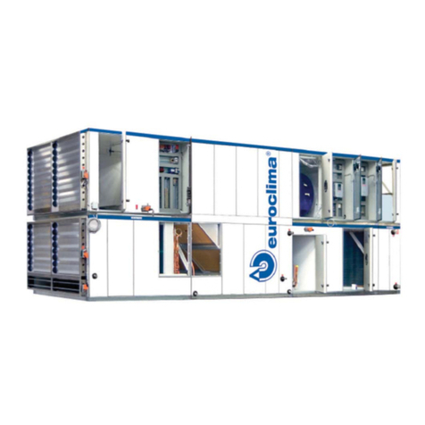
Euroclima ZHK Series User manual

ZHK
INSTRUCTION MANUAL

Instruction Manual ZHK
V07-19.0 1/129
In addition to the instructions in this guide,
subject-specific standards, as well as local, national and
international regulations must be observed.
!
After completion of the work, please give this instruction man-
ual to the operating staff. Please keep the complete instruc-
tion and operating manual filed with your other documents.
!
Betriebsanleitung!
Instruction manual!
Manuale d’istruzione!
ET 174-0

Instruction Manual ZHK
2/129 V07-19.0
Table of contents
1Introduction ............................................................................................................................ 6
1.1 Model code...................................................................................................................... 6
1.2 Intended use / foreseeable misuse.................................................................................. 7
1.2.1 Intended use ........................................................................................................................7
1.2.2 Foreseeable misuse.............................................................................................................8
1.3 Modular design................................................................................................................ 8
1.4 Documentation ................................................................................................................ 8
2Safety instructions / Guidelines to conformity to laws and directives ............................. 10
2.1 CE-conformity / installation instructions for safe operation............................................. 10
2.1.1 CE-conformity / incorporation declaration according to Machinery Directive 2006/42/EC 10
2.1.2 Installation instructions for the proper installation in the building system..........................10
2.2 Indications for minimizing specific hazards .................................................................... 12
2.2.1 General indications ............................................................................................................12
2.2.2 Refrigeration circuit ............................................................................................................14
2.2.3 ATEX AHUs .......................................................................................................................14
2.3 Conformity to laws and directives .................................................................................. 15
2.3.1 General ..............................................................................................................................15
2.4 ErP conformity according to directive (EU) 1253/2014................................................... 15
2.5 Staff selection and qualification ..................................................................................... 16
3Reception control / unloading / transportation to installation site ................................... 16
3.1 Reception control .......................................................................................................... 16
3.2 Lifting by forklift / lift truck .............................................................................................. 18
3.3 Overlifting of AHU sections with crane lugs ................................................................... 19
3.3.1 Control of weight limits of delivery sections .......................................................................20
3.3.2 Necessary actions before lifting delivery sections with crane lugs....................................21
3.3.3 Mounting of crane lugs.......................................................................................................23
3.3.4 Lifting by crane lugs ...........................................................................................................24
3.4 Overlifting of monoblocs ................................................................................................ 25
3.4.1 Weight details for monoblocs.............................................................................................25
3.4.2 Lifting of monoblocs ...........................................................................................................25
3.5 Further necessary actions for the overlifting of both, delivery sections on crane lugs as
well as monoblocs ......................................................................................................... 27
3.6 Storage.......................................................................................................................... 28
4Foundation / erection ........................................................................................................... 29
4.1 Foundation .................................................................................................................... 29
4.2 Erection......................................................................................................................... 30
4.2.1 Potential risks that may arise at the erection site ..............................................................30
4.2.2 Actions to prevent potential risks .......................................................................................31
4.2.3 General indications for the erection ...................................................................................31
4.2.4 Special guidelines for flat AHUs –ceiling AHUs................................................................32
5Assembly .............................................................................................................................. 34
5.1 Assembly of casing........................................................................................................ 34
5.1.1 Actions before the assembly of casing ..............................................................................34
5.1.2 Standard connections and connection components..........................................................37
5.1.3 Detailed solutions and connection components ................................................................39
5.1.4 Establishing the screw connection of AHU parts...............................................................41
5.1.5 Special features for roof AHUs and device separations at wet areas ...............................43
5.1.6 Cable gland........................................................................................................................47
5.1.7 Transport lock ....................................................................................................................48
5.1.8 Securing the position of AHUs...........................................................................................49
5.2 Doors ............................................................................................................................ 49
5.3 Dampers........................................................................................................................ 54
5.4 Airfilters ......................................................................................................................... 54
5.4.1 Panel filter and / or bag filter laterally removable ..............................................................55

Instruction Manual ZHK
V07-19.0 3/129
5.4.2 Panel filter and / or bag filters in filter frame ......................................................................55
5.4.3 Laterally removable bag filters with clamping mechanism ................................................56
5.4.4 HEPA filters........................................................................................................................57
5.4.5 Activated carbon filter ........................................................................................................58
5.5 Dampers with external gear wheels............................................................................... 59
5.6 Hygienic AHUs .............................................................................................................. 59
6Installation ............................................................................................................................ 60
6.1 Heat exchanger connection........................................................................................... 60
6.1.1 General notes ....................................................................................................................60
6.1.2 Steam heat exchanger.......................................................................................................62
6.1.3 Plate heat exchangers for refrigeration circuits .................................................................63
6.2 Humidifier, indirect adiabatic cooling ............................................................................. 64
6.2.1 Water quality ......................................................................................................................64
6.2.2 Protection of the drinking water against pollution ..............................................................64
6.2.3 Special indications for different humidification systems ....................................................65
Spray humidifier –Installation of the pump circuit .......................................................... 65
Evaporative humidifier .................................................................................................... 69
High pressure spray humidifier ....................................................................................... 69
Steam humidifier............................................................................................................. 69
6.2.4 Connection of indirect adiabatic cooling ............................................................................69
6.3 Drain for condensate and excess water......................................................................... 70
6.3.1 Standard siphons ...............................................................................................................70
6.3.2 Ball siphons........................................................................................................................71
6.4 Duct connection –airside connection to AHU................................................................ 73
6.4.1 Insulation of fresh air damper ............................................................................................76
6.5 Pumps........................................................................................................................... 76
6.6 Freeze protection measures .......................................................................................... 76
7Electrical connection............................................................................................................ 77
7.1 Connecting to an external protective conductor system................................................. 77
7.2 AC motors ..................................................................................................................... 77
7.3 EC motors ..................................................................................................................... 82
7.4 Main switch (emergency stop switch) ............................................................................ 82
7.5 Variable, frequency-controlled drives (VFD, frequency converters) ............................... 83
7.6 Electric heaters.............................................................................................................. 83
7.6.1 AHUs equipped from EUROCLIMA with control................................................................84
7.6.2 AHUs which are not equipped from EUROCLIMA with control .........................................86
7.7 Differential pressure restriction for plate heat exchangers ............................................. 86
7.7.1 General indications ............................................................................................................86
7.7.2 Prevention measures .........................................................................................................87
7.7.3 Pressure monitoring with differential pressure switch .......................................................87
7.8 Frost protection for plate heat exchanger ...................................................................... 89
7.9 Lighting.......................................................................................................................... 89
7.10 UV section..................................................................................................................... 90
8Commissioning..................................................................................................................... 90
8.1 Preliminary steps........................................................................................................... 90
8.1.1 Variable frequency controlled drives (frequency converter) - parameters.........................91
8.1.2 Airflow measurement by differential pressure measurement at the fan ............................93
8.1.3 Heat exchanger..................................................................................................................94
8.1.4 Electric heater ....................................................................................................................95
8.1.5 Air filters .............................................................................................................................95
8.1.6 Humidifier / Air washer.......................................................................................................95
General indications......................................................................................................... 95
Spray humidifier.............................................................................................................. 96
Evaporative humidifier .................................................................................................... 96
High pressure spray humidifier ....................................................................................... 96
Steam Humidifier ............................................................................................................ 96
8.2 Refrigeration circuit........................................................................................................ 97
8.2.1 General notes ....................................................................................................................97

Instruction Manual ZHK
4/129 V07-19.0
8.2.2 Manually starting the compressor via EUROCLIMA control system .................................97
8.2.3 Refrigerant .........................................................................................................................97
8.2.4 Compressor lubricant.........................................................................................................97
8.3 Test run......................................................................................................................... 98
8.3.1 Adjusting variable pullies ...................................................................................................98
8.3.2 Resonance at fans .............................................................................................................99
9Maintenance........................................................................................................................ 100
9.1 Electrical connection, control cabinet........................................................................... 101
9.2 Fan / motor group........................................................................................................ 101
9.2.1 Fan...................................................................................................................................101
9.2.2 Motor................................................................................................................................103
9.2.3 V-belt drive.......................................................................................................................103
9.2.4 Re-tensioning of belts ......................................................................................................104
9.2.5 Replacing of belts ............................................................................................................106
9.3 Air filters ...................................................................................................................... 107
9.3.1 Panel filters ......................................................................................................................108
9.3.2 Bag filters .........................................................................................................................108
9.3.3 HEPA filters......................................................................................................................108
9.3.4 Activated carbon filters.....................................................................................................108
9.4 Heat exchangers ......................................................................................................... 108
9.4.1 Medium water / steam......................................................................................................108
9.4.2 Refrigerant .......................................................................................................................109
9.4.3 Electric Heater .................................................................................................................109
9.5 Humidifiers .................................................................................................................. 109
9.5.1 General indications ..........................................................................................................109
9.5.2 Spray humidifier ...............................................................................................................110
9.5.3 Evaporative humidifiers....................................................................................................110
9.5.4 High pressure humidifiers ................................................................................................110
9.5.5 Steam humidifiers ............................................................................................................111
9.6 UV section................................................................................................................... 111
9.7 Dampers...................................................................................................................... 111
9.8 Sound attenuators ....................................................................................................... 111
9.9 Weather louver............................................................................................................ 111
9.10 Energy recovery systems ............................................................................................ 111
9.10.1 Plate heat exchangers .....................................................................................................111
9.10.2 Heat wheels .....................................................................................................................112
9.10.3 Heat pipes........................................................................................................................112
9.10.4 Accublocs.........................................................................................................................112
9.11 Refrigeration circuit...................................................................................................... 113
9.11.1 Leakage checks...............................................................................................................113
9.11.2 Maintenance ....................................................................................................................114
9.11.3 Inspection.........................................................................................................................115
9.12 Hygienic AHUs ............................................................................................................ 116
9.13 Maintenance plan ........................................................................................................ 116
10 Information on airborne noise emitted by the AHUs - on request .................................. 118
11 ATEX AHUs ......................................................................................................................... 118
11.1 General notes.............................................................................................................. 118
11.2 Information regarding the unit, protective systems and components............................ 120
11.3 Information for erection, assembly, commissioning, maintenance and repair............... 121
11.3.1 Foundation and erection ..................................................................................................121
11.3.2 Assembly, connection ......................................................................................................121
11.3.3 Fan section ......................................................................................................................121
11.3.4 Air filters ...........................................................................................................................122
11.3.5 Heat exchangers / steam humidifiers ..............................................................................122
11.3.6 Field devices ....................................................................................................................122
11.3.7 Declaration of conformity .................................................................................................122

Instruction Manual ZHK
V07-19.0 5/129
12 Disassembly and disposal................................................................................................. 123
12.1 Disassembly................................................................................................................ 123
12.2 Disposal ...................................................................................................................... 124
Figure index .............................................................................................................................. 125
Table index................................................................................................................................ 129
-Original Instructions -

Instruction Manual ZHK
6/129 V07-19.0
1 Introduction
This is the instruction and operation manual for an air handling unit, hereinafter designated as
‘AHU’.
1.1 Model code
ZHK INOVA S 15/6 –15/6
AHU type (standard)
AHU execution
AHU size supply air
AHU size exhaust air
Legend used for AHU type
ZHK INOVA
casing type with thermal separation profile
ZHK 2000
casing type without thermal separation profile
ZHK NANO
compact AHU series
ETA XXX
key ETA: including control
ETA XXX COOL
including refrigeration circuit
ETA MATIC
standard
ETA POOL SPA
compact AHU for pool dehumidification with refrigeration
circuit (option)
ETA POOL OLYMPIC
for pool dehumidification including plate heat exchanger
and refrigeration circuit
ETA PT
heat recovery by plate heat exchanger
ETA ACCU
heat recovery by accumulator
ETA ROT
heat recovery by heat wheel
ETA WP
refrigeration circuit, heat pump function
ETA PAC
indirect adiabatic cooling
CLEANLINE
for hygienic use, including control
Design key AHU execution
S
AHU for indoor installation
DG
AHU for outdoor installation
I
AHU Industrial –heavy version of the panels
HG
AHU hygienic execution
Legend for the AHU size
Example 15/6: the first index (15) corresponds to the clear width, the second index (6) to the clear
height. According to the following table, the dimensions in mm are →15/6 = 1525 x 610 mm (clear
width x clear height)
Index
3
4
6
9
12
15
18
21
24
Dimension (mm)
305
457,5
610
915
1220
1525
1830
2135
2440
Index
27
30
33
36
39
42
45
48
Dimension (mm)
2745
3050
3355
3660
3965
4270
4575
4880

Instruction Manual ZHK
V07-19.0 7/129
This information applies both to the ratios of the supply air and the exhaust air.
1.2 Intended use / foreseeable misuse
1.2.1 Intended use
The AHU is used, depending on the chosen purpose for
-transportation and conditioning of air in and out of buildings, in which humans stay
-creation of a desired room air quality in the occupied area of humans
-creation of an acceptable comfort or desired working conditions
-depending on the AHU type, the air conditioning is done primarily by
oAir change
oControl of air temperature and air humidity
oFiltration of normal polluted air
oFiltration at specific requirements (clean room and so on)
The AHU is suitable for
-operation in the range of the agreed design data
-an ambient air temperature range of –20 °C to + 60 °C at installation site, if electrical/electronic
components are mounted on the outside of the AHU, then + 40 °C maximum
-a minimum temperature of the transported air of -20 °C (if necessary, freeze protection
measures must be installed)
-a maximum temperature of the transported air of +60 °C
-inside the AHU at motors and other electrical/electronic components up to +40 °C maximum
The operation at other conditions must be agreed in writing. Unless otherwise agreed, the design
of the AHU is for a nominal density of the air of 1,20 kg/m³.
Design responsibility for AHUs, are built according to customer specifications
AHUs of the series ZHK 2000 and ZHK INOVA, as described in this manual are designed, built and
delivered according to customer requirements. Therefore, EUROCLIMA can select and offer a
number of materials and components, which are varied in quality levels.
Generally, a HVAC specialist, knowing the exact application of the AHU, generates a specification,
in which customer requirements for the AHU are defined. The properties of the AHU, specified by
EUROCLIMA, are agreed with the customer and are stated on the technical data sheets and draw-
ing of the AHU.
Thus, the assessment of the suitability of the AHU for the specific application (e.g. used materials
or filter classes) is not the responsibility of EUROCLIMA. Therefore, a disclaimer applies for EU-
ROCLIMA, if the suitability of the AHU for the specific application and installation site should not be
fully stipulated.
As an example, the use at highly polluted or corrosive air (e.g. close to the sea, in industry atmos-
phere or at contaminated/corrosive exhaust air) is mentioned. In this case, corrosion of the AHU or
inappropriate filtration of the air could be a result of a planning error, for which EUROCLIMA de-
clines the responsibility, because the AHU is built according to the confirmed specifications.

Instruction Manual ZHK
8/129 V07-19.0
Components provided by the customer
If it is planned and agreed, that EUROCLIMA installs components in the AHU, which are provided
by the customer, EUROCLIMA only accepts liability, if there are significant mistakes in construc-
tion.
The warranty for proper functionality of the provided components as well as the component con-
cerned safety requirements is excluded.
For AHUs with components provided by the customer no CE-conformity is generated due to this
reason.
Changes of the AHU by the customer
Attention!
If there are any changes to the AHU undertaken by the costumer after delivery, then the warranty
becomes invalid. Subsequent changes of the AHU, which are not authorized by EUROCLIMA, are
the sole responsibility of the executing person, concerning functionality as well as safety aspects.
1.2.2 Foreseeable misuse
Other than above use, is considered as improper and must be excluded totally:
-The commissioning of equipment, prior to performing the steps indicated in the assembly in-
structions and operating with the fan section door open, is a serious security risk.
-Opening the AHU, without securing the main switch in the off position, represents a massive
security risk.
-The operation of an AHU equipped with an electric heater while the fan-motor is cut off, or if the
fan is working at a limited airflow, for example, caused by closed dampers or similar and with
the electric heater in operation produces an imminent fire risk.
-The operation in an explosive atmosphere is prohibited, as long as the AHU is not executed in
accordance with the ATEX directive. Application of AHUs in ATEX execution, see chapter 11
(ATEX AHUs).
-Handling of air with corrosive / aggressive components.
-Pressure-sided doors can detach suddenly while opening. So, there is a risk of injury for the
user. See chapter 5.2 Doors.
1.3 Modular design
Because of the modular AHU design, the instruction manual covers all the possible sections and
components which can be delivered. The ordered range is smaller and can be seen on the tech-
nical data sheet - see chapter 1.4 (Documentation).
In this manual, treated parts/components that are not part of the delivered AHU, can therefore be
disregarded.
1.4 Documentation
The AHU will be delivered with the following documentation:
Instruction manual ZHK (This document is an
extract of the complete instruction and operating
manual and includes chapters 1 to 4.)
There is a cardboard box for loosely deliv-
ered parts inside of the AHU.
QR-Code for the download of the complete man-
ual
On the AHU and in the delivered manual on
page 1

Instruction Manual ZHK
V07-19.0 9/129
Depending on AHU type and execution, the following documentation is included:
Components operation manual
There is a cardboard box for loosely deliv-
ered parts inside of the AHU.
AHU drawing
applied on each delivery section
Wiring diagram for ETA
in control cabinet
Operation manual control ETA MATIC /
ETA POOL
in control cabinet
Depending on type of accessories, the following documentation is included:
K-value for airflow measurement
glued on the inside of the fan section door
Belt drive and tension data
There is a cardboard box for loosely deliv-
ered parts inside of the AHU.
Data point list
in control cabinet
Piping & instrumentation diagram
in control cabinet
Records for refrigeration circuit application
in control cabinet
The above mentioned documentation must always be available when working on the AHU!
You will also find stickers with warning labels and other instructions on and inside the AHU.
In this manual and on labels used symbols:
Indicate safety instructions –or yellow triangle with the corresponding hazard pic-
togram
Indication to avoid damage
In addition to the contents of this manual, the instruction manuals of the component manufacturers
must be followed. These will be delivered separately or can be downloaded from the homepage of
the component manufacturer. In case of contradiction between this manual and instruction manu-
als of the component manufacturer for safety instructions, the most restrictive interpretation is
valid. At differences between this manual and the instruction manual of the component manufac-
turer, the instruction manual of the component manufacturer has to be applied. In case of doubt,
please contact your EUROCLIMA office.

Instruction Manual ZHK
10/129 V07-19.0
2 Safety instructions / Guidelines to conformity to laws and directives
2.1 CE-conformity / installation instructions for safe operation
2.1.1 CE-conformity / incorporation declaration according to Machinery Directive
2006/42/EC
An AHU (or any part thereof) supplied by EUROCLIMA is by definition of Machinery Directive
2006/42/EC an incomplete machine, because it is limited in function and is only a part of the build-
ing system. Accordingly, for a safe operation before the initial start-up, the general in chapter 2.1.2
(Installation instructions for the proper installation in the building system) and in particular in
the following chapters described on-site work must be carried out for a safe operation.
Depending on the scope of supply, a CE-conformity declaration or a declaration of incorporation
will be issued. A declaration of incorporation will be issued, if supplementary work on site is neces-
sary to gain the CE-conformity. This applies if no frequency converter, which is necessary, or no
filter manometer is included in delivery (see chapter 2.4).
2.1.2 Installation instructions for the proper installation in the building system
For the proper installation of AHU equipment and the safe operation of the system, depending on
the configuration of the AHU, before the first start at least, the following points must be imple-
mented or upgraded and is the responsibility of the client:
Assembly of delivery sections
The delivery sections of the AHU must be assembled and linked together, according to the drawing
supplied on the inner face of fan section door. See the chapter 4 (Foundation / erection).
Secure inlet and outlet openings
All the inlet and outlet openings must be connected to ducts or respectively equipped with grilles,
to prevent persons accessing from the outside to moving parts (such as fan wheels) during opera-
tion.
Main switch
See chapter 7.3 (EC motors).
Installation of ceiling AHUS –flat AHUs
See chapter 4.2.4 (Special guidelines for flat AHUs –ceiling AHUs).
Installation of filters
See chapter 5.4 (Airfilters).
Temperature limitation
Ensure that a control system is fitted and that the AHU is only operated with a supply air tempera-
ture below the allowable maximum (see chapter 1.2.1 Intended use, when not stated otherwise in
the technical data). For this purpose, the continuous monitoring of the supply air must be ensured
on site.
Measures regarding noise attenuation
As a basis for on-site sound measures calculation (such as for sound attenuators) the on request
available sound data can be used. For information regarding the emitted sound power level over
the openings see the technical data sheet, which is available on request –refer to chapter 10
Information on airborne noise emitted by the AHUs - on request).

Instruction Manual ZHK
V07-19.0 11/129
Measures to minimize the risk of water damage or damage caused by similar media
See chapter 4.2.2 (Actions to prevent potential risks).
Motor connection
See chapter 7.2 (AC motors).
Frequency controller for Plug fans
Also, if not supplied by EUROCLIMA, a frequency converter must be installed to reach the calcu-
lated operating point. For details see chapter 7.5 (Variable, frequency-controlled drives (VFD,
frequency converters)).
Connection to an external protective conductor system
See chapter 7.1 (Connecting to an external protective conductor system).
Electric heater
Installation (if not supplied by EUROCLIMA) and connection of thermostats for safety shutdown,
see chapter 7.6 (Electric heaters).
Plate heat exchanger
Installation (if not supplied by EUROCLIMA) and connection of differential pressure switches to
protect the plate heat exchanger from damage in chapter 7.7 (Differential pressure restriction
for plate heat exchangers).
Siphons
Connecting according to chapter 6.3 (Drain for condensate and excess water).
Dampers with external gear wheels
According to chapter 5.5 (Dampers with external gear wheels).
Flexible connection
Installations (if not supplied by EUROCLIMA) refer to chapter 6.4 (Duct connection –airside
connection to AHU).
Heat exchanger
For all heat exchangers which are connected on-site, irrespective of the medium used (water, wa-
ter-glycol mixture, aqueous vapor, refrigerant ...), it must be ensured by the customer that the re-
sulting assembly meets the pressure equipment directive, PED '2014/68 / EU.
Field equipment for roof AHUs
On site mounted field devices for roof AHUs, e.g. damper position motors or pressure switches
must be weather-protected in case of insufficient IP class and - depending on the installation situa-
tion - possibly also protected against icing.
Freeze protection
The customer must ensure sufficient freeze protection measures. See indications in chapters
4.2.1 (Potential risks that may arise at the erection site), 4.2.2 (Actions to prevent potential
risks), 6.6 (Freeze protection measures) and 7.8 (Frost protection for plate heat exchanger).
Venting, draining of heat exchangers
See chapter 8.1.3 (Heat exchanger).

Instruction Manual ZHK
12/129 V07-19.0
2.2 Indications for minimizing specific hazards
2.2.1 General indications
An improperly performed maintenance can pose a security risk!
Risk of thin sheets, when working on AHU
During work on AHU (or on parts), there is a substantial risk of cutting with thin
sheets as e.g. roof sheets, fins of heat exchangers, corners and edges - Use per-
sonal protective equipment: wear protective helmet, gloves, safety shoes and long
protective clothing.
Lighting
For work on AHU (maintenance and inspection work) make sure there is adequate lighting.
Firefighting in case of fire
In general, the local fire protection regulations must be observed.
-If the AHU is part of the smoke extraction concept, then the specifications
of this concept have to be observed.
-Otherwise, the power supply of the AHU must be interrupted immediately
at all conductors. In addition, the dampers must be closed to consequently
prevent oxygen supply and fire spread.
Exposure to harmful substances in case of fire
In case of fire, some materials can produce harmful substances. In addition,
harmful vapors can escape from the AHU. Therefore, severe respiratory protec-
tive equipment is required and the danger zone has to be avoided.
Exposure to rotating parts / hot surfaces / electrocution
When working on and/or in the AHU note the following risks:
Indentation of body parts in moving parts (belt drive, fan impeller, external damper
gear wheels ...).
Burns and scalds on hot AHU components such as heat registers, heat exchang-
ers, ...
Electrocution on current-carrying parts such as electric motors, frequency convert-
ers, electric heaters, control cabinets, interior lighting etc.
Therefore, it must be ensured that prior to working on and/or in the AHU, that…
-all current-carrying parts, such as cable plug connections, fan motors, valves, motors and elec-
tric heaters are disconnected from the power supply by using the main switch (emergency
stop) and that the switch is locked in position 'off' in order to effectively prevent a re-activation

Instruction Manual ZHK
V07-19.0 13/129
during the work. The housing of the AHU interior lighting (can have separate supply) is not cur-
rent-carrying.
-all moving parts, especially the fan wheel, motor and heat wheel have come to a standstill; wait
at least 5 minutes after switching off before opening the doors.
-for maintenance of frequency controlled motors, a waiting time of 15 minutes is recommended –
it gives time to break down the residual capacitive charge of the frequency converter.
-Remove the key from doors with door lock before entering in the casing of the AHU. Keep the
key out of reach of unauthorized persons.
-Check that the hot media supply such as steam is interrupted and all the heat registers, heat
exchangers, etc. are cooled to ambient temperature.
In case of standstill of the plant (e.g. power failure), make sure that the main
switch is always checked. Only when it is in the off position and secured against
unintentional restart, appliance doors can be opened, cable plug connections can
be disconnected and work on the device can be carried out.
Start of the AHU
Ensure after working and before the start that…
-nobody is in the AHU.
-all protective devices are working, (optional safety devices such as the door guard and belt
guard mounted again) and doors equipped with door locks are locked and the keys are re-
moved –refer to chapter 5.2 (Doors).
Storage of potential energy in gases and fluids
All heat exchangers can be operating up to a maximum pressure of 15 bar. If the
fluid is under higher pressures, the safety and tightness cannot be guaranteed.
Preventing the risk of explosion and fire spread
To prevent the fire spreading, fire dampers shall be installed into the ducts be-
tween the fire compartments.
Prevention of exposure caused by antifreeze agents
Avoid body contact with antifreeze agents, because they may cause burns. Al-
ways wear appropriate protective clothing (e.g. gloves, goggles, ...).
In case of fire, avoid the danger zone and meet different safeguards. It is recom-
mended to wear a mouth guard, because of the risk of poisoning by inhaling the
vapors.
Prevention of hazards caused by steam heaters or humidifiers
By hot steam there is a danger of burns. Therefore, make sure that no steam
pressure is present and the system is cooled before working on the steam piping.
Avoid any type of ignition source when cleaning the humidifier and the associated
components and circuits by means of descaling agent. With strong descaling
agents, direct sunlight can already cause a fire.
Avoid body contact with descaling agents, as it can cause chemical burns and se-
rious eye damage. When handling descaling agents, wear appropriate protective
clothing (e.g. gloves, goggles, …) and ventilate the room well.

Instruction Manual ZHK
14/129 V07-19.0
Prevention of hazards caused by suddenly falling out door panels while opening of remova-
ble panels
Removable door panels can fall out after detaching the connections and lead to in-
juries. Particular care should be taken when removing pressure sided doors be-
cause they can be firmly in place then suddenly detach. The user must be able to
carry the weight of the door. At doors with a surface of > 0.5 m² two persons are
necessary.
Please note the instructions on the AHU and subsequent instructions exactly.
2.2.2 Refrigeration circuit
Preventing the risk of exceeding the maximum operating pressures PS
Never exceed the maximum operating pressures PS, which are specified on the
type plate (even not for test purposes). Damage may limit the security and lifetime
of the system. Never operate the refrigeration system with a closed discharge line
valve.
Risk of burns on hot surfaces
On the compressor casing, pipelines and circuit components and on the oil sump
heater surface temperatures of far higher than 100 °C may occur, which may
cause serious injuries. Wear the required personal protective equipment (protec-
tive goggles, gloves, etc.).
Prevention of risks due to contact with refrigerant
Physical contact with refrigerant must be strictly avoided as it can cause severe
frostbite and damage the retina - temperature range, for example R407C at ambi-
ent pressure is approximately –44 °C!
Prevent the risk of suffocation
Safety refrigerants are odorless, tasteless and can contaminate the air and cause
suffocation (MAK - value 1000 ppm).
-In case of refrigerant leaks, immediately leave the affected room. Enter only with breathing pro-
tection and ensure adequate ventilation.
-Refrigerant is heavier than air and will collect at the lowest room point. For small refrigerant
charges, this risk is significantly reduced.
-Refrigerant and compressor oil react as soon as they come into touch with open flame toxic
substances. Do not inhale!
-Do not smoke in the technical room!
-For more information refer to chapter 8.2.3 (Refrigerant).
2.2.3 ATEX AHUs
General safety indications
ATEX AHUs may not be used near:
-High frequency sources (e.g. transmitter systems)
-Strong light sources (e.g. laser beam systems)
-Ionizing radiation sources (e.g. X-ray machine)
-Ultrasound sources (e.g. ultrasound echo testing equipment)

Instruction Manual ZHK
V07-19.0 15/129
Safety indications for operation
The following instructions must be observed urgently for the safe operation of ATEX AHUs:
-Operating conditions in accordance to the intended use.
-In the immediate environment of the AHU there should be no substances ac-
cording to EN 1127-1:2011, which are prone to spontaneous combustion,
such as pyrophoric substances.
-Permanent and adequate ventilation of the installation room to prevent the
creation of an explosive atmosphere, which is caused by leakage.
-Do not exceed the maximum permitted speed of the fan, as it could otherwise
lead to sparking and damage.
-Take measures to prevent any kind of ignition sources.
Safety indications for maintenance and repair work
-For maintenance and repair work, the power supply of the AHU must be shut
down.
-Use only suitable tools according to EN 1127-1:2011 to prevent sparking.
-Perform work only with conductive footwear (according to BGR 132) in order
to avoid electrostatic charging.
-To avoid static charging, cleaning work may only be performed with a wet
cloth.
-Work may only be performed within an non-explosive atmosphere.
-The creation of an explosive atmosphere needs to be counteracted by ade-
quate ventilation.
-Avoid any kind of ignition sources.
2.3 Conformity to laws and directives
2.3.1 General
The AHU will be built and delivered according to the agreed specifications and exactly to your re-
quirements. It is important to note that the AHU is a part of a system and that the AHU is only after
assembling and connection to the system ready for operation. It is normal, that the AHU is ready
for operation only after installation-work.
Depending on the particular application and country-specific requirements and laws it is possible,
that the AHU does not meet the valid requirements at the ordered state at delivery.
Therefore, you –the customer and installer of the AHU –are obligated –before commis-
sioning of the AHU to check the conformity of the entire system to the valid laws and di-
rective.
If there are any doubts about the conformity of the AHU with the local (on site) valid laws and direc-
tives, the AHU is only allowed to be put into operation, if the conformity of the AHU in the system is
unequivocally guaranteed.
2.4 ErP conformity according to directive (EU) 1253/2014
The ErP directive (energy related products) determines minimum requirements to the efficiency of
air handling units. Important points, for which the system operator is responsible, are:
Multi staged control
All AHU`s, except those with double application, have to be equipped with multi staged drive or
speed control for fans. See chapter 7 (electrical connection). Or in the special chapter 7.5 (vari-
able, frequency-controlled drives (VFD, frequency converters)).

Instruction Manual ZHK
16/129 V07-19.0
Filter change indicator
If one or more filter stages belong to the AHU equipment, then they have to be equipped with an
optical display or an acoustic warning in the controlling. They will be triggered if the pressure drop
at the filter exceeds the maximum permissible value. See chapter 9.3 (air filters).
If above mentioned equipment is not included in delivery by EUROCLIMA, it has to be provided on
site.
2.5 Staff selection and qualification
All persons, who are authorized to work on the air conditioner, must have read and understood the
complete manual - in particular chapter 2 (Safety instructions). Until this task is completed, the
person may not begin to work on the AHU.
All work must be carried out by professionals who have sufficient technical training, experience and
sufficient knowledge of…
-Locally applicable safety and occupational health rules
-Locally valid accident prevention regulations
-Locally applicable standards and approved rules of practice.
All professionals have to recognize and assess the work appropriately and recognize and avoid po-
tential hazards.
Execution of the assembly, installation, electrical connection, commissioning and disposal:
-by qualified electricians and AHU technicians.
Execution of maintenance / monitoring of the operation:
-by technical staff or trained personnel and qualified electricians and AHU technicians.
Work on optionally installed refrigeration components must be performed only by trained techni-
cians and according to EU-directive 303/2008 certified refrigeration technicians.
Subsequently, warning triangles indicate warnings that must be adhered to minimize risks to per-
sons who are entrusted with the work on the air conditioner.
3 Reception control / unloading / transportation to installation site
Note: Chapter 3.2 (Lifting by forklift / lift truck), chapter 3.3 (Overlifting of AHU sections with
crane lugs) and chapter 3.4 (Overlifting of monoblocs) do not apply to flat AHUs (ceiling
AHUs), since they are not equipped with base frame.
3.1 Reception control
-Upon arrival of the equipment, please check immediately the package for completeness and
any damage.
-Loose supplied parts and assembly materials are in a nylon bag or a box in the AHU.
-If damages are found, immediately complete a damage report and send it to EUROCLIMA.
Only then the transport company can make the claim with the insurer (Note damage on the
shipping documents with date and signature in the presence of the carrier). Complaints about
apparent damaged or missing parts of the delivery cannot be subsequently recognized, if pro-
cedures are not followed. In case of complaints please inform immediately the EUROCLIMA
office.

Instruction Manual ZHK
V07-19.0 17/129
-Depending on the material used and the environmental conditions, a superficial corrosion may
occur on components like e.g. motor shafts, fan shafts, pulleys, clamping bushes, sheet cutting
edges, and so forth. The resulting corrosion layer protects the underlying material from further
corroding and does not represent a defect of the component or the device (see also chapter
9).
The packaged delivered goods may include multiple parts of the device. In this
case, each part is secured against falling. Attention: narrow parts may tip over af-
ter removing the safeguard. Secure narrow parts against tipping over!
Thin sheet metals like roof, edges or fins are a source of injury! Gloves, safety
shoes and long work clothes must be used.
Devices shall not be climbed. If unavoidable: weight must be compensated by use of boards.
Figure 1: Do not climb on the AHU!
Differentiation of delivery
For unloading, transporting and lifting an AHU to its final installation location, two fundamentally
different forms of delivery are to be differentiated.
The delivery form is agreed with the customer in the order clarification and can be:
1) Supplied in parts
Figure 2: Delivery in parts

Instruction Manual ZHK
18/129 V07-19.0
-Delivery in parts allow the supply of major equipment in small sections and provides more eas-
ily insertable parts.
-Sections have a base frame, on which on each corner a (supplied) crane lug can be attached.
-Size and weight of the sections are indicated on the AHU drawing, see Figure 8.
2) Supplied as monobloc
Figure 3: Delivery as monobloc
-The delivery of a whole AHU in one piece is called monobloc.
-If the space conditions allow the delivery of a monobloc, then the assembly at the installation
location is much faster.
-Monobloc AHUs have an additional counter-frame on which the components are already pre-
assembled.
-The counter-frame is provided with holes diameter 50 mm, which can be used for the overlift-
ing, see chapter 3.4 (Overlifting of monoblocs).
-Size and weight of the monobloc is specified on the AHU drawing and have to be considered
for the determination of the load carrying equipment and hoists, see chapter 3.4.1 (Weight de-
tails for monoblocs).
3.2 Lifting by forklift / lift truck
In accordance with the EUROCLIMA drawing the AHU will be delivered as monobloc or more deliv-
ery section(s). The AHU parts or the monobloc are delivered on pallets and can be unloaded and
moved by forklift or lift truck. Forces must always act on the base frame, see Figure 4.

Instruction Manual ZHK
V07-19.0 19/129
Figure 4: Transport correct
Figure 5: Transport incorrect
Center of gravity must be centrally located between the forks (see Figure 6). For large parts use
several lift trucks.
Figure 6: Center of gravity centrally between the forks
For the overlifting directly by crane from the truck applies the following chapter
3.3 (Overlifting of AHU sections with crane lugs) for AHU sections or chapter
3.4 (Overlifting of monoblocs) for monoblocs.
3.3 Overlifting of AHU sections with crane lugs
Chapter 3.3 is only valid for the delivery form “Delivery in parts (delivery sections)”.
For overlifting of AHUs delivered as “Monobloc”, see chapter 3.4.
-In addition to the actions mentioned here, the instructions according to chap-
ter 3.5 (Further necessary actions for the overlifting of both, delivery
sections on crane lugs as well as monoblocs) have to be observed.
-Parts of the AHU may only be lifted with lugs individually - never bolt parts to-
gether before lifting.
-Lateral load on lifting lugs is not allowed.
The lifting of monoblocs by crane lugs is permitted only in exceptional circum-
stances and requires the written approval by EUROCLIMA.
Table of contents
Other Euroclima Fan manuals
Popular Fan manuals by other brands

Ruck Ventilatoren
Ruck Ventilatoren MPS Series Assembly instruction

Carrier
Carrier 39CZ Installation, operation and maintenance instructions

Harbor Breeze
Harbor Breeze 0883783 manual

Hunter
Hunter 42762-01 Installation and operation manual

Vent-Axia
Vent-Axia Lo-Carbon Minivent B Installation and wiring instructions

Helios
Helios HelioVent HVR 150 Series Installation and operating instructions