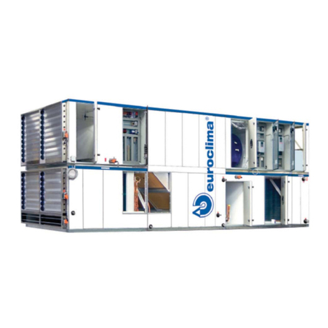
Euroclima ZHK NANO User manual

=+.1$12
,16758&7,210$18$/

instruction and operation manual ZHK NANO
V04-18 1 / 116
In addition to the instructions in this guide,
subject-specific standards, as well as local, national and
international regulations must be observed.
!
Please give this instruction manual after com-
pletion of the work to the operating staff of the
AHU. Please keep the complete instruction and
operating manual at your documents.
!
ĞƚƌŝĞďƐĂŶůĞŝƚƵŶŐ
/ŶƐƚƌƵĐƚŝŽŶŵĂŶƵĂů
DĂŶƵĂůĞĚŝƐƚƌƵnjŝŽŶĞ
ET 174-0

instruction and operation manual ZHK NANO
V04-18 61 / 116
User manual
NANO V0.03
April 2018
+RWOLQH

instruction and operation manual ZHK NANO
62 / 116 V04-18
12 Display
12.1 Push buttons, rotary button
Figure 95: Display
The operation takes place via the elements described below:
xInfo-button return to the main / start page or application info page
off AHU off
green AHU on
green flashing AHU is starting (preheating) or stopping
orange only one fan is running
xAlarm-button show alarms (see chapter 11)
off no alarm
red flashing not acknowledged alarm is active
red alarms are active
xESC-button return to the previous menu page
cancel a value change
push long display service page (contrast, color, backlight, brightness)
xOk-button multifunctional push and rotary button
rotate select a menu / line, select / change value
push ok, go to a submenu, confirm a changed value
push long go to the password page, log in / log out
possible at any time in any menu

instruction and operation manual ZHK NANO
V04-18 63 / 116
12.2 Display
The display is divided into several areas:
6WRS$ODUP
Ÿ $OOVHWWLQJV Ź
2SHUDWLQJPRGH 2II
2 WGRRUWHPS &
6 SSO\WHPS &
5HW UQWHPS &
6 SSO\IORZ PK
ź 5HW UQIORZ PK
Figure 96: Start page
xHeadline on the main / start page: date, time and AHU state
in a submenu: the current selected submenu
xFurther lines arrows indicate additional lines above/below
xCurrent line / total lines current selected line / total number of lines
xSubmenu submenu, press Ok to go into the submenu
xValues, states display the current values, states and the setpoints / settings
The language can be selected via All settings ĺ/DQJXDJH.
Depending on the configuration of the AHU, more or less lines are displayed.
12.3 Password
For every entry a password is needed (except language selection); the current access level is dis-
played in the left top corner:
xNo key level 253 no change of settings possible, only a few parts
of the menus are visible
(language selection is always possible)
x1 key level 6 user level, change of setpoints / settings
level 5 extra user level, special settings
Password for user level
1000
(for OHYHOWKHSDVVZRUGLV VHUSDVVZRUGĺ
After 10 minutes the display makes an automatic logout and returns to the main / start page.
12.4 Operation, value entry
For the operation of the display, the rotary button and the ESC-button are primarily used. The ro-
tary button is used to select the desired line. Depending on the type of line a value / state is dis-
played, a setpoint is entered, a setting is made or a submenu is selected.
Line
current / total
Submenu
Values, states
Headline
Further lines
Password level

instruction and operation manual ZHK NANO
64 / 116 V04-18
12.4.1 Line with submenu
An arrow right next to the line indicates a submenu; the line can be selected with the rotary button
and the submenu can be entered with Ok.
12.4.2 Value, setpoint
Select the line of the setpoint to be changed and confirm with Ok; a new page displays the setpoint
with the limits and the location of the setpoint within the limits with an arrow on the bar.
Keep turning the rotary button until the desired value is set to change a value; after prolonged turn-
ing the active position will automatically switch to the next higher (once 10 numbers have been run
through); if the rotary button is not turned for some seconds, the active position will switch back to
the next lower. For better orientation this is illustrated by an arrow above the number. Thus, large
numerical ranges are adjusted quickly.
ź
Ŋņņņŏņņņŏņņņŏņņņŏņņņŏņņņŏņņņŋ
PKPK
Ļ
PK
Figure 97: Set value, setpoint
12.4.3 Selection, setting, function
Select the line of the setting / selection / function to be changed with the rotary button and confirm
with Ok; A new page displays a list of possible settings with a ¥QH[WWRWKHF UUHQWVHWWLQJ6HOHFWD
new setting with the rotary button and confirm with Ok.
ϭϱ
¥5HW&DVF
6 SSO\
5HW UQ
5RRP&DVF
5RRP
Figure 98: Selection (e.g. supply air control)
12.4.4 ESC-button
The ESC-button has different functions:
xDuring the change of a setpoint or setting, this will be cancelled and the old value is
retained
xWithin a menu to return to the next higher menu
xBy pressing and holding the button, the system page of the display is called up; there the
color, contrast and brightness of the backlighting can be changed

instruction and operation manual ZHK NANO
V04-18 65 / 116
12.4.5 Adjustability
If a line is selected, the text appears on the left white on a black background. Is also the value
white on black background, then the value is adjustable, otherwise not. An adjustment is not possi-
ble without registration.
7HPSHUDW UHVHWSRLQWV
Ÿ 6 SSO\WHPSPLQ &
6 SSO\WHPSPD[ &
6DW UDWLRQWHPS &
6 PPHUFRPSHQVDWLRQ & Ź
+HDWVHW &
&RROVHW &
&RQWUROOHGWHPS &
Figure 99: Value adjustable
7HPSHUDW UHVHWSRLQWV
Ÿ 6 SSO\WHPSPLQ &
6 SSO\WHPSPD[ &
6DW UDWLRQWHPS &
6 PPHUFRPSHQVDWLRQ & Ź
+HDWVHW &
&RROVHW &
&RQWUROOHGWHPS &
Figure 100: Value not adjustable
13 Main / start page
The main / start page with the most important values and settings of the AHU is displayed after
powering on the controller:
6WRS$ODUP
Ÿ $OOVHWWLQJV Ź
2SHUDWLQJPRGH 2II
2 WGRRUWHPS &
6 SSO\WHPS &
5HW UQWHPS &
6 SSO\IORZ PK
ź 5HW UQIORZ PK
Figure 101: Main / start page
xDate, time and AHU state / operating mode source
xSubmenu for all settings
xOperating mode (switch on / off the AHU)
xTemperatures (outdoor, supply air, return air, ...)
xHumidity (supply air, return air)
xAir flow rate, duct pressure and fan speed

instruction and operation manual ZHK NANO
66 / 116 V04-18
xPower of the recovery
xValve positions and pumps for heating and cooling batteries
xHumidifier
The state display shows the current operating mode / operating mode source of the AHU:
x- no request
xStart start phase, initialization
xConfig configuration changed; AHU blocked
xStop / alarm AHU blocked (Alarm emergency stop)
xDisplay command from operating display
xBMS command from BMS
xRoom unit command from room unit
xScheduler command from scheduler
The different possibilities of the request (switching AHU on / off or operating mode) have different
priorities; so the AHU is switched off when the command from the display is Off, even if the sched-
OHURUWKH%06UHT HVWLVHFRQRP\RUFRPIRUW7KHSULRULW\FRUUHVSRQGVWRWKHDERYHOLVW³&RQILJ´
KDVWKHKLJKHVWDQG³6FKHG OHU´WKHORZHVWSULRULW\$SSHDUVLQWKHGLVSOD\-, then there is no re-
quest active (display, BMS and room unit have the state Auto, the scheduler is not active).
13.1 All settings
By the line All settings, the submenu All settings can be entered; by several submenus the display
pages for setpoints, operation mode, alarm state, password handling and language setting can be
entered.
$OOVHWWLQJV
6HWSRLQWVVHWWLQJV Ź
2SHUDWLRQPRGHVFKHG OHU Ź
$ODUPVWDWH Ź
3DVVZRUGKDQGOLQJ Ź
/DQJ DJH (QJOLVK
Figure 102: All settings
xSetpoints / settings VHWSRLQWVIRUWHPSHUDW UHK PLGLW\DLUT DOLW\«
xOperation mode / scheduler operation mode, scheduler, date / time setting
xAlarm states alarm states
xPassword handling enter passwords, change passwords
xLanguage language selection (English, Italian, German)
14 Setpoints / settings
The setting of the setpoints is performed separately for the airflow rate, temperature, humidity, air
quality and night setback.

instruction and operation manual ZHK NANO
V04-18 67 / 116
6HWSRLQWVVHWWLQJV
)ORZUDWH Ź
7HPSHUDW UH Ź
+ PLGLW\ Ź
$LUT DOLW\ Ź
1LJKWVHWEDFN
Figure 103: Setpoints/settings
14.1 Fan setpoints
The air flow rate, duct pressure, fan stage or fan speed is set via this page of the display; depend-
ing on the operating mode, more or less or no settings can be changed.
14.1.1 Operating mode of the fan control
The fan control has 3 possible operating modes; the operating mode is set during the commission-
ing and cannot be changed.
Airflow rate control
)DQVHWSRLQWV
6 SSO\(FR PK
6 SSO\&RPIRUW PK
5HW UQ(FR PK
5HW UQ&RPIRUW PK
1LJKWVHWEDFN Ź
6 SSO\VHW PK
Figure 104: Airflow rate control
At the airflow rate control, one setpoint for economy, comfort mode and night setback will be set
separately for supply and return air. Thus, it can be adjusted as desired overpressure (supply air-
flow > return airflow) or a negative pressure (supply airflow < return airflow). The setting is made in
m³ / h. The last 2 lines show the current setpoints for the fan control.
If an air quality control by means of the airflow rate is active, the maximum airflow rate for poor air
quality can also be set. The resulting airflow rate is then the maximum of the setpoint for economy /
comfort mode and air quality control. Thus, the selected airflow rate is always adhered and in-
creases due to poor air quality. The setting is made in the menu Air quality, which can be entered
directly.
If the dehumidification by means of the airflow rate is active, the maximum airflow rate for high hu-
midity can also be set. The resulting airflow rate is then the maximum of the setpoint for economy /
comfort mode and the dehumidification control. Thus, the selected flow rate is always adhered and
increases due to high room humidity. The setting is made in the menu Humidity, which can be en-
tered directly.

instruction and operation manual ZHK NANO
68 / 116 V04-18
In the night setback mode, the rooms can be cooled with the cool outdoor air outside normal work-
ing hours; all heating batteries, cooling batteries, recovery systems, humidity and air quality control
are disabled. The setting is made in the menu Night setback, which can be entered directly.
If a room unit or remote switch is connected, the airflow can be changed via this with a correspond-
ing configuration (offset).
6HWSRLQW
'HVFULSWLRQ
'HIDXOW
6 SSO\(FR
6 SSO\DLUIORZUDWHIRUHFRQRP\PRGH
+DOIQRPLQDODLUIORZ
UDWH
6 SSO\&RPIRUW
6 SSO\DLUIORZUDWHIRUFRPIRUWPRGH
1RPLQDODLUIORZUDWH
5HW UQ(FR
5HW UQDLUIORZUDWHIRUHFRQRP\PRGH
+DOIQRPLQDODLUIORZ
UDWH
5HW UQ&RPIRUW
5HW UQDLUIORZUDWHIRUFRPIRUWPRGH
1RPLQDODLUIORZUDWH
6 SSO\VHW
& UUHQWV SSO\DLUIORZUDWHVHWSRLQW
«PñK
5HW UQVHW
& UUHQWUHW UQDLUIORZUDWHVHWSRLQW
«PñK
Table 8: Airflow rate setpoints
The setpoints for night setback, air quality and humidity control can be found in the chapters night
setback (14.5 Night setback), air quality control (14.4.1.3 Fan speed) and humidity control
(14.4.1.1 CO2 sensor).
Pressure control
When the fans are controlled by the duct pressure, the required pressure setpoint is set at commis-
sioning separately for supply and return air and is equal for economy and comfort mode. This is
visible, but can be changed only by service personnel. The current air flow rate is always visible on
the main page.
An air quality control or dehumidification is not possible, because the amount of air cannot be
changed and depends only on the external duct pressure.
If air quality control is provided by means of duct pressure, the maximum duct pressure can also
be set at poor air quality. The resulting duct pressure is then the maximum of the setpoint for econ-
omy / comfort mode and air quality control. Thus, the selected duct pressure is always maintained
and increased due to poor air quality. The setting is made in the menu "air quality", which can be
entered directly.
If the dehumidification is activated by means of duct pressure, the maximum duct pressure can
also be set at high humidity. The resulting duct pressure is then the maximum of the setpoint for
economy / comfort mode and dehumidification control. Thus, the selected duct pressure is always
maintained and increased due to high room humidity. The setting is made in the menu "humidity",
which can be entered directly.
6HWSRLQW
'HVFULSWLRQ
'HIDXOW
6 SSO\G FWSUHVV
6 SSO\DLUG FWSUHVV UHVHWSRLQW
6HHGDWDVKHHW
5HW UQG FWSUHVV
5HW UQDLUG FWSUHVV UHVHWSRLQW
6HHGDWDVKHHW
Table 9: Duct pressure setpoints

instruction and operation manual ZHK NANO
V04-18 69 / 116
Speed control
Similar to the airflow rate control the speed for economy, comfort and night setback mode can be
set. The fans are operated at the set speed, regardless of airflow rate or duct pressure.
In addition, the speed is increased by air quality control or dehumidification when the air quality is
poor or the humidity is high. Also, an adjustment of the speed for poor air quality and high humidity
is possible. The setting of the speed for night setback, air quality and dehumidification occurs in
separate menus, which can be entered directly.
6HWSRLQW
'HVFULSWLRQ
'HIDXOW
6 SSO\(FR
6 SSO\IDQVSHHGIRUHFRQRP\PRGH
6 SSO\&RPIRUW
6 SSO\IDQVSHHGIRUFRPIRUWPRGH
5HW UQ(FR
5HW UQIDQVSHHGIRUHFRQRP\PRGH
5HW UQ&RPIRUW
5HW UQIDQVSHHGIRUFRPIRUWPRGH
6 SSO\VHW
& UUHQWV SSO\IDQVSHHGVHWSRLQW
5HW UQVHW
& UUHQWUHW UQIDQVSHHGVHWSRLQW
Table 10: Speed settings
The setpoints for night setback, air quality and humidity control can be found in the chapters night
setback (14.5 Night setback), air quality control (14.4.1.3 Fan speed) and humidity control
(14.4.1.1 CO2 sensor).
14.2 Temperature setpoints
The control mode for the temperature control and the corresponding setpoints are set via the tem-
perature setpoints. Depending on the execution of the AHU, additional calculated setpoints for the
saturation temperature are displayed over which the dehumidification is controlled.
7HPSHUDW UHVHWSRLQWV
&RQWUROPRGH 5HW&DVF
$FW DOPRGH$ WR :LQWHU
+HDW(FR &
+HDW&RPIRUW &
&RRO(FR &
&RRO&RPIRUW &
ź 5RRP &
Figure 105: Temperature setpoints
14.2.1 Operating mode of the temperature control
There are up to 5 operating modes for the temperature control, which can be set by the user. If no
room unit is present, then only 3 operating modes can be selected. If the AHU is a pure supply air
unit, then the return air control cannot be set. In order to make the right setting is the understand-
ing of the individual operating modes very important. Service engineers or planners can give you
more informatio

instruction and operation manual ZHK NANO
70 / 116 V04-18
Return air cascade (RetCasc)
The return air temperature is used as a control variable. The supply air setpoints for the heating
batteries and cooling batteries are calculated by the deviation between the current return air tem-
perature and the setpoints. The activation of the valves and the recovery is performed based on
the deviation between the current supply air temperature and the calculated supply air setpoints.
The calculated supply air setpoints cannot exceed the minimum / maximum supply air limit.
A dead zone can be defined between the setpoints for heating and cooling, by which a deactivation
of the heating batteries and cooling batteries can be achieved (energy saving). They are deac-
tivated as long as the return air temperature is in the dead zone. The adjustment of setpoints is
performed separately for economy and comfort mode.
This control strategy combines the return air temperature control with a supply air temperature con-
trol. It is used when the return air temperature should be kept constant and can be used for infi-
nitely variable heating / cooling batteries (water batteries).
6HWSRLQW
'HVFULSWLRQ
'HIDXOW
+HDW(FR
+HDWLQJVHWSRLQWIRUHFRQRP\PRGH
&
+HDW&RPIRUW
+HDWLQJVHWSRLQWIRUFRPIRUWPRGH
&
&RRO(FR
&RROLQJVHWSRLQWIRUHFRQRP\PRGH
&
&RRO&RPIRUW
&RROLQJVHWSRLQWIRUFRPIRUWPRGH
&
Table 11: Setpoints for cascade temperature control
Supply air
The supply air temperature is used as control variable. The recovery, heating and cooling batteries
are activated depending on the deviation between the current supply air temperature and the set-
points.
A dead zone can be defined between the setpoints for heating and cooling, by which a deactivation
of the heating batteries and cooling batteries can be achieved (energy saving). They are deac-
tivated as long as the supply air temperature is in the dead zone. The adjustment of setpoints is
performed separately for economy and comfort mode.
This control strategy is mainly used in downstream heating or cooling units, which are not con-
trolled by the AHU.
6HWSRLQW
'HVFULSWLRQ
'HIDXOW
+HDW(FR
+HDWLQJVHWSRLQWIRUHFRQRP\PRGH
&
+HDW&RPIRUW
+HDWLQJVHWSRLQWIRUFRPIRUWPRGH
&
&RRO(FR
&RROLQJVHWSRLQWIRUHFRQRP\PRGH
&
&RRO&RPIRUW
&RROLQJVHWSRLQWIRUFRPIRUWPRGH
&
Table 12: Setpoints for supply air temperature control
Return air
The return air temperature is used as control variable. The recovery, heating and cooling batteries
are activated depending on the deviation between the current return air temperature and the set-
points. This control is directly performed causing the supply air temperature is subjected to greater

instruction and operation manual ZHK NANO
V04-18 71 / 116
fluctuations. The limiting function of the supply air tries to limit the battery power to comply with the
specified minimum and maximum values.
A dead zone can be defined between the setpoints for heating and cooling, by which a deactivation
of the heating batteries and cooling batteries can be achieved (energy saving). They are deac-
tivated as long as the return air temperature is in the dead zone. The adjustment of setpoints is
performed separately for economy and comfort mode.
This control strategy is mainly used for stage controlled cooling / heating, e.g. in a cooling by
means of a direct evaporator (compressor) and is better suited than the cascade or supply air tem-
perature control, because the air temperature is subjected to greater fluctuations by the compres-
sor and no constant supply air temperature is possible.
6HWSRLQW
'HVFULSWLRQ
'HIDXOW
+HDW(FR
+HDWLQJVHWSRLQWIRUHFRQRP\PRGH
&
+HDW&RPIRUW
+HDWLQJVHWSRLQWIRUFRPIRUWPRGH
&
&RRO(FR
&RROLQJVHWSRLQWIRUHFRQRP\PRGH
&
&RRO&RPIRUW
&RROLQJVHWSRLQWIRUFRPIRUWPRGH
&
Table 13: Setpoints for return air temperature control
Room cascade (RoomCasc)
This control strategy works the same as the return air cascade, only that the room temperature of a
room unit or room sensor is used as control variable. The adjustable offset at the room unit affects
the heating / cooling setpoints.
This control strategy is only available if a room unit or a room sensor is present and is used when
the return air temperature is heavily distorted and is an inappropriate control variable or the room
temperature should be used directly. The setpoint settings match the settings of the return air cas-
cade (14.2.1.1).
If a room unit and a room sensor are installed, then the room sensor is used and the sensor of the
room unit has no function.
Room
This control strategy works the same as the return air control, only that the room temperature of a
room unit or room sensor is used as control variable. The adjustable offset at the room unit affects
the heating / cooling setpoints.
This control strategy is only available if a room unit is present and is used when the return air tem-
perature is heavily distorted and is an inappropriate control variable or the room temperature
should be used directly. The setpoint settings match the settings of the return air (14.2.1.3).
If a room unit and a room sensor are installed, then the room sensor is used and the sensor of the
room unit has no function.

instruction and operation manual ZHK NANO
72 / 116 V04-18
14.2.2 AHU with 3 batteries (saturation temperature)
If the device has a preheating battery, a cooling battery and a postheating battery, then a satura-
tion temperature sensor can be mounted after the cooling battery. By this sensor, the first two bat-
teries can be controlled, whereby the setpoint for this measurement point is lowered at a dehumidi-
fication requirement. The lowest setpoint can be set in the access level 5. This function is only pos-
sible when:
x2 heating batteries and 1 cooling battery are present
xa saturation temperature sensor is present
xreturn air cascade, supply air or room cascade is set as control strategy
6HWSRLQW
'HVFULSWLRQ
'HIDXOW
6DW UDWLRQWHPS
0LQLP PVDW UDWLRQWHPSHUDW UH
&
Table 14: Saturation temperature setpoint
14.2.3 Supply air limitation
The supply air temperature is always limited:
xthe supply air setpoint cannot exceed the limits, if the cascade control is active
xno setpoint is allowed to exceed the limits, if the supply air control is active
xthe supply air temperature is limited by separately adjustable controller, if the return air
control and room control are active
6HWSRLQW
'HVFULSWLRQ
'HIDXOW
0LQV SSO\DLUWHPS
0LQLP POLPLWIRUWKHV SSO\DLUVHWSRLQW
&
0D[V SSO\DLUWHPS
0D[LP POLPLWIRUWKHV SSO\DLUVHWSRLQW
&
Table 15: Supply air temperature limits
14.2.4 Summer / winter compensation
Via the summer compensation, cooling setpoints can be raised at high outside temperatures to
keep the difference between outdoor and indoor temperature low or to save cooling energy; heat-
ing setpoints are not affected.
Via the winter compensation, heating setpoints can be raised or lowered at low outdoor tempera-
tures; cooling setpoints are not affected.
6 PPHUFRPSHQVDWLRQ
6WDUW &
(QG &
'HOWD &
&DOF ODWHG &
Figure 106: Summer compensation

instruction and operation manual ZHK NANO
V04-18 73 / 116
6HWSRLQW
'HVFULSWLRQ
'HIDXOW
6 PPHUFRPSHQVDWLRQ
6WDUW
2 WGRRUWHPSHUDW UHVWDUWSRLQWIRUVKLIW
&
(QG
2 WGRRUWHPSHUDW UHHQGSRLQWIRUVKLIW
&
'HOWD
6KLIWYDO HRIWKHFRROLQJVHWSRLQWVDWWKHHQGSRLQW
&
&DOF ODWHG
6KLIWG HWRWKHF UUHQWR WGRRUWHPSHUDW UH
«&
:LQWHUFRPSHQVDWLRQ
6WDUW
2 WGRRUWHPSHUDW UHVWDUWSRLQWIRUVKLIW
&
(QG
2 WGRRUWHPSHUDW UHHQGSRLQWIRUVKLIW
&
'HOWD
6KLIWYDO HRIWKHFRROLQJVHWSRLQWVDWWKHHQGSRLQW
&
&DOF ODWHG
6KLIWG HWRWKHF UUHQWR WGRRUWHPSHUDW UH
«&
Table 16: Summer / winter compensation settings
14.2.5 Setpoint and control variable
At the end of the page, the currently used setpoints and the current control variable are displayed,
which vary depending on the control strategy.
7HPSHUDW UHVHWSRLQWV
6 SSO\WHPSPLQ &
6 SSO\WHPSPD[ &
6 PPHUFRPSHQVDWLRQ & Ź
&RQWUROOHGWHPS &
+HDWVHW &
&RROVHW &
Figure 107: Current setpoints
6HWSRLQW
'HVFULSWLRQ
'HIDXOW
&RQWUROOHGWHPS
& UUHQWFRQWUROYDULDEOHUHW UQDLUV SSO\DLU
RUURRPWHPS
«&
+HDWVHW
& UUHQWVHWSRLQWIRUUHFRYHU\KHDWLQJ
EDWWHULHV
«&
&RROVHW
& UUHQWVHWSRLQWIRUFRROLQJEDWWHULHV
«&
Table 17: Heat / cool setpoint and controlled temperature
14.2.6 Recirculation damper
The recirculation damper is not modulating, but is opened or closed depending on the heating re-
quirement and the set base time (60min). The recirculation damper operates as the last heating
sequence for temperature regulation (unless dehumidification by means of recirculation damper
has been configured). For example: recirculation damper requirement = 50%, i.e. with a base time

instruction and operation manual ZHK NANO
74 / 116 V04-18
of 60 minutes, the ventilator operates 30 minutes in fresh air mode and 30 minutes in recirculated
air mode (in this mode, the return fan is at a standstill). In case of an additional air quality control
by the recirculation damper, the air quality has a higher priority.
14.3 Humidity setpoints
Depending on the execution of the AHU can be dehumidified, humidified or dehumidified and hu-
midified; the display differs depending on the execution.
+ PLGLW\VHWSRLQWV
&RQWUROPRGH 5HW UQ
+ PLGLILFDWLRQ(FR
+ PLGLILFDWLRQ&RP«
'HK PLGLILFDW(FR
'HK PLGLILFDW&RPI«
0D[V SSO\
+ PLGLILHU
Figure 108: Humidification / dehumidification set-
points
14.3.1 Control mode for humidification and dehumidification
Depending on the execution of the AHU, the operating mode of the control can be chosen between
return air, supply air and room.
14.3.2 Return air control
Normally, the humidification and dehumidification is controlled via the return air humidity. Thus, the
desired room humidity is kept within specified limits; the room humidity should be between 40%
and 60%.
14.3.3 Supply air control
In pure supply air devices and if no return air sensor or room humidity sensor is present, then it is
controlled via the supply air humidity; this is then kept within specified limits. Since not the room
humidity is measured, the response of the room must be considered when entering the setpoints.
Depending on the application, higher humidification setpoints in winter and lower dehumidification
setpoints in summer may be necessary.
14.3.4 Dehumidification with cooling battery
For dehumidification, the supply air is cooled and again heated up by the heating battery, thus re-
sulting in a dry supply air. In the best case the AHU is equipped with 3 batteries (see also chapter
14.2.2 saturation temperature), whereby the dehumidification lowers the saturation temperature,
which is an independent control circuit for temperature control and the postheating battery again
raises the supply air temperature.
The water cooling battery, compressor cooling battery or both are used.

instruction and operation manual ZHK NANO
V04-18 75 / 116
14.3.5 Dehumidification with recirculation damper
For the dehumidification by means of the recirculation damper, the absolute humidity of the supply
air and of the exhaust air is compared. In case of a higher supply air humidity (corresponds to the
fresh air humidity in the fresh air mode), it is switched to recirculated mode as a function of the de-
humidification requirement (see chapter 14.2.6 for more information), in order to not increase the
absolute humidity content. In case of an additional air quality control by the recirculation damper,
the air quality has a higher priority.
6HWSRLQW
'HVFULSWLRQ
'HIDXOW
0LQIUHVKDLU
0LQLP PRSHQLQJSRVLWRQIRUWKHIUHVKDLUGDPSHU
0D[IUHVKDLU
0D[LP PRSHQLQJSRVLWLRQIRUWKHIUHVKDLUGDPSHU
Table 18: Fresh air dehumidification with recirculation damper
14.3.6 Dehumidification with damper / cooling, cooling / damper
In this case the dehumidification is done by increasing the amount of recirculation air and then acti-
vating the cooling battery or exactly the opposite.
14.3.7 Setpoints
The setpoints for humidification and dehumidification are entered separately for economy and com-
fort mode. If no humidifier is selected, then no humidification setpoints can be entered. If dehumidi-
fication is not possible, then no dehumidification setpoints can be entered. At the same time, a
maximum supply air limit for the return air humidity control can be configured. The current humidifi-
cation and dehumidification request is displayed.
6HWSRLQW
'HVFULSWLRQ
'HIDXOW
+ PLGLILFDWLRQ(FR
+ PLGLILFDWLRQVHWSRLQWIRUHFRQRP\PRGH
+ PLGLILFDWLRQ&RPIRUW
+ PLGLILFDWLRQVHWSRLQWIRUFRPIRUWPRGH
'HK PLGLILFDWLRQ&RPIRUW
'HK PLGLILFDWLRQVHWSRLQWIRUFRPIRUWPRGH
'HK PLGLILFDWLRQ(FR
'HK PLGLILFDWLRQVHWSRLQWIRUHFRQRP\PRGH
0D[V SSO\
0D[LP PV SSO\DLUK PLGLW\OLPLW
+ PLGLILHU
& UUHQWSRZHUUHT HVWIRUK PLGLILHU
'HK PLGLILFDWLRQ
& UUHQWGHK PLGLILFDWLRQUHT HVW
Table 19: Humidification / dehumidification setpoints
14.4 Air quality setpoints
The air quality is measured by an air quality sensor in the return air and is controlled by the amount
of air or the recirculation damper. Sensor type and control mode are configured at commissioning
and cannot be changed.

instruction and operation manual ZHK NANO
76 / 116 V04-18
$LUT DOLW\VHWSRLQWV
&2(FR SSP
&2&RPIRUW SSP
&RQWUROVLJQDO
6 SSO\PD[ PK
5HW UQPD[ PK
Figure 109: Air quality
14.4.1 Sensor type, control procedures
One type of sensor and one control procedure come into use, depending on the execution of the
AHU.
CO2 sensor
This sensor measures the CO2concentration [ppm] in the return air; the higher the concentration,
the worse the air quality. As a guide for the setting of the CO2concentration, the following table
can be used.
$LUTXDOLW\
&2FRQFHQWUDWLRQ
2 WGRRUDLUJRRGT DOLW\
aSSP
5RRPZLWKJRRGDLUT DOLW\
SSP
5RRPZLWKPHGL PDLUT DOLW\
«SSP
5RRPZLWKPRGHUDWHDLUT DOLW\
«SSP
5RRPZLWKORZDLUT DOLW\
!SSP
Table 20: Room air quality
Recirculation damper
For the control of the air quality by means of a recirculation damper, it is possible to determine
whether the air quality has priority (default setting: Yes). Depending on the requirements, the fresh
air mode is active for a prolonged period (see chapter 14.2.6 for the method of operation).
6HWSRLQW
'HVFULSWLRQ
'HIDXOW
0LQIUHVKDLU
0LQLP PRSHQLQJSRVLWLRQIRUWKHIUHVKDLU
GDPSHU
0D[IUHVKDLU
0D[LP PRSHQLQJSRVLWLRQIRUWKHIUHVKDLU
GDPSHU
Table 21: Fresh air for air quality control
Fan speed
In case of good air quality, the AHU is operated with the airflow rate, speed or duct pressure speci-
fied by the operating modes economy and comfort; this setting should be as low as possible. If the

instruction and operation manual ZHK NANO
V04-18 77 / 116
air quality decreases, then the airflow rate, speed or duct pressure increases to an adjustable max-
imum value. This operating mode can only be used for airflow rate, speed or duct pressure control.
The air flow rate, speed or operating stage specified by the economy or comfort mode is always
kept and is increased by the air quality control.
6HWSRLQW
'HVFULSWLRQ
'HIDXOW
&2(FR
&2VHWSRLQWIRUHFRQRP\PRGH
SSP
&2&RPIRUW
&2VHWSRLQWIRUFRPIRUWPRGH
SSP
&RQWUROVLJQDO
5HT HVWHGIUHVKDLUDPR QWRUDLUIORZUDWH
6 SSO\PD[
0D[LP PV SSO\DLUIORZUDWHIRUSRRUDLU
T DOLW\
0D[LP PV SSO\IDQVSHHGIRUSRRUDLU
T DOLW\
1RPLQDOYDO H
5HW UQPD[
0D[LP PUHW UQDLUIORZUDWHIRUSRRUDLU
T DOLW\
0D[LP PUHW UQIDQVSHHGIRUSRRUDLU
T DOLW\
1RPLQDOYDO H
6 SSO\VHW
& UUHQWV SSO\DLUIORZUDWHIDQVSHHG
UHT HVW
«PñK«
5HW UQVHW
& UUHQWUHW UQDLUIORZUDWHIDQVSHHG
UHT HVW
«PñK«
Table 22: Air quality setpoints
14.5 Night setback
The operating mode Night setback is a special operating mode, which can be selected via the
scheduler, the display or the BMS.
In the night setback mode, the rooms shall be cooled with cool outdoor air to save cooling energy
the next day. The AHU is operated with the separately adjusted airflow rate, speed or duct pres-
sure. The recovery system, all heating and cooling batteries, humidification and dehumidification
are inactive.
Night setback starts according to the operating mode switch (e.g. scheduler at 0:00) when the out-
door temperature is above 12 °C, the room temperature is 3 °C above the setpoint (22 °C) and the
outdoor temperature is at least 5 °C below the room temperature. Night setback will run as long as
the outdoor temperature is above 12 °C, the room temperature is at least 1 °C above the setpoint
(22 °C) and the outdoor temperature is at least 1 °C below room temperature. A minimum operat-
ing period of 30 min guarantees, that it will not immediately be switched off after starting.
Several settings are set during commissioning. The room temperature setpoint and the minimum
operating period, air flow rate, speed or operation stage can be set in the Night setback menu.
If no room sensor and outdoor temperature sensor are present, then the return air temperature and
fresh air temperature are used. For this purpose, these are cyclically tested for 5 min every hour; if
the conditions are met, then the night setback mode continues operating.

instruction and operation manual ZHK NANO
78 / 116 V04-18
1LJKWVHWEDFN
5RRPVHWSRLQW &
0LQU QWLPH PLQ
6 SSO\ PK
5W UQ PK
Figure 110: Night setback
6HWSRLQW
'HVFULSWLRQ
'HIDXOW
5RRPVHWSRLQW
5RRPWHPSHUDW UHVHWSRLQWIRUQLJKWVHWEDFN
&
0LQU QWLPH
0LQLP PRSHUDWLQJWLPHHYHQLIWKH
FRQGLWLRQVDUHQRORQJHUPHW
PLQ WHV
6 SSO\
6 SSO\DLUIORZUDWHV SSO\IDQVSHHG
1RPLQDOYDO H
5HW UQ
5HW UQDLUIORZUDWHUHW UQIDQVSHHG
1RPLQDOYDO H
Table 23: Night setback setpoints
15 Operating mode / scheduler
The on / off switching and the operating mode economy or comfort are determined by a variety of
sources, which have different priorities. A source with a higher priority overrides all lower prioritized
sources.
xHMI Request from HMI (Off, NightStb, Eco, Comfort, Auto)
with Auto the operating mode is determined by the BMS
xBMS Request from BMS (Off, NightStb, Eco, Comfort, Auto)
with Auto the operating mode is determined by the room unit
xRoom unit Request from room unit (Off, Eco, Comfort, Auto)
with Auto the operating mode is determined by the scheduler
xScheduler Request from scheduler (Off, NightStb, Eco, Comfort)
with no entry (display -) the AHU is off
Note: the AHU can be started and stopped at the electric cabinet (operating display
mounted on the electric cabinet) by setting the operating mode of the HMI.
Depending on the execution of the AHU, individual control devices / lines are not displayed; room
unit and building management system are optional. Only the operating mode of the HMI and, with
the expanded customer password, the building management system setting is adjustable (for test
purposes and in case of failure).
The current mode is displayed next to each control device. The Operating mode line shows the re-
sulting operating mode, which results from the various control devices and the scheduler. The
Scheduler line shows the resulting operating mode switch of the scheduler, which results from the
scheduler setting.
Other manuals for ZHK NANO
3
Table of contents
Other Euroclima Fan manuals
Popular Fan manuals by other brands

Concept2
Concept2 VS5013 manual

Delta
Delta breez REC80LED Installation and operating instructions

Gulf Coast Fans
Gulf Coast Fans 4YU26 owner's manual

VES
VES AX315/4-1 Installation, operation & maintenance manual

Three Sixty
Three Sixty Arumi AC Series Owner's and installer's manual

Flex-a-Lite
Flex-a-Lite 30 quick start guide