EuroFans MONTANA Setup guide

OWNERS INSTRUCTION
MANUAL
INSTALLATION
OPERATION
MAINTENANCE
1
CAUTION
READ INSTRUCTIONS CAREFULLY FOR SAFE INSTALLATION AND
FAN OPERATION. IF UNSURE CONSULT
A QUALIFIED ELECTRICIAN
SUITABLE FOR 230V/50 CYCLE ELECTRICAL SUPPLY
Enquiries on installing your fan please call our help line on
01959-564440
technical@fantasiaceilingfans.com
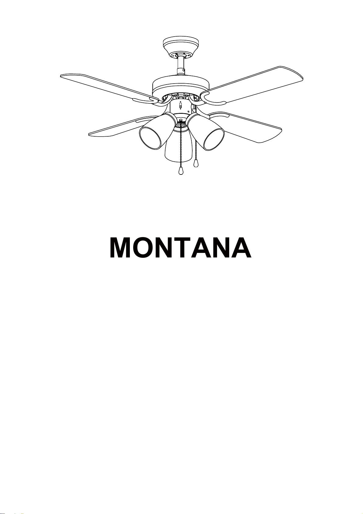
MONTANA
106CM/42” or 91CM/36”

3
Safety Precautions
1.
To
ensure
the
success
of
the
installation
be
sure
to
read
the
instructions
and
study
the
diagrams
thoroughly
before
commencing.
2.
All
electrical
work
should
only
be
undertaken
after
disconnection
of
the
power
by
removing
fuses
or
turning
off
the
circuit
breaker
to
ensure
all
pole
isolation
of
the
electrical
supply.
If
you
are
in
any
doubt
the
services
of
a
qualified
electrician
should
be
sought
to
ensure
that
all
work
is
carried
out
in
accordance
with
the
I.E.E.
Regulations,
current
good
practice
and
other
national
and
local
electrical
codes.
3.
Make
sure
that
your
installation
situ
will
not
allow
the
rotating
fan
blades
to
come
into
blade tip to the wall or ceiling. Please note that the bigger this clearance is the better
the airflow from your fan will be. Ensure the blades are mounted at a minimum height
4. The fixing point for the fan must be able to support a weight of ten times that of the net
wei
support the moving weight of the fan and must not twist or work loose.
5. The fan must be earthed.
6. Do not connect the fan motor to a dimmer switch. This may give an unsatisfactory
performance (motor hum) and cause damage to the motor.
7. It is not recommended that ceiling fans and gas appliances are operated in the same
room at the same time.
8. The fan must be turned off and stopped completely before reversing the fan direction.
This will prevent any damage to the motor of the unit or controller (if installed).
9. Do not insert anything into the fan blades while the fan is operating. This will damage
the blades and upset the balance of the unit causing the unit to wobble.
10. After the fan is completely installed make sure that all connections are secure
andtight to prevent any problems.
11. osen. Check the
support connections, brackets and blade attachments twice a year to make sure they
are all secure. If they are loose tighten with a screwdriver.
Note: The important safeguards and instructions given in this manual are not meant to
cover all possible conditions and situations that may occur. It must be understood that
common sense, caution and care are factors, which cannot be built into any product.
These factors must be supplied by the persons caring for and using the unit.
For installation advice, or in the unlikely event of damaged or missing parts please ring:
HELPLINE: (01959) 564 440
1
Supplied Parts
One fan AC motor assembly
One hanger bracket fitted with terminal block and top rubber washers.
One set of blades
One set of blade carriers
One 3 llght llght kit
One screw-pack with balancing kit
One installation booklet.
Tools and Materials Required
Philips screwdriver
Blade screwdriver
Small electrical screwdriver
Electrical pliers
Step ladder
Wiring supplies as required by current electrical practice
Bulbs if a light fitting is fitted / to be fitted
In-line crimps or other suitable connectors if an extension rod in excess
of 760mm (30 inch) is to be fitted.
Before starting the assembly and installation of your fan please ensure the safety
precautions have been read and understood.
Installation Difficulties, Missing or Damaged Parts
If you have any difficulty in installing your fan/light or if you are unfortunate enough to
find that your fan have been dispatched with parts missing or damaged please contact
our help-line on 01959 564 440. We will be very pleased to provide help or forward
replacements parts to your immediately.
In any communication with us please quote model reference, colour of the unit and the
part missing /damaged.
HELPLINE
01959 564440
technical@fantasiaceilingfans.com
2

ASSEMBLING AND HANGING YOUR CEILING FAN
NOTE:
Before installing ensure that you have all poles disconnection of the electricity supply and that
you refer to qualified electrician to ensure that all wiring is carried out in accordance with
I.E.E. Regulations, current good practice, national and local electrical codes.
A. CLOSE TO CEILING MOUNTING
STEP 1: HANGER BARCKET AND CANOPY INSTALLATION
Secure the hanger bracket to joist with wood screws, rubber and steel washers.
Please make sure it is secured firmly. (See Fig. 1)/page 4.
Release 3 screws from upper housing
Put the canopy pass the electrical supply leads and align the screws holes on the
boss which is on the top of housing. Use the three flush mount set screws
to screw the canopy onto the fan, please make sure it is screwed firmly.
It will cause wobble or risk the fan falling down if the canopy isn't screwed or
tightened correctly. (See Fig 2)/page 4
CAUTION: Be sure that the hanging location can support load of at 70 kilos.
(see Safety Precautions)
3
STEP 2 : BLADE ASSEMBLY
led on to theThe blades now need to be assemb
blade carriers. Note that blades can be
installed with either surface facing down.
Carefully unwrap the blades and carriers. Align
the bracket with the holes in the blades and use
the screws and fibre washers provided to connect
them.
The fibre washer should go on top the blade
between the head of the screw and the surface
of the blade. Ensure the screws are tightened
firmly. Repeat this process for all blades.
Install the blade carrier with blade on to the
motor, using the motor screws to secure it
(provided in screw pack). Please make sure it
is tightened fully. Be careful not to bend the
blades or the carrier brackets during
installation as this may result in an imbalance
and induce wobble.
If installing more than one fan be careful not to
mix the blade sets. Each set is carefully
manufactured to be evenly balanced, mixing
would break up a balanced set and again this
could induce wobble.

STEP 3 : LIGHT KIT INSTALLING
Unscrew three screws from switch cover of light kit
Connect the push plug for light kit of ceiling fan to push plug of light kit.
Blue to Blue wire
Orange to Orange
Carefully collect all wires into switch housing of ceiling fan, then install the light
kit to switch housing using the 3 screws. Ensure the light kit is secured
firmly. Please see drawing details on page 10 Assembly light kit.
STEP 4: HANGING
Hang the motor on mounting plate with temporary support (a hook)
(See Fig. 3)/page 4.
This is an aid while making the electrical connection.
STEP 5 : WIRING (See Page 9 )
CAUTION: Carefully read the WIRING INSTRUCTIONS and DIAGRAMS
Since improper installation may result in an electric short and
void the warranty
STEP 6 : FAN HANGING
Carefully push all wiring into canopy. Remove from hanging
hook and position fan motor on hanger bracket such that attachment screws align
with keyed slots on upper side of motor housing. Secure fan to hanger bracket
with serrated washers and screws provided (See Fig. 4). Ensure a good electrical
connection by breaking lacquer finish as this forms the earth.
STEP 7 : FAN CHECKING
Turn on the electricity. Check to see that the fans forward and
reverse speeds work properly see operating instructions.
4

FLUSH MOUNT STYLE ASSEMBLY DIAGRAMS
Fig.1
Fig.2
Fig.3 Fig.4
5
JOIST OR
BEAM
CEILING
WOOD SCREWS
MOUNTING
PLATE
ROUND
STEEL
(MAYBE ATTACHED
ON THE PLATE)

B. DROP ROD STYLE INSTALLATION
STEP 1 : HANGER BRACKET INSTALLATION
Secure the hanger bracket to joist with wood screws, rubber and steel washers.
Please
make sure it is secured firmly.
(See Fig. 6)/page 7.
CAUTION : Be sure that the mounting location can support load of
at 70 kilos. (see Safety Precautions )
STEP 2 : DROP ROD ASSEMBLY
Remove the cotter pin and split pin from the bottom of the drop rod. If a longer
drop rod is going to be used, transfer the ball joint and the earth wire to the
longer rod.
Put the drop rod through the flared end of the canopy and pass the electrical
supply leads from the top of the motor through the drop rod until they exit at the
top of the ball joint. Always ensure the rod passes through the canopy before
the rod is connected to the fan. If an extension rod longer than 30 inches is to be
used, the cables will need to be extended in an appropriate way. (SEE FIG. 7)
Loosen the drop rod set screws on the boss, which is on top of the motor and
insert the drop rod into the drop rod boss on top of the motor casing. Turn gently
to align the holes in the boss with those in the rod. Ease the cotter pin through
the boss and the rod taking care not to pinch or damage any cables. Fix in place
by replacing the split pin.
6
STEP 3 : BLADE ASSEMBLY
led on to the
The blades now need to be assemb
blade carriers. Note that blades can be
installed with either surface facing down.
Carefully unwrap the blades and blade carriers.
Align the bracket with the holes in the blades and
use the screws and fibre washers provided to
connect them.
The fibre washer should go on top the blade
between the head of the screw and the surface
of the blade. Ensure the screws are tightened up
firmly. Repeat this process for all blades.
Put blade carrier with blade on the motor. Using
motor screws to screw it (provided in screws
pack). Please make sure it is tight enough. Be
careful not to bend the blades or the carrier
brackets during installation as this may result in
an imbalance and induce wobble.
If installing more than one fan be careful not to
mix the blade sets. Each set is carefully
manufactured to be evenly balanced, mixing
would break up a balanced set and again this
could induce wobble.

STEP 5: HANGING
Hang the fan on to hanging bracket
(See Fig. 8)/page 6. This is an aid in making the electrical connection.
STEP 6 : WIRING (See Page 9)
CAUTION : Carefully read the WIRING INSTRUCTIONS and DIAGRAMS since
improper installation may result in an electric short and void the warranty
STEP 7 : AFTER FAN WIRING
Carefully push all wiring into canopy, then, put the canopy to hanger bracket and
use the attachment screws align with keyed slots on upper side of canopy with
serrated washers and screws provided. Ensure a good electrical connection by
breaking lacquer finish as this forms the earth. (See Fig. 8)
STEP
8
: FAN CHECKING
Turn on the electricity. Check to see that the fans forward and reverse speeds
work properly see operating instructions.
7
STEP 4 : LIGHT KIT INSTALLING
Unscrew three screws from switch cover of light kit
Connect the push plug for light kit of ceiling fan to push plug of light kit.
Blue to Blue wire
Orange to Orange wire
Carefully collect all wires into switch housing of ceiling fan, then install the light
kit to switch housing, using the three screws. Ensure the light kit is secured
firmly. Please see drawing details on page 10 Assembly Light kit.
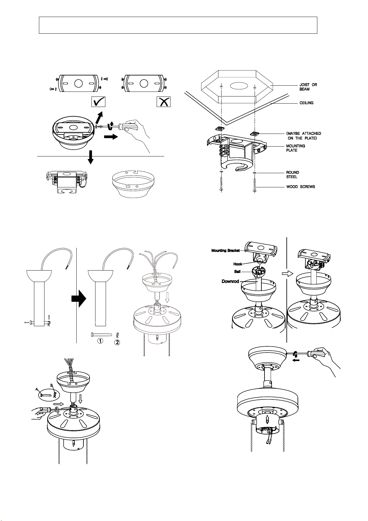
DROP ROD STYLE ASSEMBLY DIAGRAMS
Fig.5 Fig.6
Fig.7 Fig.8
8
10
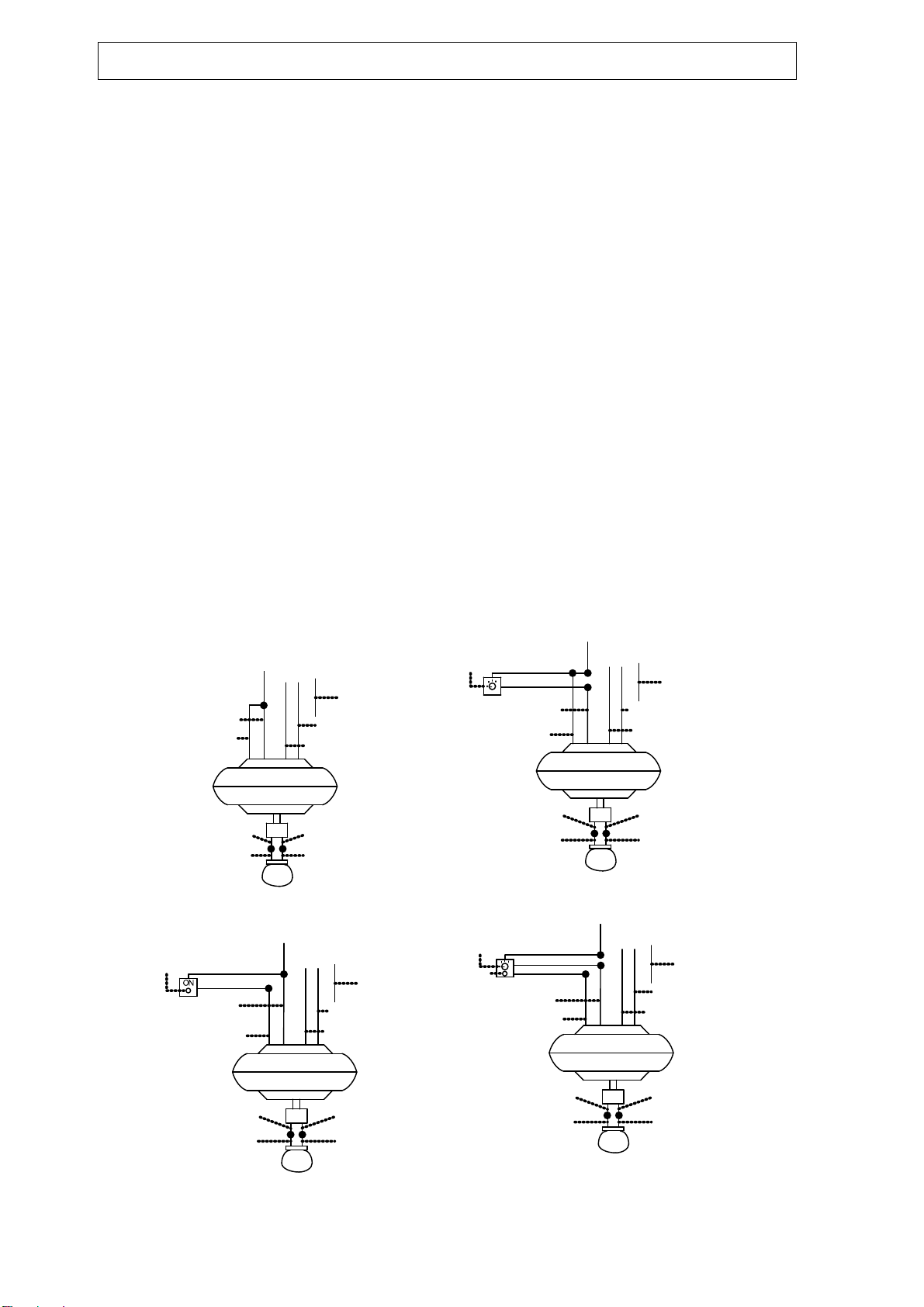
WIRING INSTRUCTIONS
NOTE:
Before installation ensure that you have all pole disconnection of the electricity supply and
that you refer to a qualified electrician to ensure that all wiring is carried out in accordance
with I.E.E. Regulations current goods practice national and local electrical codes.
Carefully read the wiring instructions and diagrams since improper installation may result
in an electrical short and void the warranty.
In most cases connect the fan motor BROWN wire to the supply wire coloured RED or
BROWN, connect the fan motor neutral BLUE wire to the neutral supply normally coloured
BLUE or BLACK, connect the mounting plate GREEN or GREEN/YELLOW earth wires to
the earth supply. SEE FIG. 9
When the light kit is attached, connect the ORANGE light wire to the supply live wire,
normally coloured RED or BROWN. If light to be independently operated from a wall
switch a separate live supply is required. SEE FIG.9
If fan is controlled independently from a wall switch. SEE FIG. 11
If a separate wall control is to be used for both fan and light please see wiring diagram
supplied with control or SEE FIG. 11.
Check to see that all your connections are tight and that no bare wires are visible of
touchable at any of the wire connectors. Except for the earth wire. Gently tuck all of the
completed wiring carefully into the canopy. If required, cut the wiring to suit.
CAUTION: THIS APPLIANCE MUST BE EARTHED. IMPORTANT: Do not connect the
motor supply cable to a dimmer switch. If a wall mounted control for the
fan is required then we recommend you contact our help-line.
9
ORANGE BLUE
BLUE
BLUE
ORANGE
BLUE
ORANGE
FROM CEILING
FROM CEILING
OR BEAN
OR BEAN
BROWN
BROWN
BROWN
BROWN
BLUB
BLUB
BLUB
BLUB
EARTHING WIRE
EARTHING WIRE
BLUE(NEUTRAL)
BLUE(NEUTRAL)
EARTH WIRE
EARTH WIRE
LOCATION
230V LIVE
230V LIVE
LIGHT SWITCH
LIGHT LEAD
ORANGE
FAN LEAD
BROWN
FIG.8 FIG.10
WALL
EARTH WIRE
FROM CEILING
OR BEAN
(NEUT RAL)
BLUE
EARTHING WIRE
BLUE(NEUT RAL)
EARTHING WIRE
OR BEAN
FROM CEILING
EARTH WIRE
230V LIVE
230V LIVE
FAN CONTROL
FAN CONTROL
SWTICH
SWTICH
LIGHT
SWTICH
LIGHT LEAD
ORANGE
FAN LEAD
BROWN
LIGHT LEAD
ORANGE
FAN LEAD
BROWN
FIG.11
FIG.9
FOR CONTROL OF FAN OR FAN AND
FOR CONTROL OF LIGHT ONLY FROM WALL SWITCH FOR CONTROL OF FAN AND LIGHT FROM WALL
FOR CONTROL OF FAN FROM
OPTIONAL LIGHT FROM FAN
BROWN FAN
LEAD
ORANGE
LIGHT LEAD
ORANGE
BLUE
ORANGE BLUE
BLUE
ORANGE BLUE
ORANGE
ORANGE

10
A. Connect the male and female plug between the light kit
and fan.
B. Install the light plate onto the switch housing using the
screws provided.
D.Install the light bulb. ( 3xE14 Max 60W, not included)
C. lnstall the light shades onto the fitter using the 3 thumb
screws. Tighten the screw to the shade firmly-do not over
tighten or use a screwdriver as this will crack the shade.
Assemble the light kit
A
B
C
D

11
Operating instructions
Having checked that all electrical connections are securely made and insulated, turn on the
power and check the operation of the fan. The pull switch on the side of the motor housing is
the selection switch for the speed function of the fan and is also the on/off function. The first
pull from the off position takes you on to the high speed; the second on to medium speed; the
third on to slow speed and the fourth pull to the off position.
The slide switch on the other side of the switch housing changes the direction of rotation of
the blades. (Remember to let the fan slow to a complete stop before changing the direction of
rotation). When looking up at the fan blades, anti clockwise rotation achieves a downward
flow of air and clockwise rotation achieves an upward movement of air.
Summer operation In warm weather a downward movement of air is more desirable as this
achieves a greater cooling effect.
Winter operation In winter a movement of air moving upwards and then back down the sides
of the room achieves a more balanced temperature throughout the room.
If a wall control or remote control system has been used refer to the accompanying leaflets
enclosed in these systems.
IMPORTANT
This fan is provided with a 3-speed pull chain type switch for choice of speeds. The
slide switch allows for forward or reverse action of the blades. Do not operate
reversing switch while fan blades are in motion. Fan must be turned off and blades
stopped before reversing blades direction.
11

12
Blade balancing
Whilst every precaution is taken at the factory to ensure your fan is of the highest quality,
imbalance may occur. This may be due to slight irregularities in the blades or blade
carriers. Further problems can be caused by deviating from these instructions.
The following procedure may help to rectify the situation.
The round plate must always be tight against the ceiling so that no movement can occur.
If the installation requires a rod style make sure that the rod is firmly locked into the boss
on top of the fan. The locking screw should be securely tightened.
Check all the blades are firmly tightened on to their carrier brackets.
Check all the carrier brackets are tightened on to the motor firmly.
Blade tracking can easily be checked by holding a yardstick or similar measure vertically
from the ceiling to the tip of the blade. Then check all blades measure the same distance
from that point. To correct slight problems in the alignment of a blade, gently bend the
carrier to bring it back in line.
Changing over two adjacent blades may correct any imbalance.
Use the universal balancing kit supplied with the fan.
Please note that drop rod styles of fans do have a slight level of movement but his is in no
way dangerous.
Care and cleaning
Periodic cleaning of your new fan is recommended particularly the blades. The plated or
painted surfaces of your fan have been sealed with a lacquer to minimize any
discoloration or tarnishing. Therefore use a soft brush or lint free cloth to avoid
scratching the surface.
The motor has permanently sealed bearings so no lubrication is necessary
Do not use water when cleaning you fan as this could damage the surfaces of the casing
and the blades and may create the possibility of an electric shock.
Product Disposal Instructions
This product has been classed as Electrical or
Electronic Equipment and should not be disposed of
with other household or commercial waste at the end
The Waste of Electrical and Electronic Equipment
(WEEE) Directive (2002/96/EC) has been put in place
to recycle products using best available precise and
minimize the impact upon the environment.
12

13
Ceiling Fan Warranty.
You must have the original purchase receipt or bill of sale to make a warranty claim. No
claim will be accepted unless proof of date of purchase is available at the time of
making the warranty claim.
Ceiling Fan Warranty Period.
The ceiling fan itself, excluding accessories such as the Remote Control Transmitter
and Receiver, is covered by a 5 year warranty. During this period, Fantasia Distribution
Ltd will, at its discretion, repair or replace defective product. During this 5 years, the
owner is responsible for labour costs incurred in removing and re-installing the fan, and
paid by Fantasia Distribution Ltd. The cost of obtaining or using special access
equipment (scissor lifts, scaffolding etc.) is specifically excluded, and it is the
responsibility of the owner to provide such equipment and have it safely installed and
operated.
Remote Control Warranty Period.
covered by a 2 year repair or replacement warranty
Balance of Warranty on Repaired or Replaced Products.
Any replaced or repaired product is covered only by the balance of the warranty
remaining on the original article.
Transfer of Warranty.
If the dwelling where the fan or remote control is installed changes hands, the balance
of the warranty passes to the new owner, providing the original bill of sale for the
product is retained by the new owner.
Warranty for the fan does not cover damage to the fan if it is moved from one dwelling
to another during the warranty period. The warranty is voided in total if the product is
sold as second hand goods.
The following is NOT covered by warranty.
1. Any damage incurred after delivery to the owner that is not caused by a fault in the
products materials or workmanship; damage from lightning or power surges;
incorrect installation; damage due to incorrect installation; water damage of any
kind; installation or use outdoors; damage arising from connection to or use with
alternative power systems (e.g. inverters, solar, etc.).
2. Ceiling fans not installed by a qualified electrician.
3. Repair of a ceiling fan used incorrectly, accidentally damaged, modified in any way
or not serviced in accordance with the maintenance instructions.
4. The cost of transporting and insuring the ceiling fan between the nearest Fantasia
Distribution Ltd agents' service depot and its normal location.
These costs must be met by the purchaser
5. Subject to any statutory provisions to the contrary, claims for damage to furniture,
carpet, walls, ceilings, foundations or any other consequential loss either directly
or indirectly resulting from a faulty ceiling fan.
6. Ceiling Fans not purchased and installed in Mainland UK.
7. A service fee will be charged where; there is nothing wrong with the ceiling fan or;
the defective operation of the ceiling fan is due to failure of electricity or; the
installation is not in accordance with Fantasia Distribution Ltd instructions and/or
applicable local regulations or; the defects have been caused by incorrect
application or abuse of the ceiling fan or; the damage has been caused by
unauthorized persons attempting to repair the fan.
13
FANTASIA DISTRIBUTION LTD.
Unit B. The Flyers Way, Westerham, Kent, TN16 1DE
Tel : (01959) 564 440 Fax : (01959) 564 829
14
MONTANA
106CM/42” or 91CM/36”
15
15

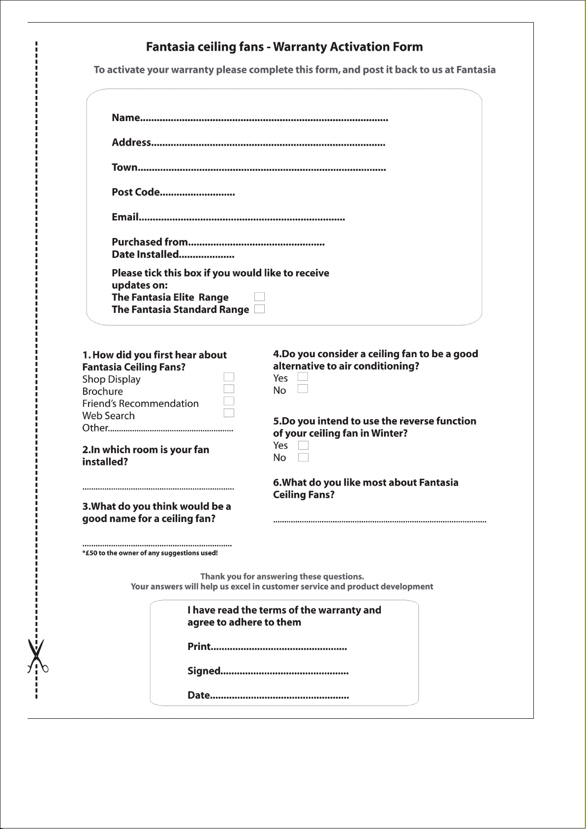
Please cut out this warranty page and send it in an envelope to the address below.
Alternatively please go to our website www.fantasiaceilingfans.com and fill in the
warranty section there.
FANTASIA DISTRIBUTION LTD.
Unit B. The Flyers Way, Westerham, Kent, TN16 1DE
Tel : (01959) 564 440 Fax : (01959) 564 829
16
MONTANA
106CM/42” or 91CM/36”
Table of contents
Other EuroFans Fan manuals


Popular Fan manuals by other brands


Hunter
Hunter Jetty installation manual

Miles Industries
Miles Industries 551DVK installation manual

Hunter
Hunter 25522 Installation and operation manual

Mammoth
Mammoth INDUSTRIAL Series instruction manual

LUCCI
LUCCI GRENADA Series Installation, operation, maintenance & warranty information

BLAUBERG Ventilatoren
BLAUBERG Ventilatoren Slim user manual

KDK
KDK N48LG Operating and installation instructions

Vents
Vents VKM EC Series user manual

Ruck Ventilatoren
Ruck Ventilatoren RS 100L Assembly instruction

Commercial Electric
Commercial Electric BF30DDCE Use and care guide

Vornado
Vornado FIT owner's guide

Ruck Ventilatoren
Ruck Ventilatoren EM E2 01 Series manual