Miles Industries 551DVK User manual

4001204-02
Designed and manufactured by / for
MILES INDUSTRIES LTD.
Columbie-Britannique, Canada
www.valorreplaces.com
Installation Manual
Direct Vent Kit—Sidewall Terminal
551DVK
Note: This kit must be installed or serviced by a qualied installer, service agency or
gas supplier. These instructions are to be used in conjunction with the main installation
instructions for the above listed heater models.
CSA approved for use only with
Valor 530, 534, 535 and Miles Fireplace MF28
Model Heaters
Kit Contents
1 Vent & Terminal
2 Wall Plates
2 Wall Shields
•
•
•

22
Installations with Horizontal Termination—Installing to Wall
See Location section in heater manual for full range of
horizontal termination applications.
Flat on Wall Installation
Cut the vent terminal pipe unit to size.
Important! The drain hole must be clearly outside
the wall.
Measure the wall thickness.
Add distance from case rear to wall.
Measure this total length along the vent unit from
where the termination cap joins the main terminal
pipes. Mark the unit.
Insert the Styrofoam support ring and push it as
close as possible to the marked position.
Cut the vent tubes squarely to length.
Make sure that all Styrofoam is removed from
the vent unit after cutting.
Free the appliance from the frame studding and slide
the appliance forward to allow the terminal to be tted.
Fit the vent unit fully over the appliance inlet and outlet
collars pushing on rmly. Make sure that the drain hole
is at the bottom—the seam will be through the notch in
the wall plates. See gure 34.
Drill through the terminal outer tube and appliance
outer collar for #6 screws. See gure 1. Make sure
that the drill does not penetrate the inner tubes.
Secure the terminal to the outer collar with two #6
thread-cutting screws supplied. See gure 1.
1.
a)
b)
c)
d)
e)
f)
2.
3.
4.
5.
Drain hole
This piece may be cut to length
Max. is 26”
5”
Important Installer Notice – Weather Sealing & Vapor Barriers
It is the installer’s responsibility to ensure that vent installations through exterior walls are caulked and weather-
proofed in such a manner as to:
Prevent rain water from entering the wall from the weather side by adequately caulking the outer vent plate to
the exterior wall surface.
Prevent moisture inside the home from penetrating into the wall structure by ensuring the inside wall plate is
adequately sealed to the inside vapor barrier.
Prevent rain water and moisture from entering the walls by sealing the joints between the outer vent tube and
the inner and outer wall plates.
We recommend the use of a high quality polyurethane sealant.
•
•
•
Figure 1

33
13”
12-1/4”
10”
10”
Drain hole
Installations with Horizontal Termination—Installing to Wall
Wall Opening
Where applicable, t all the required pipes and elbows up to the
wall. See the manufacturer’s instructions supplied with the venting
sections.
Check the wall opening position.
Make wall opening.
If the wall is constructed of solid non-combustible materials and has
no combustible surface cladding (including wood) inside or outside,
the wall plates or thimbles will not be required.
If the wall has combustible material, mark the wall for a 10” x 10”
square. If the wall is totally non-combustible (e.g. masonry block or
concrete), mark for a 7” circular hole. In both cases, the center of the
hole should line up with the center line of the horizontal vent.
Preparing Wall Plates
The wall plates are not used for 7” hole in non-combustible walls.
Bend the wall shields and screw to the inside of the wall plates with
6 thread-cutting screws per plate. See gure 2.
Bend the inner wall plate tab as shown in gure 3 so that the seam
on the terminal tube will pass clearly through the plate with the wall
shield at the top. Place the inner wall plate over the terminal unit.
Slide the appliance/terminal into the wall. Make sure that the drain
hole is at the bottom—the seam will be through the notch in the wall
plates. See gure 4.
Slide the inner wall plate up to the wall. Mark the four holes for the
wall screws. Slide the plate away.
Drill and plug the wall.
Screw the plate to the wall with four screws provided.
Bend the outer wall plate tab as shown in gure 4.
Place the outer wall plate over the terminal unit. Slide the wall plate
up to the wall. Mark the four holes for the wall screws. Slide the
plate away.
Drill and plug the wall.
Screw the plate to the wall with four screws provided. See gure 4.
Re-position the appliance so that it is suitable for the wall nish.
Terminals—Installing to Wall
Unless the wall is totally non-combustible, t wall thimbles. Install as
detailed in the manufacturer’s instructions supplied with the pipes.
Sidewall vent terminations within 7’ of grade require a terminal
guard when used with a 551DVK. See gure 3a.
•
•
•
1.
2.
3.
4.
5.
6.
7.
8.
9.
10.
11.
13-1/4”
8”
16-3/4”
Figure 2
Figure 3
Figure 4
Figure 3a Terminal Guard Figure 3b Terminal
10” (254 mm)
10” (254 mm)
Align the vent
center to the
center of the
frame
Square opening
Bend
this tab
towards
wall
Bend
this tab
towards
wall
Inside Wall Plate
Outside Wall Plate

44
Designed and Manufactured by / for
Miles Industries Ltd.
190 – 2255 Dollarton Highway, North Vancouver B.C, CANADA. V7H 3B1
Tel. (604) 984-3496 Fax (604) 984-0246
www.valorreplaces.com
© Copyright Miles Industries Ltd., 2008
#Description Number Qty
1Vent Pipe & Terminal 569349 1
2 Wall Shield 569369 2
3Wall Plate 569359 2
Repair Parts List

55
4001204-02
Conçu et fabriqué par / pour
MILES INDUSTRIES LTD.
Columbie-Britannique, Canada
www.foyervalor.com
Guide d’installation
Sortie d’évacuation horizontal au mur
551DVK
Homologué par la CSA pour utilisation seulement avec
les foyers Valor 530, 534, 535 et les foyers Miles Fireplaces MF28
Contenu du kit
1 Conduit et sortie
2 Plaques murales
2 Écrans de protection du mur
•
•
•
Note : Ce kit doit être installé ou réparé par un installateur qualié, une agence de service certiée
ou un fournisseur de gaz. Ces instructions doivent être utilisées conjointement avec les instructions
d’installation des modèles de foyers indiqués ci-dessus.

66
Installations avec sortie d’évacuation horizontale
Voir la section Emplacement dans le guide d’installation
du foyer pour connaître les congurations d’installations
horizontales possibles.
Installation au mur
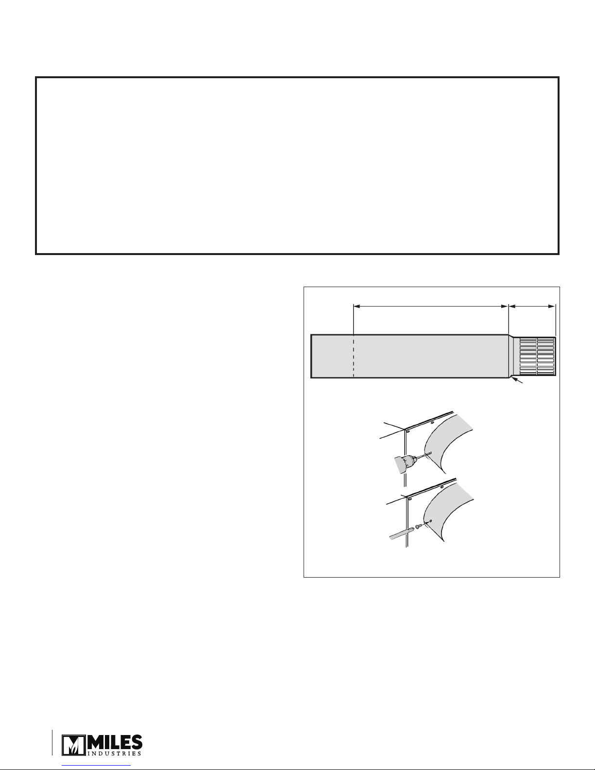
Coupez l’extrémité du conduit à la longueur désirée—
maximum 26 po. Schéma 1.
Important! L’orice de drainage doit être clairement
hors du mur.
Mesurez l’épaisseur du mur.
Ajoutez la distance entre la boîte de foyer et le mur.
Mesurez la longueur totale calculée sur le conduit jusqu’au capuchon de
sortie. Marquez le conduit.
Insérez le support circulaire de styromousse et poussez-le le plus près
de la position marquée.
Coupez le conduit également à la position marquée.
Assurez-vous d’enlever le support en styromousse aussitôt la
coupe complétée.
Libérez l’appareil et glissez-le hors de la charpente pour permettre
l’installation du conduit.
Couvrez complètement les buses d’évent de l’appareil avec le conduit en le
poussant fermement sur les buses. Assurez-vous que l’orice de drainage
soit orienté vers le bas—le joint du conduit doit passer à travers l’encoche
des plaques murales. Schéma 4.
Percez les parois extérieures du conduit et de la buse d’évent pour utilisation de vis no6. Schéma 1. Assurez-vous
que la perçeuse ne pénètre pas les parois intérieures.
Fixez le conduit à la buse extérieure avec deux vis autotaraudeuses no6 fournies. Schéma 1.
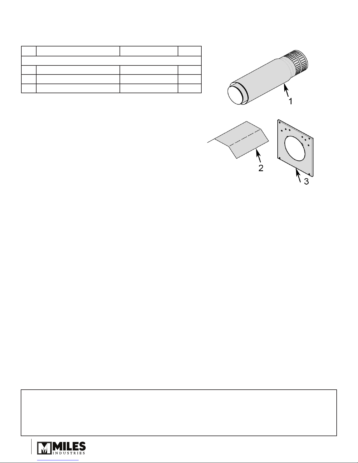
1.
a)
b)
c)
d)
e)
f)
2.
3.
4.
5.
Orifice de
drainage
Ce conduit peut être coupé
Maximum 26”
5”
Schéma 1
Avis à l’installateur – Isolation du conduit d’évacuation
L’installateur est responsable de s’assurer que les installations d’évacuation à travers les murs extérieurs soient
étanches et à l’épreuve des conditions atmosphériques de façon à :
Prévenir l’inltration d’eau de pluie dans le mur extérieur en appliquant un joint d’étanchéité entre le pourtour de
la plaque murale extérieure et la surface du mur extérieur.
Prévenir la pénétration de l’humidité de la maison dans le mur en appliquant un joint d’étanchéité entre le
pourtour de la plaque murale intérieure et le pare-vapeur.
Prévenir l’inltration d’eau de pluie et la pénétration de l’humidité en appliquant un joint d’étanchéité entre la
paroi extérieure du conduit d’évacuation et les plaques murales intérieure et extérieure.
Nous conseillons l’utilisation d’un produit d’étanchéité à base de polyuréthane de haute qualité.
•
•
•
Ouverture du mur
Pour déterminer l’emplacement de l’ouverture du mur, placez tous les conduits
d’évacuation et accessoires de l’appareil jusqu’au mur. Consultez les directives
d’installation fournies avec chaque conduit et accessoire d’évacuation.
Vériez la position pour l’ouverture du mur.
Ouvrez le mur.
Les plaques murales ou fourreau ne sont pas requis dans le cas d’un mur
plein fabriqué d’un matériau incombustible et non-recouvert de matériau de
parement combustible (incluant le bois) à l’intérieur ou à l’extérieur.
Si le mur est fabriqué de matériaux combustibles, marquez le mur pour un
trou carré de 10 po sur 10 po (254 mm sur 254 mm). Si le mur est entièrement
incombustible (i.e. blocs de maçonnerie ou béton), marquez le mur pour un
trou rond d’un diamètre de 7 po (178 mm). Dans les deux cas, le centre du trou
devra être aligné avec le centre du conduit d’évacuation horizontal.
•
•
•
10” (254 mm)
10” (254 mm)
Alignez le centre
de l’évent au
centre du trou
Ouverture carré

77
Préparation des plaques murales
Les plaques murales ne sont pas nécessaires pour un trou de 7 po
(178 mm) dans un mur incombustible.
Pliez les écrans de protection du mur et vissez-les à l’intérieur des
plaques murales avec 6 vis autotaraudeuses fournies par plaque.
Schéma 2.
Pliez la languette de la plaque murale intérieure de façon à ce que
le joint du conduit d’évacuation passe librement dans la plaque
murale, sous l’écran de protection. Schéma 3. Placez la plaque
murale intérieure sur le conduit d’évacuation.
Glissez l’appareil munie du conduit dans le mur. Assurez-vous de
l’orice de drainage du conduit est orienté vers le bas—le joint du
conduit passera dans l’encoche des plaques murales. Schéma 4.
Glissez la plaque murale intérieure au mur. Marquez le mur
des points de xations aux quatre coins. Glissez la plaque vers
l’appareil.
Percez le mur et insérez des chevilles murales.
Replacez la plaque au mur et vissez-la en place avec 4 vis
fournies.
Pliez la languette de la plaque extérieure. Schéma 3.
Placez la plaque extérieure sur le conduit d’évacuation. Glissez la
plaque au mur. Marquez le mur des points de xation aux quatre
coins. Enlevez la plaque.
Percez le mur et insérez des chevilles murales.
Remettez la plaque sur le conduit et glissez-la à nouveau au mur.
Vissez-la avec les quatre vis fournies. Schéma 4.
Replacez l’appareil de façon appropriée pour la nition du mur.
Sortie—installation au mur
À moins d’un mur entièrement incombustible, installez un fourreau tel
qu’indiqué dans les directives d’installation fournies avec le kit.
Si la sortie 551DVK se trouve à moins de 7 pi (2,13 m) du sol,
installez un grillage de protection sur la sortie d’évacuation.
Schéma 3a.
1.
2.
3.
4.
5.
6.
7.
8.
9.
10.
11.
13-1/4”
8”
16-3/4”
Schéma 2
13”
12-1/4”
10”
10”
Orifice de
drainage
Schéma 4
Schéma 3a Grillage de
protection
Schéma 3b Sortie
Schéma 3
Pliez
cette
languette
vers le
mur
Pliez cette
languette
vers le
mur
Plaque murale intérieure
Plaque murale extérieure
12-1/4”
5” - 6”
en saillie
6-5/8” dia.
13”
Installations avec sortie d’évacuation horizontale

88
Conçu et fabriqué par / pour
Miles Industries Ltd.
190 – 2255 Dollarton Highway, North Vancouver C.-B., CANADA. V7H 3B1
Tél. 604-984-3496 Téléc. 604-984-0246
www.foyervalor.com
© Tous droits réservés Miles Industries Ltd., 2008
#Description Numéro Qté
1 Conduit et sortie 569349 1
2Écran de protection du mur 569369 2
3Plaques murale 569359 2
Liste de pièces
Table of contents
Languages:
Popular Fan manuals by other brands

ARDES
ARDES AR5BL2 Instructions for use

Sulion
Sulion MAKI manual

Fanimation
Fanimation Torrento FP920 Series Specification sheet

Skov
Skov DA 600 Mounting guide

Panasonic
Panasonic Whisper Value-Lite FV-08VSL1 installation instructions

Mitsubishi Electric
Mitsubishi Electric EF-20UYS-UL Installation instructions manual