Mammoth INDUSTRIAL Series User manual
CAUTION
READ INSTRUCTIONS CAREFULLY FOR SAFE
INSTALLATION AND FAN OPERATION.
INDUSTRIAL SERIES
INSTALLATION • OPERATION • MAINTENANCE • WARRANTY INFORMATION
INSTRUCTION MANUAL
SKU 211400 & 211401

2
SAFETY PRECAUTIONS
CONGRATULATIONS ON YOUR PURCHASE
Congratulations on your purchase of a Mammoth Fan. The Mammoth fan range features world class Permanent Magnetic
Synchronous (PMSM) technology and precision-led aeronautical design in Mammoth Proportions.
With energy efficiency, design and ultimate performance in mind, Mammoth Fans have developed the latest in High Volume Low
Speed (HVLS) ceiling fans for large residential, commercial and industrial spaces to suit Australian conditions.
Whether it is large outdoor alfresco spaces, industrial warehouses, agricultural buildings, gymnasiums, halls or public spaces,
Mammoth Fans has the perfect solution for your project. With market leading features of supreme efficiency, low noise and minimal
maintenance, easy installation and advice backed by a 5 year warranty, Mammoth Fans are here to keep you cool.
The Mammoth fan you have purchased is a sophisticated electrical device, all care must be taken to ensure the fan is kept clean and
not mistreated as issues arising will not be covered under the warranty.
1. Always ensure the power is OFF before performing installation, maintenance, cleaning or making any adjustment to the fan.
2. Must be assembled and installed by a licensed electrician.
3. All wiring and installation of the fan must adhere to the latest local and national wiring rules. eg. AS/NZS 3000 Electrical
installations.
4. The appliance is not intended for use by persons (including children) with reduced physical, sensory or mental capabilities,
or lack of experience and knowledge, unless they have been given supervision or instruction concerning the use of the
appliance by a person responsible for their safety.
5. Children should be supervised to ensure that they do not play with the appliance.
6. An all-pole disconnection switch must be incorporated into the fixed wiring, in accordance with local wiring rules.
7. The structure to which the fan is to be mounted must be capable of supporting 2 times the weight of the
product and its own structural loading. Check with a structural engineer if unsure.
8. Please do not alter the structure of the install site without prior advice of a structural engineer.
9. The fan should be mounted so that the blades are at least 3.5m above the floor.
10. This fan is suitable for covered alfresco use.
11. The Mammoth Fan must be installed with the electrical control box supplied.
12. During installation, adjustment and cleaning ensure the blades are not bent as this
will drastically impact the performance of the fan
13. Please make sure the fan’s input voltage and supply voltage are the same before cut-in the power.
14. Please do not open the electrical control box without first isolating the power as electrical shock may occur.
15. Please do not operate the fan if you notice any damage or noises to/from the fan
16. The control box is a sophisticated controller designed specifically for the Mammoth Fans.
No modifications to the controller are permitted and failure to follow this advice could cause injury or death.
17. Within the electrical control box is a high-voltage storage capacitor. When you operate the fan, please wait for
3 minutes to let the voltage discharge to prevent electric shock.
18. Ensure sufficient clearance around the fan and NO obstructions before starting up the fan. Failure to do so will cause
significant damage and will not be covered under the warranty.
19. Ensure not to cut off the power to the fan while it is in operation. Please stop the fan first then isolate the power.

Mammoth Fans INDUSTRIAL SERIES | 3
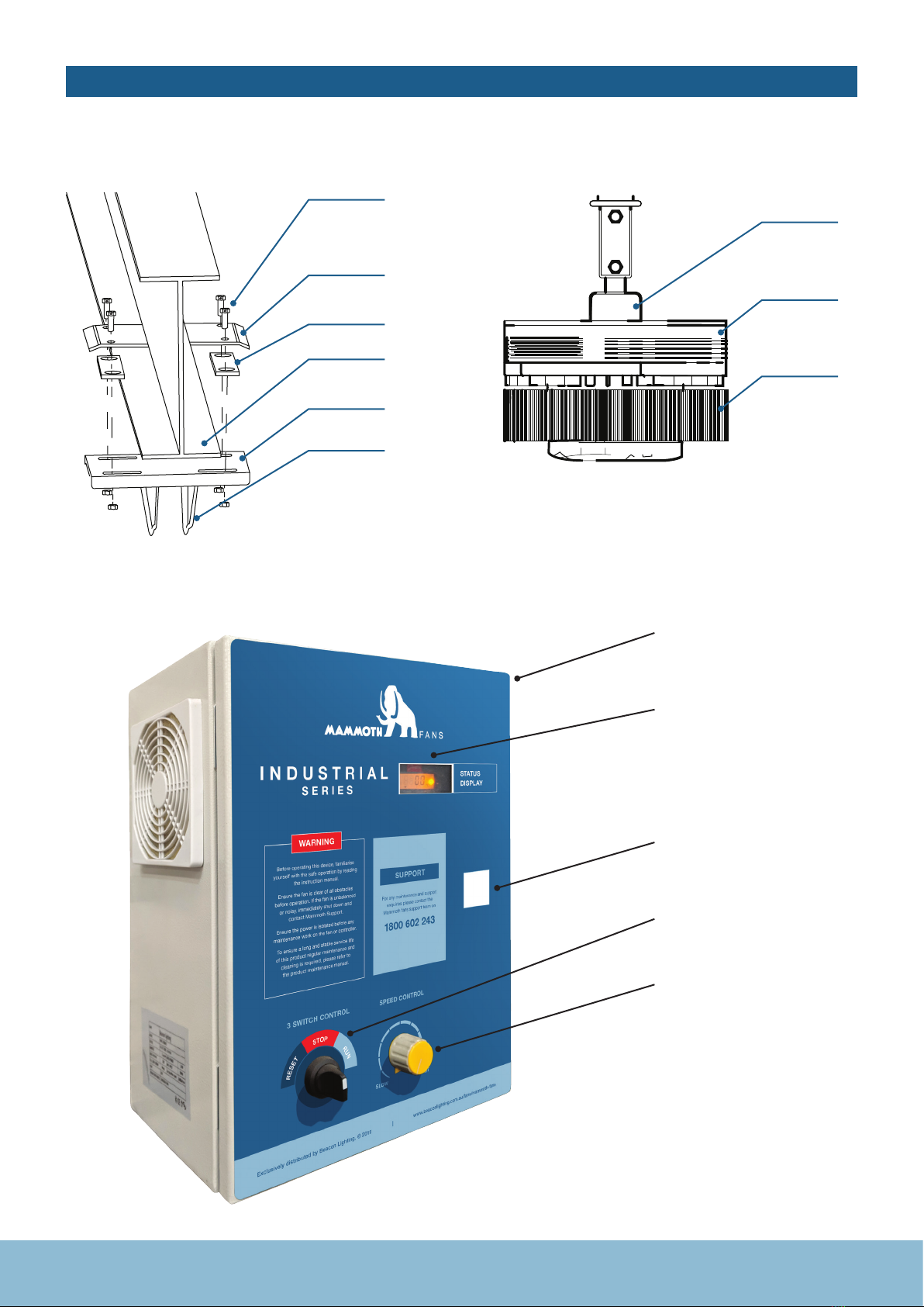
PARTS LIST
1. General parts
1. Clamp plate
2. I-beam steel structure
3. Extension tube
4. Turnbuckle and clamps
5. PMSM Motor
6. Connector
7. Steel wire
8. Blade retainer
9. Fan blade
10. Winglet
1
7
6
8
3
4
5
10
9
2
4
PARTS LIST
3. Control unit
2. Standard component parts
Control cabinet
stator shaft
clamp plate
I-beam
top plate
extension rod connector
pressure plate
shim
rotor disk
sunflower
heat sink
Display window
Speed controller
Switch
Cabinet key lock

Mammoth Fans INDUSTRIAL SERIES | 5
4. Packing list
Motor crate
PARTS LIST
NO. DESCRIPTION NO. DESCRIPTION
1PMSM motor system 8O Ring
2Control Box 9Steel Wire
3Top Plate 10 Fastener
4Shim 11 Cable
5Clamp Plate 12 Winglet
6Blade retainer
7Turnbuckle
CASE NO DIMENSIONS
( LxWxHmm )
Volume
( m3 )
Gross weight
( kg ) Remark
1 940 x 580 x 640 0.35 160 Main body crate
PACKING SPECIFICATION
COMMERCIAL
SERIES
Exclusively distribu ted by Beacon Lighting © 2019
SLOW FAST
SUPPORT
WARNING
Please read the instruction
manual before operation.
Ensure the fan is clear of
all obstructions before operatio n.
If the fan is unbalanced or noisy,
immediately shut down and
contact Mammoth Support.
Ensure the power is isolated
before any maintenance work is
carried out on the fan or controlle r.
NOTE
Always start the fan on low speed.
For any maintenance
enquiries please contact the
Mammoth Fans support team
1800 602 243
9543BMammoth COMMERCIAL (Diamond) Control Box sticker 176x276mm.indd 1 21/5/19 3:07pm
1.
2.
4.
3.
5.
6.
10.
8.
9.
11.
12.
7.

6
PARTS LIST
NO. DESCRIPTION
1Fan Blade
2Extension Tube
CASE NO DIMENSIONS
( LxWxHmm )
Volume
( m3 )
Gross weight
( kg ) Remark
2 3650 x 420 x 400 0.61 130 Fan blade carton
PACKING SPECIFICATION
PACKING DETAILS
1. 2.
Mammoth Fans INDUSTRIAL SERIES | 7
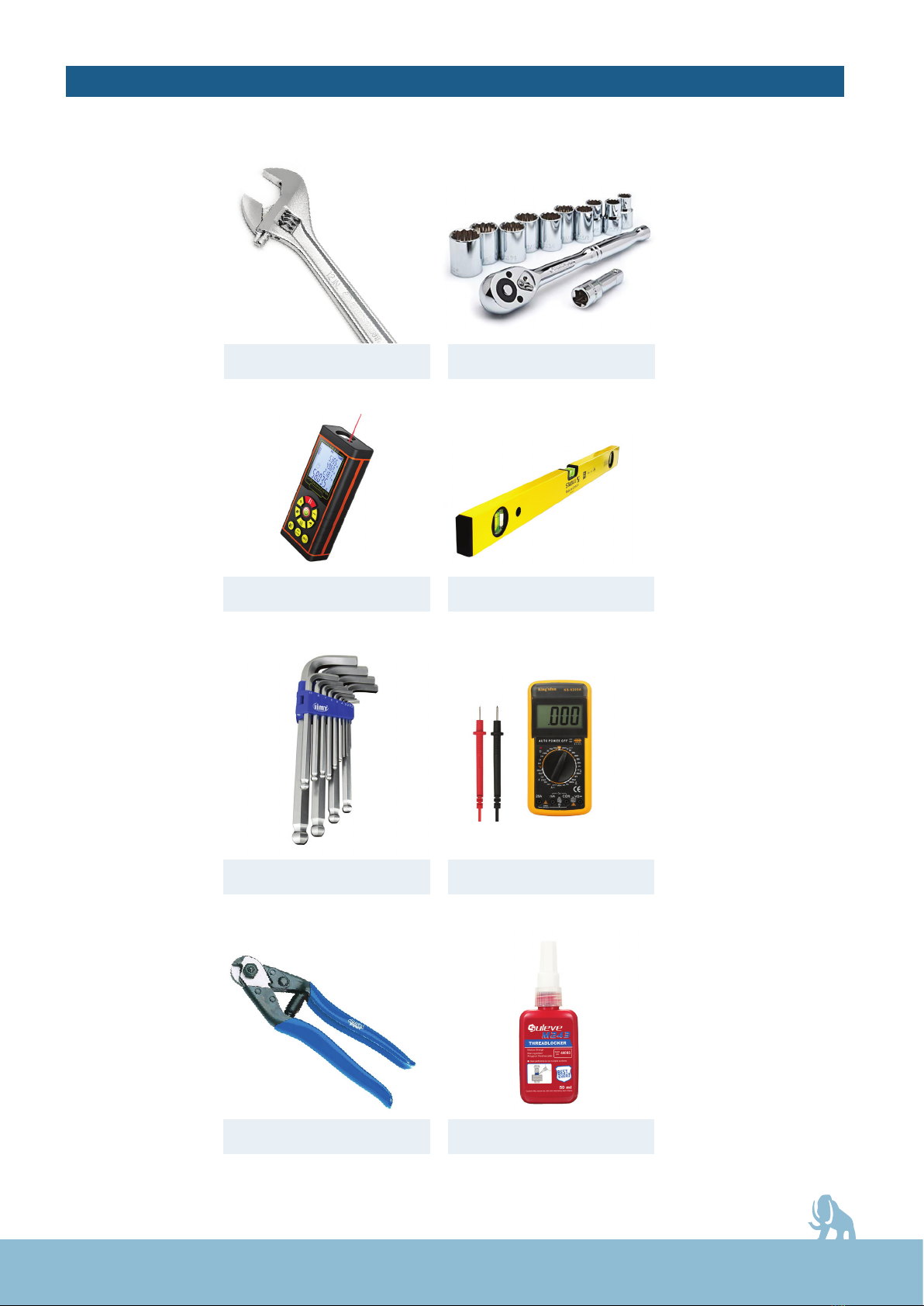
5.Required Installation tools
PARTS LIST
ADJUSTABLE WRENCH
LASER DISTANCE MEASURE
ALLEN KEYS
WIRE-CUTTER
SOCKET WRENCH
LEVEL
MULTIMETER
SCREW GLUE
8
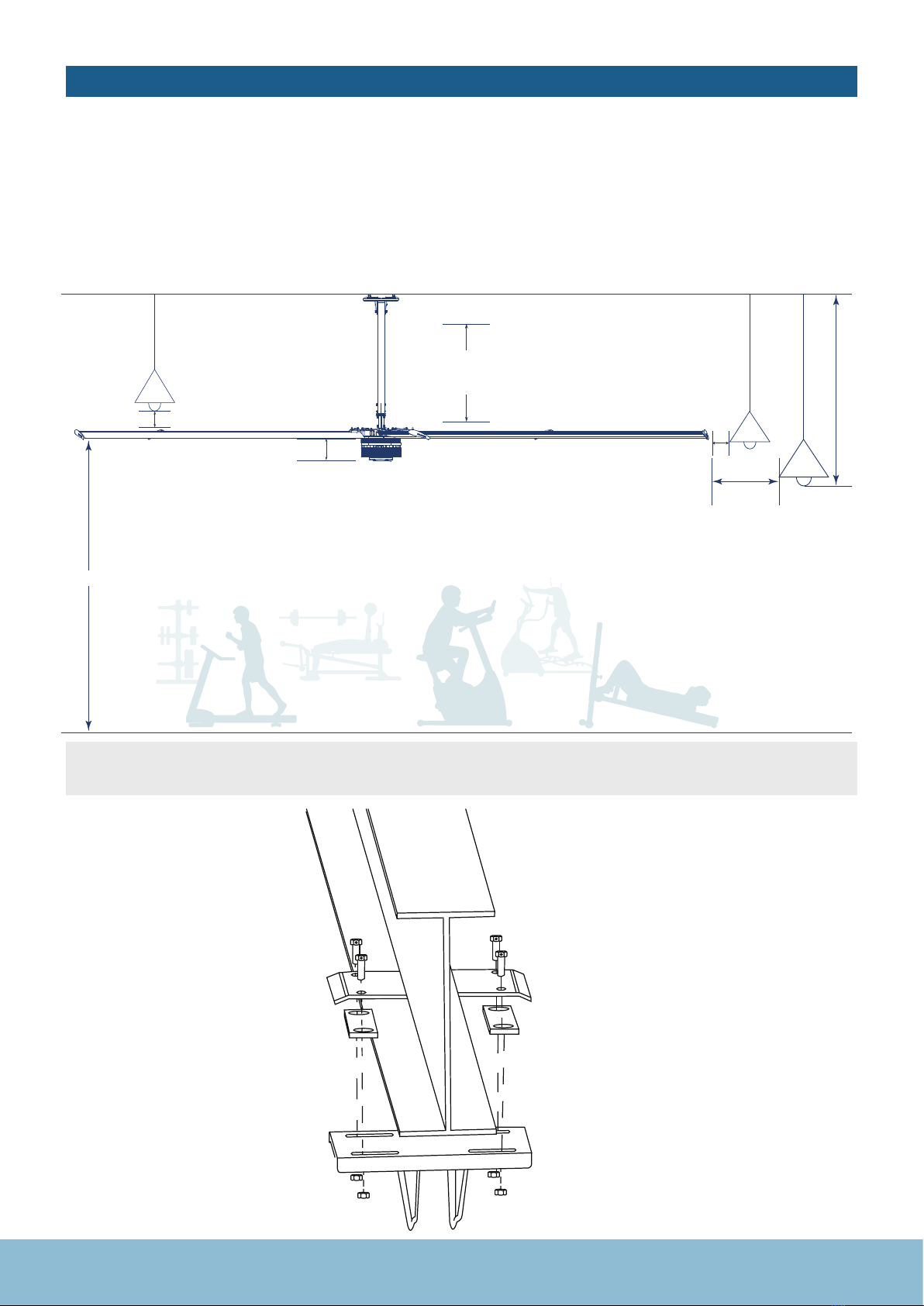
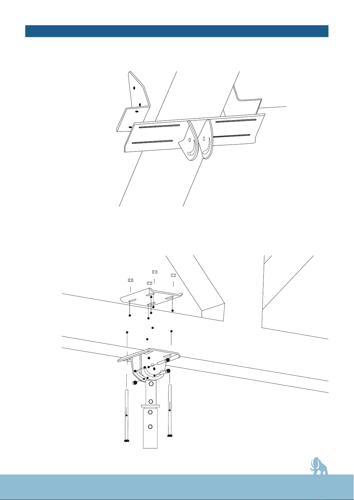
INSTALLATION REQUIREMENT
1.Roof installation requirement
The Mammoth Fan must be installed in a location so that the blades have enough space between the and the nearest objects or
walls (Refer to the below diagram for detail spacing requirement).
Secure the hanging bracket to the ceiling joist or structure with bolts & nuts provided. Ensure there are 3 – 4 threads left on the
bolt after tightening the nut.
The structure to which the fan is to be mounted must be capable of supporting 2 times the weight of the product and its own
structural loading. Check with a structural engineer if unsure.
2. I-Beam Steel structure
(Included as standard)
Extension tube
0 - 5.2M
Driving unit
0.36M ≥0.5M + R if the object is
lower than the fan blade
≥0.5M if the object is at the
same level as the fan blade
≥0.5M if the object is
above the fan blade
Roof
R
Ground
≥3.5M
NOTE: be cautious of items like light fittings which may swing into the
path of the spinning fan, ensure appropriate clearance is maintained.
Mammoth Fans INDUSTRIAL SERIES | 9
INSTALLATION REQUIREMENT
3. Concrete structure
(This accessory sold separately)
4. Steel, concrete or
Timber beam structure
(This accessory sold separately)
1. PREPARATION Carefully unload and position the fan on the ground in a location
that won’t be impacted by ladders, scissor lifts or personnel.
2. PLAN Carefully plan and consider the following information
1. Installation point
2. Installation height
3. Whether there are obstacles (such as, light, cable, fire protection, cameras, forklift access etc.)
4. The position of the control box
5. The input power and design of your electrical layout
6. Traction steel wire position
3. SAFETY Ensure power is isolated to the area that you are working. Ensure safe practices are followed in
regards to working at heights and lifting heavy equipment. Follow appropriate guidelines and
regulations in your region.
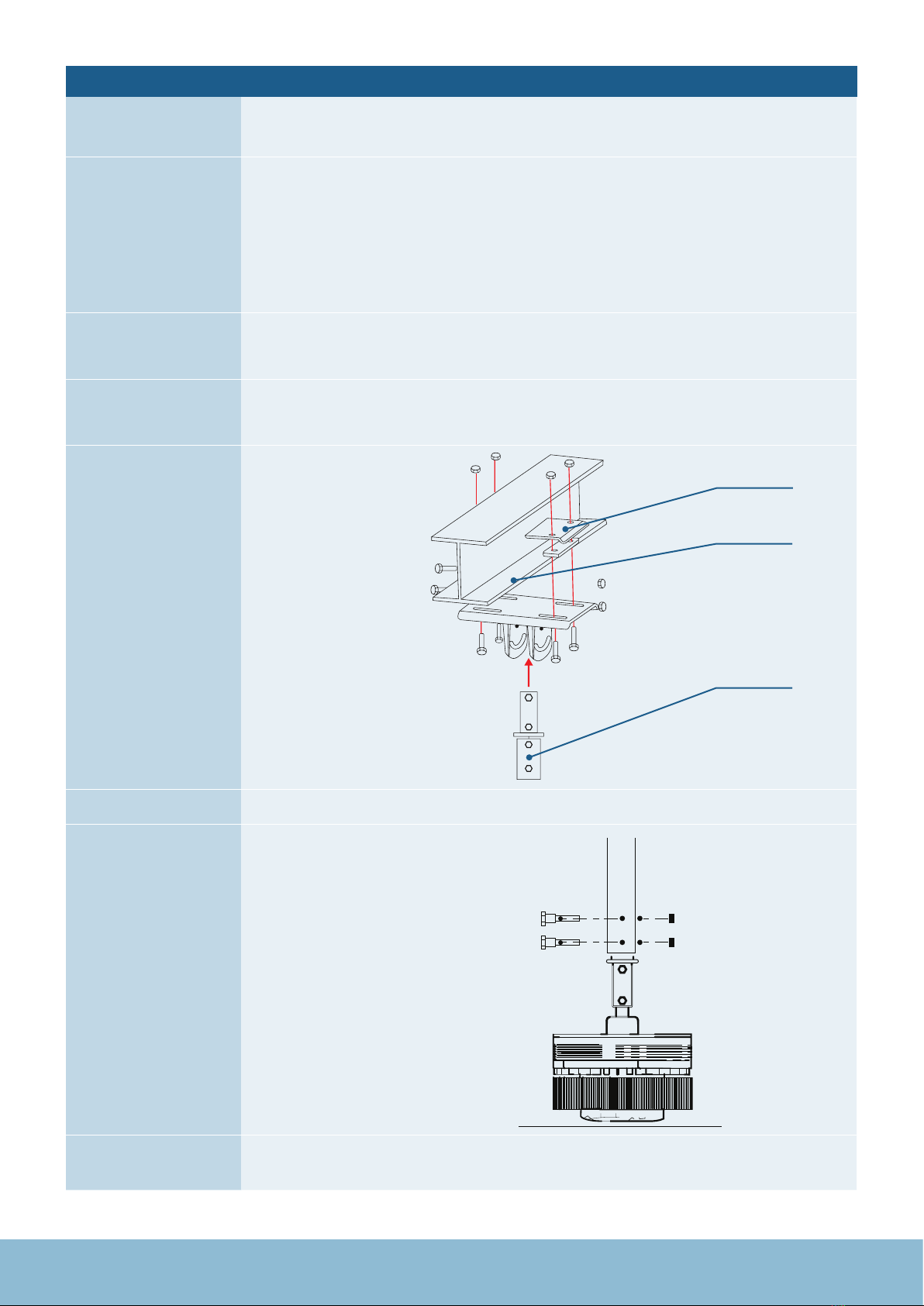
4. TOP PLATE Fastening the top plate to the H beam, ensuring a tight connection between the beam and the
plate. Screw glue (Loctite or similar) should be used.
5. EXTENSION TUBE
6. POWER CABLE Ensure you have sufficient length of the cable coming from the extension tube.
7. MAIN BODY
Ensure bolts are horizontal
before tightening the main body
to the extension tube.
8. WIRING Make the appropriate electrical connection to the fan body,
ensure neat and tight connections are completed.
10
FAN INSTALLATION
clamp plate
I-beam
extension tube
Mammoth Fans INDUSTRIAL SERIES | 11
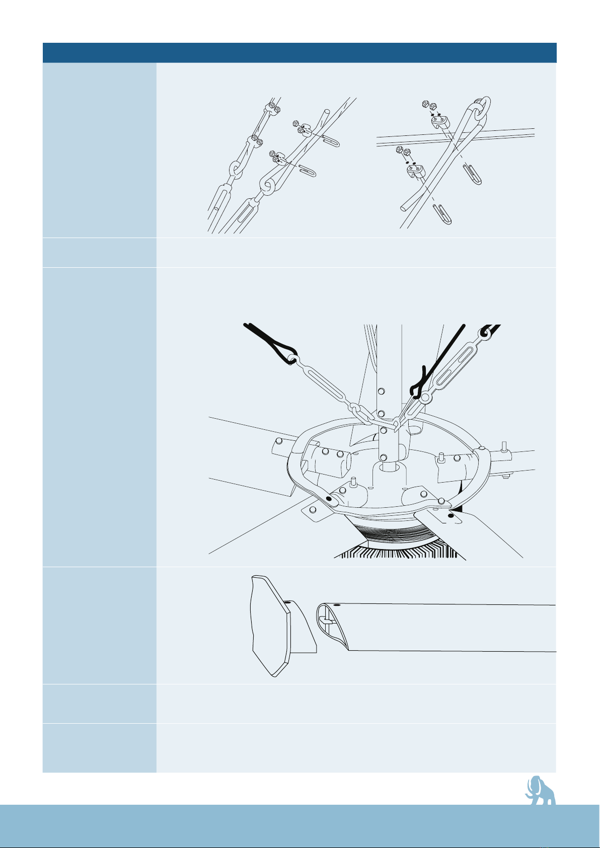
FAN INSTALLATION
9. STEEL WIRING Important – support wires should be evenly spaced in 4 opposing directions to evenly
distribute any stress and movement. Wire clamps should be secure and glued with screw
glue (Loctite or similar)
10. POWER CABLE Wiring should be to local regulations
11. FAN BLADES Fan blades should be mounted one after the other in opposites to each other, two people
will be required to effectively mount and tighten the fan blades and safety support screws.
This procedure must be done while the fan motor is mounted on the ceiling. Trying to
compete this on the floor then mounting the fan will cause damage to the blades.
12. FAN BLADE TIP
INSTALLATION
Fan Blade Tip
13. CONTROL
SYSTEM
The height from floor to the bottom of the control box should be around
1.2 meters and in a safe and practical position
14. WIRING Distinguish the input and output, also make sure the ground wire is in place,
wire to local wiring standards.
12
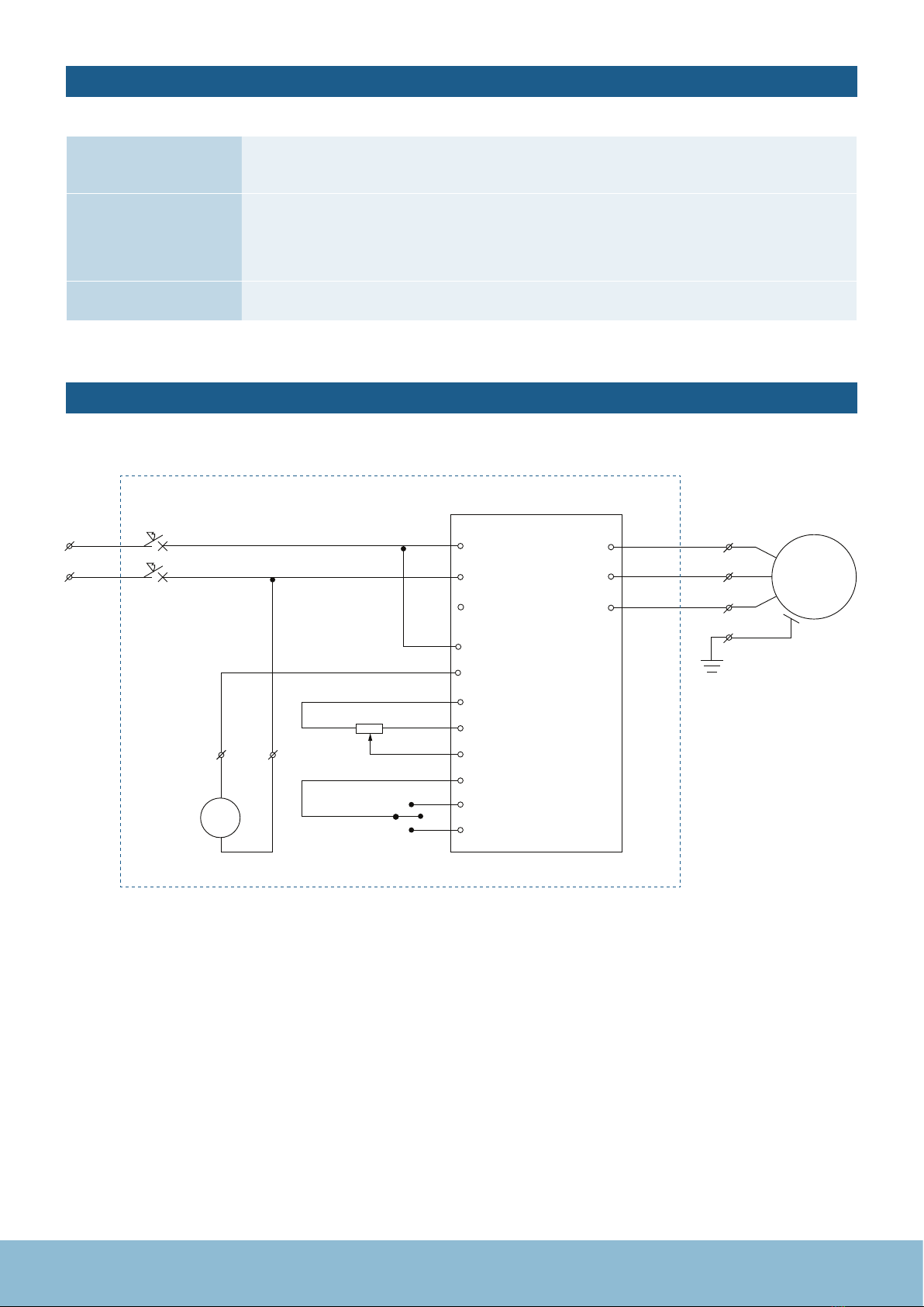
FAN INSTALLATION
CIRCUIT DIAGRAM
15. DEBUGGING Each Mammoth fan is tested prior to leaving the factory, if there seems to be a problem
double check all electrical connections, and contact the Mammoth support team.
16. COMMISSIONING Use a spirit level and ensure blades are level before switching on. Run the fan for 15mins
and observe, is it spinning in the correct direction (anti-clockwise for summer), listen for any
abnormal noise, ensure there is no movement in the support cables. Check the current is
within the rated range.
17. HANDOVER Ensure the customer is instructed on how to operate and isolate the fan
FAN
U/T1 U
V
W
R/L1
S/L2
T/L3
01
03
55/GND
55
S2
R2-1
50
53
12
18
27
50/+10V OUT
R1
SA1
53/0-10V AIN
12/+12V OUT
18/Start
27/Reset
V/T2
W/T3
Breaker
Inverter
M
CONTROL BOX

Mammoth Fans INDUSTRIAL SERIES | 13
SPECIFICATION OF PARAMETERS FOR CONTROL SYSTEM
RoHS
US
CU
®L
Setup 1
Menu
Status Quick
Menu
Main
Menu
On
Warm
Alarm
Hand
On
Off
Reset
OK
Auto
On
B
a
c
k
value
numeric display
unit
selected menu
navigation keys
potentiometer (LCP 12)
operation keys
Hz

14
WARNING
Please read the instruction
manual before operation.
Ensure the fan is clear of all obstructions
before operation. If the fan is unbalanced
or noisy, immediately shut down
and contact Mammoth Support.
Ensure the power is isolated before
any maintenance work is carried
out on the fan or controller.
To ensure a long and stable service life
of this product regular maintenance and
cleaning is required, please refer to
the product maintenance manual.
NOTE: Always start the fan on low speed.
Function switch on control box this feature sets the device to reset – stop – run operating process is as follows
1. Ensure there are no obstructions or potential danger before switching the fan on
2. Turn the speed dial to the minimum setting
3. Turn the control dial from Stop to Run position
4. After the fan starts rotating, adjust the speed control to your desired level.
Shutdown Process
1. Turn the control dial from Run to Stop
OPERATING INSTRUCTION
Speed controller
Switch

Mammoth Fans INDUSTRIAL SERIES | 15
CLEANING & MAINTENANCE
TECHNICAL INFORMATION
Cleaning & maintenance
1. Please ensure the power to the Mammoth fan is isolated before completing any cleaning and maintenance work.
Also ensure you follow all local regulations in regards to safe working at heights practices. Periodic cleaning of your
ceiling fan is the only maintenance required. Use a soft brush or lint free cloth to avoid scratching the paint finish.
2. A damp cloth can be used to wipe down the blades, however ensure not to allow excess water to enter any wiring
connections, this could damage the fan and cause a safety issue.
3. Ensure that the fitting does not come in contact with any organic solvents or cleaners.
4. The motor has a permanently lubricated ball bearing which does not require maintenance or re-oiling.
SKU# 2114 0 0 2114 01
Model No. HVLS-D6AAA73 HVLS-D6AAA55
Diameter 7. 3 m 5.5m
Rated voltage 220-240V~ 50Hz 220-240V~ 50Hz
Rated power 1800W 1800W
Full load current 8A 8A
Max. Speed 57RPM 70RPM
Air volume at max. speed 14800m3/min 13350m3/min
Climate class T – Tropical T – Tropical
Weight 135kg 113 kg

16
NO. Description Warning Alarm Trip
Lock Error Cause of Problem
2Live zero error X X
Signal on terminal 53 or 60 is less than 50% of
value set in 6-10 Terminal 53 Low Voltage, 6-12
Terminal 53 Low Current and 6-22 Terminal 54
Low Current.
4Mains phase loss1) X X X Missing phase on supply side, or too high
voltage imbalance. Check supply voltage.
7 DC over voltage1) X X Intermediate circuit voltage exceeds limit.
8DC under voltage1) X X Intermediate circuit voltage drops
below “voltage warning low” limit.
9Inverter overloaded X X More than 100% load for too long.
10 Motor ETR over temperature X X Motor is too hot due to more than 100%
load for too long.
11 Motor thermistor over temperature X X Thermistor or thermistor
connection is disconnected.
12 Torque limit XTorque exceeds value set in either par. 4-16 or 4-17.
13 Over current X X X Inverter peak current limit is exceeded.
14 Earth fault X X X Discharge from output phases to ground.
16 Short circuit X X Short-circuit in motor or on motor terminals.
17 Control word timeout X X No communication to frequency converter.
25 Brake resistor short-circuited X X Brake resistor is short-circuited,
thus brake function is disconnected.
27 Brake chopper short-circuited X X Brake transistor is short-circuited,
thus brake function is disconnected.
28 Brake check X Brake resistor is not connected/working.
29 Power board over temp X X X Heat-sink cut-out temperature has been reached.
30 Motor phase U missing X X Motor phase U is missing. Check the phase.
TROUBLESHOOTING
Common causes for malfunctioning operation
1. The external power supply of the control box is not within the range appropriate for the controller
2. Ensure there is power to the controller box, turn speed dial to Minimum setting (SLOW), Turn the control dial to Run.
If this doesn’t work return the control dial to reset, then return dial to Stop, and finally to Run.
3. If on start up you notice any unusual sounds coming from the fan or the controller immediately return the control dial to Stop
and contact the Mammoth Support team.
4. Equipment damage due to the improper use is not covered by the warranty. Mammoth Fans will not be responsible for
personal injuries and equipment damages for failure to comply with the contents of this manual.
Explanation of the error codes on control unit:
Mammoth Fans INDUSTRIAL SERIES | 17
TROUBLESHOOTING
NO. Description Warning Alarm Trip
Lock Error Cause of Problem
31 Motor phase V missing X X Motor phase V is missing. Check the phase.
32 Motor phase W missing X X Motor phase W is missing. Check the phase.
38 Internal fault X X Contact local Danfoss supplier.
44 Earth fault X X Discharge from output phases to ground.
47 Control voltage fault X X 24 V DC may be overloaded.
51 AMA check Unom and Inom X Wrong setting for motor voltage and/or motor current.
52 AMA low Inom X Motor current is too low. Check settings.
59 Current limit XVLT overload.
63 Mechanical Brake Low XActual motor current has not exceeded “release brake”
current within “start delay” time window.
80 Drive Initialised to Default Value XAll parameter settings are initialized to default settings.
84 The connection between drive
and LCP is lost XNo communication between
LCP and frequency converter.
85 Button disabled X See parameter group 0-4* LCP
86 Copy fail XAn error occurred while copying from
frequency converter to LCP or vice versa.
87 LCP data invalid X Occurs when copying from LCP if the LCP contains
erroneous data - or if no data was uploaded to the LCP.
88 LCP data not compatible X
Occurs when copying from LCP if the data
are moved between frequency converters
with major differences in software versions.
89 Parameter read only X Occurs when trying to write to a read-only parameter.
90 Parameter database busy XLCP and RS485 connection are trying
to update parameters simultaneously.
91 Parameter value is not valid in
this mode XOccurs when trying to write
an illegal value to a parameter.
92 Parameter value exceeds
the min/max limits X Occurs when trying to set a value outside the range.
nw
run Not While RUNning XParameter can only be changed
when the motor is stopped.
Err. A wrong password was entered X Occurs when using a wrong password for
changing a password-protected parameter.
1) These faults may be caused by mains distortions. Installing Danfoss Line Filter may rectify this problem.

18
WARRANTY
WARRANTY HOTLINE- 1800 602 243
THIS WARRANTY IS VALID IN AUSTRALIA ONLY
In the event of service being required, please call the Mammoth Fan Support Hotline on 1800 602 243 between
9am & 5pm (EST) Monday to Friday.
Please make sure you have all the Mammoth Fan details filled out at the end of the manual before making the call.
Every Mammoth fan is thoroughly inspected and tested before being released for sale. In addition to any warranty rights or
conditions under statutory regulations, Mammoth Fans warrant all of its ceiling fans against defective workmanship and faulty
materials for 5 years from the date of purchase. Mammoth Fans undertake, at its option, to repair or replace, free of charge,
each product or part thereof on condition that;
1. The fan or relevant part has not been subjected to misuse, neglect, or been involved in an accident.
2. The repairs are not required as a result of normal wear and tear.
3. The product was installed by a licensed electrical contractor and to the guidelines outline in the manual.
4. A copy of the original receipt of purchase is presented.
Our goods come with guarantees that cannot be excluded under the Australian Consumer Law. You are entitled to a
replacement or refund for a major failure and compensation for any other reasonably foreseeable loss or damage. You are
also entitled to have the goods repaired or replaced if the goods fail to be of acceptable quality and the failure does not
amount to a major failure.
Mammoth Fans cannot be held responsible for any repair other than those carried out by it or one of its
Authorised Service Agents. Please keep this warranty information in a safe place. This information must be
produced in the event of service being required.
Distributed by:
Beacon Lighting
140 Fulton Drive,
Derrimut, Victoria, 3026,
Australia
Ph 1300 289 808
Email: warranty@beaconlighting.com.au

Mammoth Fans INDUSTRIAL SERIES | 19
WARRANTY
Mammoth Fan WARRANTY INFORMATION
Mammoth Fan Support Hotline - 1800 602 243
Complete and retain this form for your personal records and warranty purposes.
NAME ___________________________________________________________________________________________________
ADDRESS ________________________________________________________________________________________________
__________________________________________________________________________________________________________
_________________________________________________________________ POSTCODE _____________________________
MODEL NUMBER _________________________________________________________________________________________
(PO# + DATE CODE Sticker here)
PO NUMBER or DATECODE ________________________________________________________________________________
DATE OF PURCHASE ______________________________________________________________________________________
INSTALLING LICENSED ELECTRICIAN _______________________________________________________________________
LICENCE No. _____________________________________________________________________________________________
ATTACH PROOF OF PURCHASE HERE
THIS COMPLETED DETAIL PAGE SHOULD BE FILLED IN AND
EMAILED TO THE MAMMOTH SUPPORT WARRANTY TEAM PRIOR TO ANY
WARRANTY SERVICE BEING COMPLETE. APPROVAL FROM MAMMOTH
FANS MUST BE OBTAINED BEFORE WORK IS COMMENCED.

INDUSTRIAL SERIES
This manual suits for next models
2
Table of contents
Other Mammoth Fan manuals

Popular Fan manuals by other brands


Sygonix
Sygonix 1430244 operating instructions

System air
System air SAVE VTR 250/B Installation and service

TradeQuip
TradeQuip Made for the Trade owner's manual

Muto Denki
Muto Denki SF Series instruction manual

prana
prana 150 ERP LITE TECHNICAL-OPERATING DOCUMENTATION

System air
System air KBR 315EC Installation and operating instructions


