Eurofase Lighting HYDROFLOOR MINI ROUND User manual

HYDROFLOOR MINI
ROUND/SQUARE
MADE IN ITALY
IP67
ITA
GB
FR
ES
DE
EL
HU
PT
NL
PL
ITA
GB
FR
ES
DE
EL
HU
PT
NL
PL
ISTRUZIONI DI INSTALLAZIONE
USO E MANUTENZIONE
ATTENzIoNE! La sicurezza dell’apparecchio è garantita
solo con l’uso appropriato delle seguenti istruzioni, per-
tanto è necessario conservarle.
ATTENzIoNE! Prima di eseguire le connessioni di rete,
durante il montaggio o sostituzione di lampade, assicu-
rarsi di aver tolto la tensione.
•Perilmontaggioosostituzionedellalampada,eseguirele
istruzionidatadalcostruttoreallegateallalampadastessa.
•Nell’usodell’apparecchio,assicurarsicheladistanzatra
lalampadael’oggettoilluminatononsiainferiorea0,5m.
•L’apparecchiodeveessereutilizzatosolosecompletodel
suoschermodiprotezione.Trattasidivetrotemperatochi-
micamente
•Mantenereilvetroliberodamateriali.
•Nelcasoincuisiosservinoincrinatureofessurazionidel
vetro,essovaimmediatamente
sostituito.IntalcasoleNo3vitideltelaiochelofissanoal
corpoanteriorevannoserrate
afondo(momentotorcentemin2Nm)applicandounser-
raggiogradualeacroce.
•Lo schermo di protezione non é idoneo a subire urti di
energiasuperiorea12Joule(noncarrabile).
•Nonmanometteremaiildispositivodiserraggiodelcavo
(pressacavo),diversamentel’apparecchiononpuògarantire
l’impermeabilitàall’acqua.
•Noninstallarel’apparecchioinluoghisoggettialristagno
d’acqua.
•L’apparecchiononéidoneoallasommersioneinacqua.
•Versione12V:sistemad’orientamentolampada+/-15°.
Installazione:
Applicarelascatolatermoplasticaincassandolaafilopare-
te.Toglierelacornicedell’apparecchioutilizzandol’utensile
indotazionefissarloallascatolaconleNo3vitiautofilettan-
tiindotazione(solo12V);richiuderel’apparecchioserrando
leNo3vitideltelaioafondo(momentotorcentemin2Nm)
applicandounserraggiograduale.
Versione 12V: apparecchio idoneo al funzionamento con
bassatensione;trasformatoredipotenzaidoneaMIN50VA
Versione 230V: cablare direttamente a tensione di rete il
cavoa3filiL+N+ .
•Apparecchio idoneo al funzionamento in interni (max ta
25°C)edesterni.
•Apparecchioidoneoalmontaggiodirettosusuperficinor-
malmenteinfiammabili
•Scatolainmaterialetermoplastico,perfissaggioinmu-
ratura, non stagna. Non collocarvi altri componenti oltre
all’apparecchioconilsuocavo(es.morsetti,trasformatori,
ecc…).
•Perl’installazioneèobbligatorioutilizzarecavotripolare
flessibileingommaneoprenetipoH05RN-F
HYDROFLOOR MINI
ROUND
HYDROFLOOR MINI
SQUARE
112 mm 24 mm
∅ 121 mm
∅135 mm
HOLE FOR RECESSING ∅ 121 mm
∅135 mm
4 mm112 mm
HOLE FOR RECESSING ∅ 121 mm
135 X 135 mm
4 mm112 mm
OUTER RING 190 x 190 mm
HOLE FOR RECESSING 180 x 180 mm
TOTAL 137 mm
3 mm THICKNESS
RECESSING DEPTH 135 mm
OUTER RING 190 mm Ø
HOLE FOR RECESSING 180 mm Ø
TOTAL 137 mm
3 mm THICKNESS
RECESSING DEPTH 135 mm
Ø 190 mm 190 x 190 mm
OUTER RING 190 x 190 mm
HOLE FOR RECESSING 180 x 180 mm
TOTAL 137 mm
3 mm THICKNESS
RECESSING DEPTH 135 mm
OUTER RING 190 mm Ø
HOLE FOR RECESSING 180 mm Ø
TOTAL 137 mm
3 mm THICKNESS
RECESSING DEPTH 135 mm
Ø 190 mm 190 x 190 mm
135 135 X 135 mm
HYDROFLOOR MINI HYDROFLOOR MINI
135 mm
INSTRUCTION
MANUAL
│
MANUEL
D’INSTRUCTIONS
│
MANUALDE
INSTRUCCIONES
IG-01 / IG-02 / 23817

ITA
GB
FR
ES
DE
EL
HU
PT
NL
PL
ITA
GB
FR
ES
DE
EL
HU
PT
NL
PL
INSTALLATION, OPERATING
AND MAINTENANCE INSTRUCTIONS
ITA
GB
FR
ES
DE
EL
HU
PT
NL
PL
ITA
GB
FR
ES
DE
EL
HU
PT
NL
PL
INSTRUCCIONES DE INSTALACIÓN,
USO Y MANTENIMIENTO
ITA
GB
FR
ES
DE
EL
HU
PT
NL
PL
ITA
GB
FR
ES
DE
EL
HU
PT
NL
PL
INSTRUCTIONS D’INSTALLATION,
D’UTILISATION ET D’ENTRETIEN
ITA
GB
FR
ES
DE
EL
HU
PT
NL
PL
ITA
GB
FR
ES
DE
EL
HU
PT
NL
PL
MONTAGE-,GEBRAUCHS-UND
WARTUNGSANWEISUNGEN
CAUTION! The safety of the fixture is only guaranteed
if the following instructions are properly adhered to;
therefore, they should be kept for future reference.
CAUTION! Before connecting to the power supply,
while mounting or replacing any lamp, make sure that
the voltage has been cut off.
• Tomountorreplacethelamp,followtheinstructions
suppliedbythemanufacturerwiththelamp.
- When using the fixture, make sure that the distance
betweenthelampandthelightedobjectis≥0.5m.
•Thefixtureshouldonlybeusedifitisfittedwiththe
protectivescreen,whichismadeofchemicallytemper-
edglass.
•Keeptheglassfreefrommaterials.
• Ifanycracksareshownintheglass,itshouldbere-
placedimmediately.Iftheglassneedstobereplaced,the
3screwsoftheframefixingittothefrontbodyshouldbe
graduallycrosstightened(min.torque:2Nm).
•The protective screen cannot withstand energy im-
pactsinexcessof12Joules(notsuitableforvehicles).
•Neverforcethe cableclampingdevice(cablegland);
otherwise,waterproofnesswillnotbeguaranteed.
•Donotinstallthefixturewherewatermightstagnate.
•Thefixturecannotbeinstalledunderwater.
•12Vversion:lampswivelsystem+/-15°.
Installation:
Applythethermoplastichousing,makingsurethatitis
flushwiththewall.
Remove the rim of the fixture using the tool supplied
withit.
Fixthefixturetothehousingbymeansofthe3self-tap-
pingscrewssuppliedwithit(only12V);closethefixture
bygraduallytighteningthe3screwsoftheframe(min.
torque:2Nm).
12V version:fixturefitfor low-voltageoperation;suit-
ablepowertransformerMIN50VA
230V version: wire the 3-wire L+N+ cable at mains
voltage.
•Fixture fit for indoor (max. temperature: 25 °C) and
outdooruse.
•Fixturefitfordirectmountingtonormallyflammable
surfaces
•Thermoplastic housing, for wall mounting, not tight.
Do not place any electric parts other than the fixture
withitscable(e.g.terminalsandtransformers).
•Forinstallation,useaflexiblethree-polecablemade
ofneoprenerubber(H05RN-F).
¡ATENCIÓN! La seguridad del aparato está garantizada tan
sólo cuando se siguen de la manera adecuada las siguien-
tes instrucciones, por consiguiente hay que guardarlas.
¡ATENCIÓN! Antes de efectuar las conexiones de red,
durante el montaje o la sustitución de lámparas, hay que
asegurarse de que se haya quitado la tensión.
•Parael montajeolasustitucióndelalámpara,siga las
instruccionesdelfabricanteadjuntasalapropialámpara.
•Alutilizarelaparato,asegúresedequeladistanciaentre
lalámparayelobjetoiluminadonoseainferiora0,5m.
•Elaparatohadeutilizarsetansólocuandollevasupantalla
deprotección.Setratadecristaltempladoquímicamente.
•Mantengaelcristallibredemateriales.
•Deobservarrajasofisurasenelcristal,hayquesustituir-
loinmediatamente.Endichocasolos3tornillosdelbastidor
quelofijanal
cuerpo anterior hay que apretarlos a fondo (momento de
torsiónmín.2Nm)apretandogradualmenteencruz.
•Lapantalladeprotecciónnoesadecuadaparasoportar
choquesdeenergíasuperiora12Julios(nopisable).
•Noalterenuncaeldispositivodeaprietedelcable(pren-
sacables),delocontrarioelaparatonopuedegarantizarla
impermeabilidadalagua.
•No instale el aparato en lugares donde el agua puede
quedarestancada.
•Elaparatonoesadecuadoparasumergirseenelagua.
•Versión12V:sistemadeorientacióndelalámpara+/-15°.
Instalación:
Apliquelacajatermoplásticaempotrándolaalrasdelapared.
Retireelmarcodelaparatoutilizandolaherramientaquese
suministraendotaciónyfíjeloenlacajaconlos3tornillos
autoroscantes que se suministran en dotación (sólo 12V);
vuelvaacerraralaparatoapretandoafondolos3tornillos
del bastidor (momento de torsión mín. 2 Nm) apretando
gradualmente.
Versión 12V:aparatoadecuadoparaelfuncionamientocon
baja tensión; transformador de potencia adecuada _ MIN
50VA
Versión 230V: cableedirectamenteenlatensiónderedel
cablede3hilosL+N+ .
•Aparato adecuado para el funcionamiento en interiores
(temp.máx.25°C)yexteriores.
•Aparatoadecuadoparaelmontajedirectoensuperficies
normalmenteinflamables
•Cajadematerialtermoplástico,parafijaciónenparedes,
no estanca. No coloque otros componentes además del
aparatoconsucable(porej.bornes,transformadoresetc).
•Paralainstalaciónhayqueutilizaruncableflexibletripo-
lardegomaneoprenotipoH05RN-F.
ATTENTION ! La sécurité de l’appareil n’est garantie qu’en
cas de respect des présentes instructions qu’il est donc
nécessaire de conserver soigneusement.
ATTENTION ! Avant d’effectuer les branchements au sec-
teur, pendant l’installation ou le remplacement de lam-
pes, assurez-vous que l’appareil est hors tension.
•Pourl’installationouleremplacementdelalampe,sui-
vezlesinstructionsfourniesparlefabricantquiaccompa-
gnentlalampe.
•Pourl’utilisationdel’appareil,assurez-vousqueladistance
entrelalampeetl’objetéclairén’estpasinférieureà0,5m.
•L’appareilnedoitêtreutiliséquesisonécrandeprotectionest
présent.Cedernierestréaliséenverretrempéchimiquement.
•Veillezàcequeriennesedéposesurleverre.
•Si des fêlures ou des fissures apparaissent sur le verre,
veuillezleremplacerimmédiatement.Danscecas,les3vis
duchâssisquilefixentàlapartieavantducorpsdoiventêtre
serréesàfond(momentdetorsionminimumde2Nm)enap-
pliquantuncoupledeserrageprogressifenquinconce.
•L’écran de protection n’est pas prévu pour résister à des
chocsd’uneénergiesupérieureà12Joules(noncarrossable).
•Nejamaisaltérerledispositifdeserrageducâble(serre-câ-
ble),sousrisquedenepluspouvoirgarantirl’imperméabilitéà
l’eaudel’appareil.
•Nepasinstallerl’appareildansdeslieuxoùl’eaustagne.
•L’appareiln’estpasconçupourêtreimmergédansl’eau.
•Version12V:systèmed’orientationdelalampe±15°.
Installation :
Installezleboîtier thermoplastiqueen l’encastrantau ras
du mur. Enlevez le cadre de l’appareil à l’aide de l’outil
prévuàceteffet.Fixez-leauboîtieràl’aidedes3visauto-
taraudeusesfournies(seulement12V);refermezensuite
l’appareilenvissantles3visduchâssisàfond(momentde
torsionminimum2Nm)enappliquantuncoupledeser-
rageprogressif.
Version 12 V :appareilprévupourfonctionneràbasseten-
sion;transformateurdepuissanceappropriéMIN50VA
Version 230V :raccordezdirectementausecteurlecâble
à3filsP+N+ .
•Appareilprévupourfonctionneràl’intérieur(temp.amb.
max.25°C)etàl’extérieur.
•Appareilprévupourêtrefixédirectementsurdessurfaces
normalementinflammables
•Boîtierenmatériauthermoplastique,àfixerdansouvrage
demaçonnerie,nonétanche.N’yintroduisezpasdecompo-
santsélectriquesautresquel’appareiletsoncâble(p.ex.:
bornes,transformateursetc.).
•Pour l’installation, veuillez utiliser uniquement un
câble tripolaire flexible en caoutchouc néoprène de
typeH05RN-F.
ACHTUNG! Die sichere Funktionsweise der Leuchte wird nur
bei ordnungsgemäßer Anwendung der folgenden Anweisun-
gen garantiert. Sie müssen daher gut aufbewahrt werden.
ACHTUNG ! Sich vor der Durchführung von Netzanschlüssen,
während der Montage oder des Austauschs von Glühlampen
vergewissern, dass die Spannungsversorgung unterbrochen
wurde.
•FürdieMontageoderdenAustauschderGlühlampe,dieder-
selbenbeiliegendenAnweisungendesHerstellersbefolgen.
•Beim Gebrauch der Leuchte sollte man sich überzeugen,
dassderAbstandzwischenderGlühlampeunddembeleuch-
tetenGegenstandnichtwenigerals0.5mbeträgt.
•DieLeuchtedarfnurmitihremSchutzschirmbenutztwerden,
denneshandeltsichumchemischgehärtetesGlas.
•DasGlasfreivonFremdmaterialienhalten.
•SolltedasGlasRisseoderSprüngeaufweisen,mussesun-
verzüglichausgewechseltwerden.IndiesemFalldie3Schrau-
ben,mitdenenderRahmenamvorderenGehäusebefestigtist,
kreuzweisefestanziehen(Min.Drehmoment2Nm).
•DerSchutzschirmistnichtzurAufnahmevonEnergiestößen
vonüber12Joule(nichtbefahrbar)ausgelegt.
•InkeinemFalldieBefestigungsvorrichtungfürdasKabel(Ka-
belpresse)beschädigen,andernfallskanndieWasserundurch-
lässigkeitderLeuchtenichtgarantiertwerden.
• Die Leuchte nicht dort installieren, wo Wasserstaus
auftretenkönnen.
•DieLeuchteistnichtfürdieInstallationunterWassergeeignet.
•Ausführung12V:Glühlampen-Ausrichtsystem+/-15°.
Montage :
Das Gehäuse aus Thermoplast in die Decke eingelassen
anbringen.
Den Rahmen der Leuchte mit dem mitgelieferten Werkzeug
entfernenundsiemitdenbeiliegenden3selbstschneidenden
SchraubenamGehäusebefestigen(nur12V);denLeuchtkörper
erneut schließen und die 3 Schrauben am Rahmen graduell
festanziehen(Min.Drehmoment2Nm).
Modell 12V:LeuchtefürdenBetriebbeiNiedrigspannung;an-
gemessenerLeistungstransformatorMIN50VA
Modell 230V:beiNetzspannungdas3-poligeKabel
L+N+ direktverkabeln.
•DieLeuchteistfürdrinnen(max.Temperatur25°C)unddrau-
ßengeeignet.
•DieLeuchteistfürdieunmittelbareMontageaufnormaler-
weiseentflammbarenOberflächengeeignet
•GehäuseausThermoplast-MaterialzurBefestigunginMau-
erwerken,nichtwasserdicht.AußerderLeuchtemitihremKa-
bel,dortkeineweiterenelektrischenKomponentenanbringen
(wiez.B.Klemmen,Transformatorenusw.)
-FürdieInstallationdürfennur3-poligeflexibleNeopren-Kabel
vomTypH05RN-Fbenutztwerden.
This manual suits for next models
3
Popular Landscape Lighting manuals by other brands

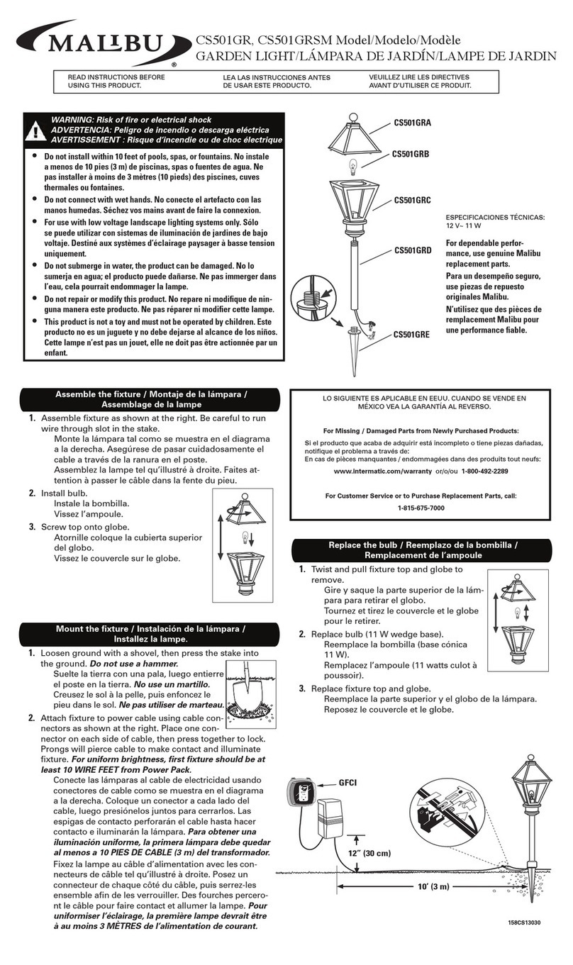
Cooper Lighting
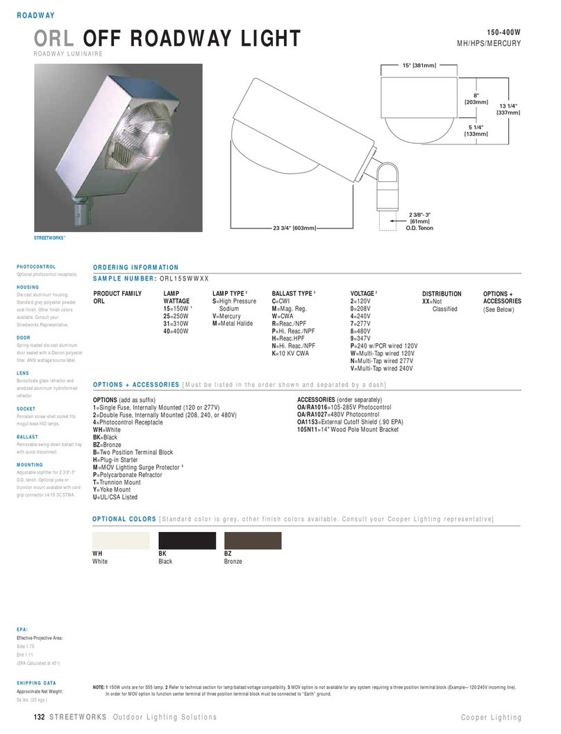
Cooper Lighting SURE-LITES CCX20RWH Specification sheet
Garden Lights
Garden Lights RUBUM+ manual

Malibu Boats
Malibu Boats LZ510 instructions

LIGMAN
LIGMAN LIGHTALK 14 LA-30035 installation manual
Schrack Technik
Schrack Technik LIVA Series Assembly instructions
Cooper Lighting
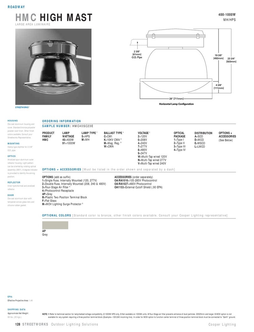
Cooper Lighting High Mast HMC40SC23E Specification sheet
