Eurofred ZSL3502 User manual
LIBRETTO ISTRUZIONI
PER L’USO E LA MANUTENZIONE
DEI CUOCIPASTA A GAS
OPERATION AND MAINTENANCE MANUAL
FOR
GAS PASTA COOKER
MANUEL D’INSTRUCTIONS
POUR L’UTILISATION ET L’ENTRETIEN
DES CUISEURS DE PATES A GAZ
BETRIEBS- UND WARTUNGSANLEITUNG
FÜR GAS-NUDELKOCHER
MANUAL DE INSTRUCCIONES PARA EL
USO Y EL MANTENIMIENTO DEL
APARATO DE GAS PARA COCER PASTA
REV. 01 / 2006
COD.: ZSL3502

Pag. 2
1. INSTALLAZIONE
1.1 AVVERTENZE IMPORTANTI
SOMMARIO
1.2 POSIZIONAMENTO
Leggere attentamente il presente libretto in quanto fornisce importanti indicazioni riguardanti la sicurezza d’in-
stallazione, d’uso e di manutenzione dell’apparecchio. Conservare con cura questo libretto per ogni ulteriore
consultazione dei vari operatori.
· L’installazione deve essere effettuata secondo le istruzioni del costruttore da personale professionalmente
qualificato.
· L’apparecchiatura deve essere utilizzata solo da personale addestrato all’uso della stessa.
· Disattivare l’apparecchiatura in caso di guasto o di cattivo funzionamento. Per l’eventuale riparazione rivolgersi
solamente ad un centro d’assistenza tecnica autorizzato dal costruttore ed esigere parti di ricambio origina-
li.
· Il mancato rispetto di quanto sopra può compromettere la sicurezza dell’apparecchiatura.
L’apparecchiatura è conforme alle seguenti normative:
- prescrizioni vigenti antinfortunistiche e antincendio;
- norme per l’installazione degli impianti a gas;
- norme igieniche.
Togliere l’apparecchio dall’imballo, verificarne
l’integrità e sistemarlo nel luogo d’utilizza-
zione.
Procedere alla messa in piano e alla regola-
zione in altezza agendo sui piedini livellatori
come indicato in (Fig. 1).
Se l’apparecchiatura viene posizionata con-
tro una parete, quest’ultima deve resistere a
valori di temperatura di 80°C e se è infiam-
mabile, è indispensabile l’applicazione di un
isolante termico.
Togliere dai pannelli esterni la pellicola pro-
tettiva staccandola lentamente per evitare
che restino tracce di collante.
Non ostruire le aperture o le fessure di
aspirazione o di smaltimento del calore
e posizionare l’apparecchio sotto una
cappa di aspirazione il cui impianto deve
essere a norma.
Fig. 1
1. INSTALLAZIONE.............................................................................................................................. Pag. 2
1.1 AVVERTENZE IMPORTANTI............................................................................................................................................... Pag. 2
1.2 POSIZIONAMENTO.............................................................................................................................................................. Pag. 2
1.3 SCARICO DEI FUMI (SOLO PER APPARECCHI CON P=> 14KW)................................................................................... Pag. 3
COLLEGAMENTO A CANNA FUMARIA A TIRAGGIO NATURALE ......................................................................................Pag. 3
COLLEGAMENTO SOTTO CAPPA ASPIRANTE..................................................................................................................Pag. 3
1.4 COLLEGAMENTO GAS........................................................................................................................................................ Pag. 4
PRESCRIZIONI PER L’INSTALLAZIONE .............................................................................................................................Pag. 4
CONTROLLI DA ESEGUIRE PRIMA DELL’INSTALLAZIONE ..............................................................................................Pag. 4
CONTROLLO DELLA POTENZA TERMICA .........................................................................................................................Pag. 5
CONTROLLO DELLA PRESSIONE DEL GAS......................................................................................................................Pag. 5
1.5 COLLEGAMENTO IDRICO................................................................................................................................................... Pag. 5
1.6 COLLEGAMENTO ALLO SCARICO..................................................................................................................................... Pag. 5
1.7 ALLACCIAMENTO A UN GAS DIVERSO ............................................................................................................................. Pag. 6
2. ISTRUZIONI D’USO.......................................................................................................................... Pag. 7
2.1 MESSA IN FUNZIONE.......................................................................................................................................................... Pag. 7
2.2 IMPOSTAZIONE ................................................................................................................................................................... Pag. 7
3. PULIZIA E MANUTENZIONE ........................................................................................................... Pag. 9
3.1 MANUTENZIONE ORDINARIA............................................................................................................................................. Pag. 9
3.2 MANUTENZIONE STRAORDINARIA................................................................................................................................... Pag. 9
3.3 ELEMENTI DI CONTROLLO E DI SICUREZZA................................................................................................................... Pag. 9
Pag. 3
Le apparecchiature devono essere messe in opera in locali adatti all’evacuazione dei prodotti della combustione,
nel rispetto delle norme per la loro installazione.
Esistono i seguenti tipi di collegamento:
1.3 SCARICO DEI FUMI (SOLO PER APPARECCHI CON P=> 14KW)
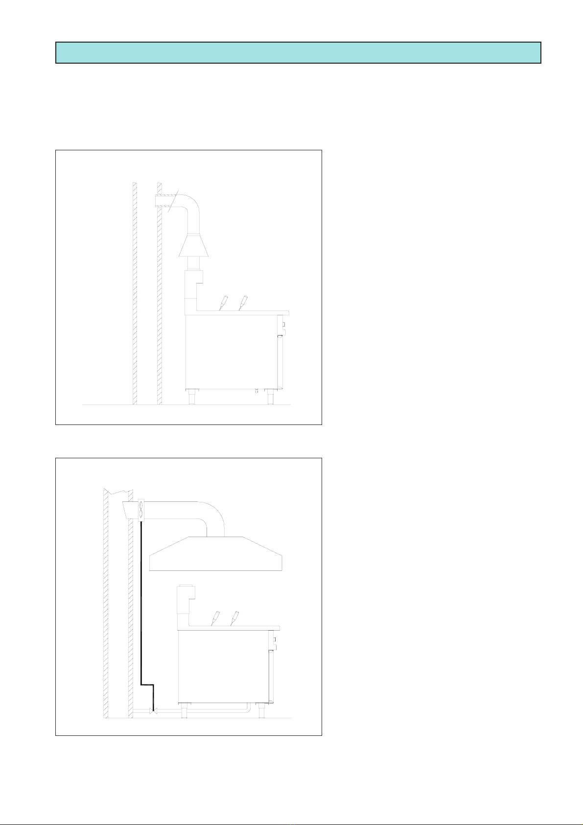
COLLEGAMENTO A CANNA FUMARIA A TIRAGGIO NATURALE
L’installazione degli apparecchi con scarico dei
gas combusti verso l’esterno tramite un camino
deve essere fatta come indicato in figura:
Il proseguimento avviene verso l’esterno o in un
camino mediante un’appropriata conduttura resi-
stente ad una temperatura di 300°C di diametro
uguale al fungo (Fig. 2).
ATTENZIONE: Tale intervento deve garantire che
l’evacuazione dei fumi non venga ostacolata da
ostruzioni e/o da eccessiva lunghezza del tubo
di scarico (lunghezza massima 3m).
COLLEGAMENTO SOTTO CAPPA ASPIRANTE
Quando l’apparecchio viene installato sotto
cappa aspirante, bisogna verificare che vengano
rispettate le seguenti indicazioni:
Il volume aspirato deve essere superiore a quello
dei gas combusti generati (vedere la normativa
in vigore).
L’alimentazione gas all’apparecchio, deve essere
controllata direttamente da tale sistema e deve
interrompersi qualora la portata scenda al di sotto
dei valori prescritti.
La riammissione del gas all’apparecchio deve
potersi fare solo manualmente.
La parte terminale del condotto di evacuazione
dell’apparecchiatura deve essere posta all’inter-
no della proiezione del perimetro di base della
cappa (Fig. 3).
Fig. 2
Fig. 3
Il camino antivento viene fornito su richiesta.
Pag. 4
40
150
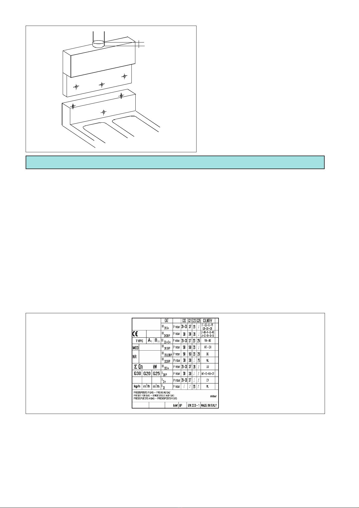
Per montare il camino procedere come segue
(Fig. 4):
- togliere la prolunga camino;
- infilare il camino sull’apparecchio come in-
dicato in figura;
- avvitare il camino all’apparecchio con le 3
viti per il fissaggio che vengono consegnate
con il camino.
1.4 COLLEGAMENTO GAS
PRESCRIZIONI PER L’INSTALLAZIONE
Le operazioni di installazione, gli eventuali adattamenti ad altri tipi di gas, la messa in funzione e l’eliminazione degli
inconvenienti negli impianti, devono essere eseguiti unicamente da personale qualificato, secondo i regolamenti
e le norme in vigore. Gli impianti del gas, i collegamenti elettrici e i locali di installazione degli apparecchi devono
essere conformi ai regolamenti ed alle norme vigenti. In particolare, occorre considerare che l’aria necessaria
per la combustione dei bruciatori è di 2m3/h per kW di potenza installata.
Devono essere rispettate le norme per la prevenzione degli infortuni e le normative di sicurezza antincendio
e anti-panico negli esercizi aperti al pubblico. Durante l’installazione sono da osservare e rispettare le norme
riportate di seguito:
Legge n 1083 del 06/12/71: norme per la sicurezza dell’impiego del gas combustibile.
Norme UNI-CIG7129/72 e UNI-CIG7131/72: norme per impianti a gas alimentati dalla rete di distribuzione o
gas GPL.
Circolare del ministero dell’interno n.68 del 25/11/1969 e sue varianti: norme di sicurezza per impianti termici a
gas di rete.
Lettera circolare n.412/4183 DEL 06/02/1975: norme di sicurezza per impianti cucine a gas di petrolio liquefatto
GPL.
Norme prevenzione infortuni.
Controllare sulla targhetta tecnica posta all’interno della porta, che l’apparecchio sia stato collaudato ed omologato
per il tipo di gas disponibile presso l’utente.
Verificare che gli ugelli montati sull’apparecchiatura, corrispondano al tipo di gas disponibile.
Controllare con i dati riportati sulla targhetta tecnica, che la portata del riduttore di pressione sia sufficiente per
l’alimentazione dell’apparecchiatura (Fig. 5).
L’apparecchio, salvo richieste diverse al momento dell’ordine, è regolato in fabbrica per il funzionamento con
gas G20 ad una pressione di 20mbar.
Evitare di interporre delle riduzioni di sezione tra il riduttore e l’apparecchio. Si consiglia di montare un filtro gas
a monte del regolatore di pressione al fine di garantire un funzionamento ottimale.
Fig. 4
Fig. 5
CONTROLLI DA ESEGUIRE PRIMA DELL’INSTALLAZIONE
Pag. 5
CONTROLLO DELLA POTENZA TERMICA
Durante la prima installazione ed in occasione di ogni intervento di manutenzione o adattamento ad un altro
tipo di gas, è necessario effettuare una misura di portata termica nominale. Questa misura si può fare usando
il metodo volumetrico, con l’ausilio di un conta litri e di un cronometro. Dopo aver controllato la pressione di
allacciamento e il diametro degli iniettori dei bruciatori, misurare la portata oraria del gas e confrontare il dato
acquisito con quello riportato nella tabella dati tecnici alla voce “consumo di gas”. E’ ammessa una tolleranza
del ±5% del valore nominale.
L’apparecchio dovrà essere alimentato con uno
dei gas le cui caratteristiche e la cui pressione
sono riportate nella tabella.
Collegare l’apparecchiatura ad un tubo spe-
ciale per gas di sezione interna non inferiore
ai 16mm di diametro per connessioni da G1/2”
e per connessioni da G3/4” di diametro non
inferiore ai 20mm. Il raccordo deve essere in
metallo e il tubo può essere fisso o flessibile. Fare attenzione che il tubo flessibile metallico di collegamento al
raccordo gas non tocchi parti surriscaldate e che non sia sottoposto a sforzi di torsione. Impiegare fascette di
fissaggio conformi alle norme d’installazione. Prevedere rubinetti o saracinesche aventi un diametro interno non
inferiore al tubo di raccordo sopraindicato. Dopo l’allacciamento alla rete del gas è necessario controllare che non
vi siano fughe nei giunti e nei raccordi. A questo scopo usare dell’acqua saponata o un prodotto schiumogeno
specifico per l’individuazione delle perdite.
NON USARE MAI FIAMMIFERI ACCESI.
TIPI DI GAS PRESSIONE IN mbar.
NOM. MIN MAX
GAS METANO G20 20 18 25
G.P.L. G30/31 28-30/37 25/25 35/45
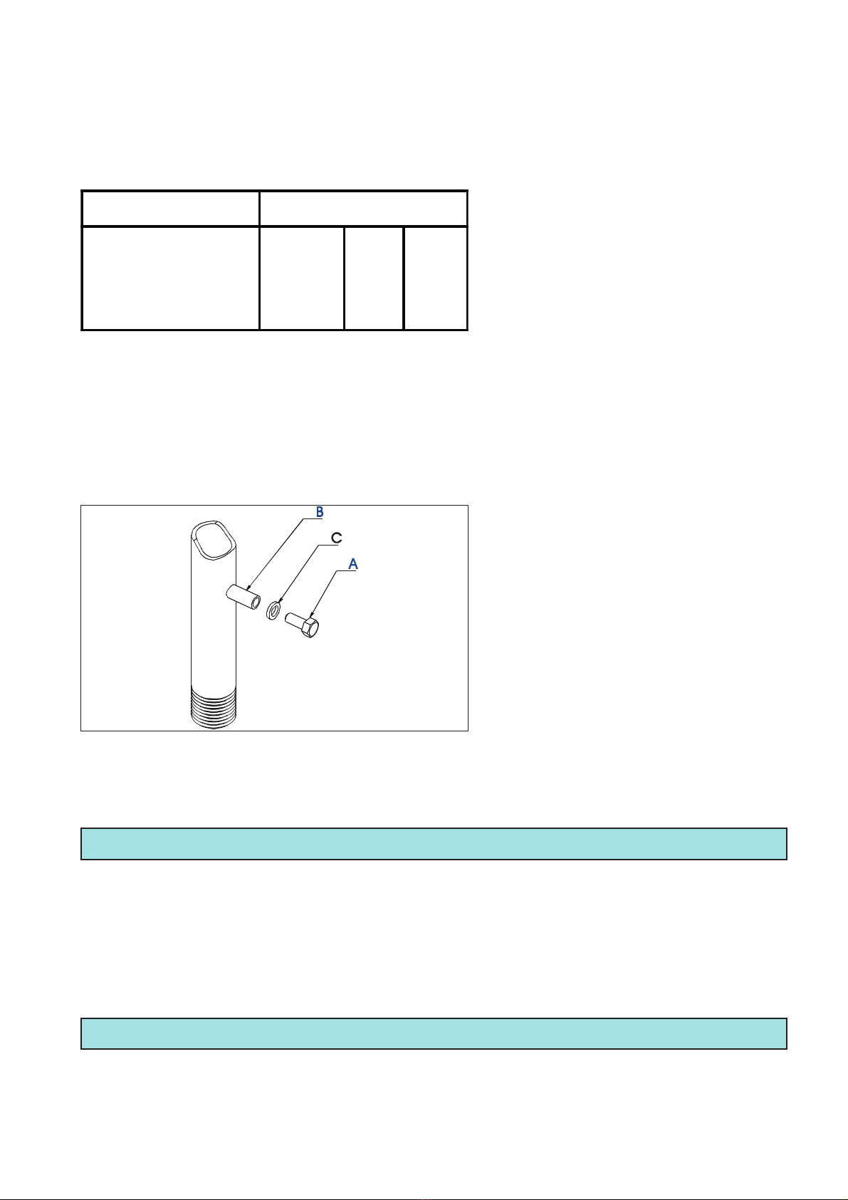
CONTROLLO DELLA PRESSIONE DEL GAS
La pressione del gas di alimentazione deve
essere misurata all’altezza della presa di pres-
sione (Rif. B) dopo aver tolto la vite di tenuta
(Rif. A). Per mezzo di un tubo flessibile, colle-
gare alla presa di pressione un misuratore (per
esempio un manometro a liquido, con risoluzio-
ne minima di 0,1mbar) e misurare la pressione
in entrata con l’apparecchio in funzione. Se il
valore della pressione non è compreso entro i
limiti inferiore e superiore indicati nella tabella,
non sarà possibile installare definitivamente
l’apparecchio.
Spegnere l’apparecchiatura, scollegare il manometro, richiudere la vite di tenuta senza dimenticare di inserire
la rondella (Rif. C) e contattare l’Ente erogatore del gas per una verifica della pressione di rete. A tal proposito
potrebbe essere necessario inserire un regolatore di pressione a monte dell’apparecchiatura.
Fig. 6
1.5 COLLEGAMENTO IDRICO
- La massima pressione dell’acqua ammessa è di 3bar (300kPa).
- Ai fini di una corretta installazione, l’apparecchio deve essere alimentato con acqua potabile.
- Il tubo di entrata dell’acqua deve essere allacciato alla rete idrica mediante un rubinetto d’intercettazione che
possa essere chiuso quando l’apparecchio non è in funzione o è in corso di manutenzione.
- Tra il rubinetto e il cuocipasta è necessario installare un filtro meccanico per impedire l’entrata di particelle
ferrose che, ossidandosi, alla lunga potrebbero intaccare la vasca.
- Prima di raccordare l’ultimo tratto di tubazione, si consiglia di far defluire dell’acqua al fine di togliere gli eventuali
residui ferrosi nel tubo.
1.6 COLLEGAMENTO ALLO SCARICO
Lo scarico dell’acqua deve confluire in un sifone aperto in modo da non permettere il contatto tra lo scarico dell’ap-
parecchio ed il sifone stesso, come prescritto dalle norme d’igiene in vigore. E’ necessario prevedere uno scarico
per l’apparecchio. La tubazione di scarico dovrà resistere alle alte temperature.
This manual suits for next models
4
Table of contents
Languages:


