Euroscreen Thor User manual
1
Thor
Made in Sweden
1
1
2
2
3
3
4
4
A A
B B
C C
D D
SHEET 1 OF 1
DRAWN
CHECKED
QA
MFG
APPROVED
Niclas 2013-09-23
DWG NO
TITLE
SIZE
C
SCALE
REV
160
160
51 54
20
27
27
7
03 okt 2014, 17:10

2
3
Thank you for choosing a Euroscreen®to be part of your AV
installation. We hope it will bring you many hours of entertainment and/or
education depending on your preference. Please read through the
manual completely before installation and usage.
Tack för att ni valt en Euroscreen® som en del i er AV-installation. Vi
hoppas den kan ge er många timmar av underhållning och/eller
utbildning, beroende på aktivitet. Läs igenom hela manualen innan
installation och användning.
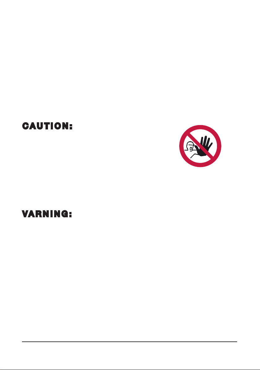
CAUTION: The installation must be wired
and connected by a certified electrician!
This screen is intended to be installed indoors, in a dry environment.
The current should at no point be put on both phases simultaneously.
Switching from ”up” to ”down” or vice versa should always go through
”stop”. Nor may the current stay live for more than 5 minutes
continously. Ignoring these instructions will ruin the internal limit switches!
Please note that most of the parts used to secure the bottom dowel during transport are parts also
needed to mount the screen. DO NOT THROW THEM AWAY!
VARNING: Installationen måste kopplas av behörig elektriker!
Denna produkt är avsedd att installeras inomhus i en torr miljö.
Matarströmmen får aldrig ligga på bägge faserna samtidigt. När faserna byts från ”upp” till ”ner” eller
tvärtom skall detta alltid ske via ”stopp”. Strömmen skall heller aldrig ligga på mer än 5 minuter. Om
inte dessa instruktioner följs riskerar man att motorns gränslägesbrytare förstörs!
Vänligen notera att de flesta delar som låser bottenprofilen under transport också används till att
montera upp duken. KASTA INTE DEM!
Electrical specifications / Elektriska specifikationer
Input / Matarspänning: 230V (AC)
Power / Effekt: 200W
4
1
1
2
2
3
3
4
4
5
5
6
6
A A
B B
C C
D D
Niclas 2013-09-23
Designed by Checked by Approved by Date
1 / 1
Edition Sheet
Date
45,97
6,35
15,88
101,60
38,10 38,10 12,70
11,10
5,16
3x
10,50
6,50
10,50
6,50
13,50
6,50
90
84
15
40
75
110
137
150
4
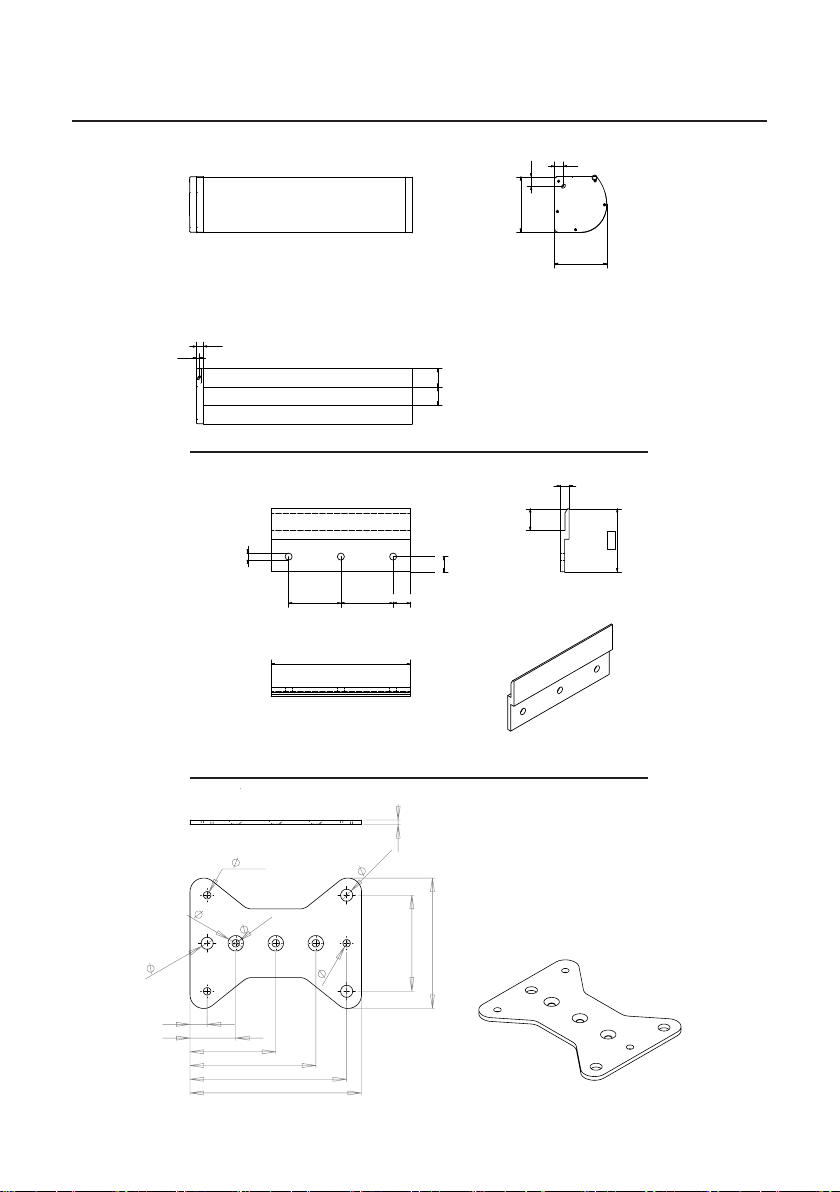
fig 2
fig 3
Wall bracket / Väggkonsol
Ceiling bracket / Takkonsol
1
1
2
2
3
3
4
4
A A
B B
C C
D D
SHEET 1 OF 1
DRAWN
CHECKED
QA
MFG
APPROVED
Niclas 2013-09-23
DWG NO
TITLE
SIZE
C
SCALE
REV
160
160
51 54
20
27
27
7
Overview / Översikt
1
1
2
2
3
3
4
4
A A
B B
C C
D D
SHEET
1
OF
1
DRAWN
CHECKED
QA
MFG
APPROVED
Niclas 2013-09-23
DWG NO
TITLE
SIZE
C
SCALE
REV
160
160
51 54
20
27
27
7
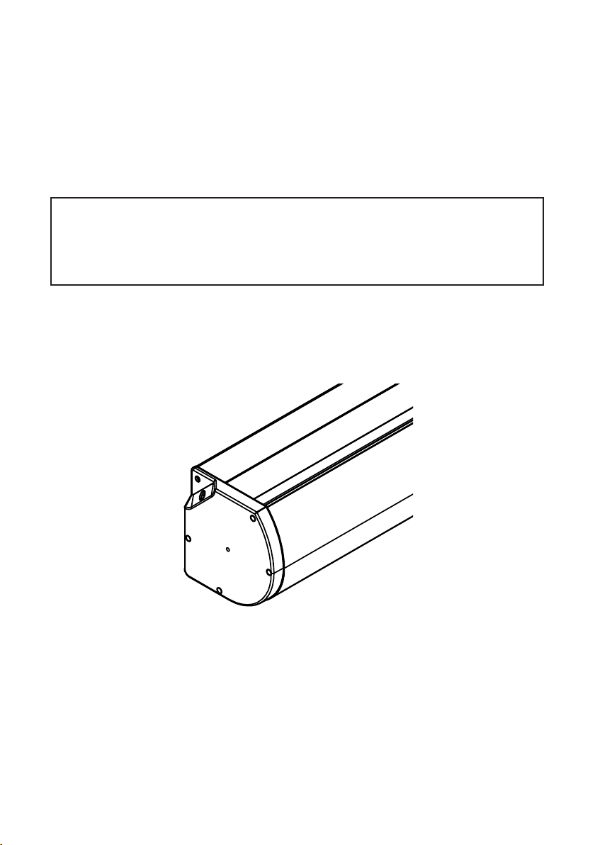
Case / Kassett
fig 1
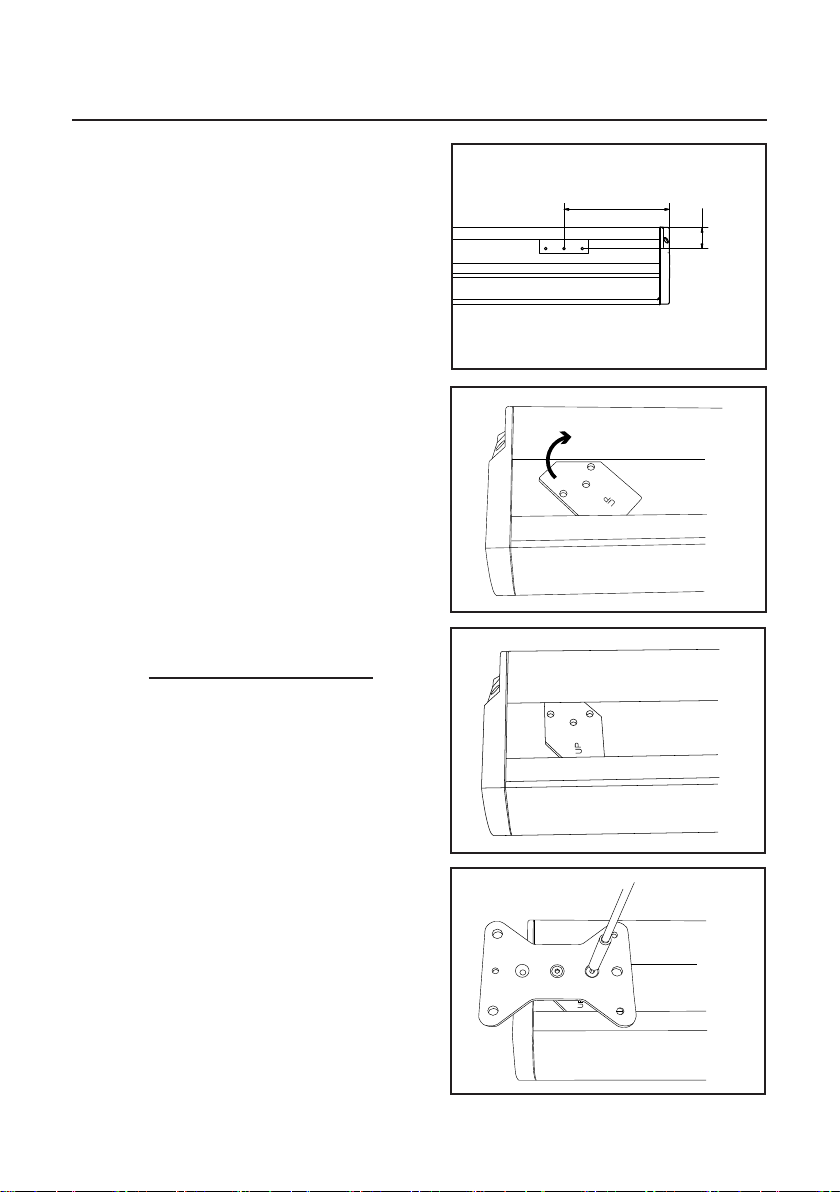
Unpacking / Uppackning
UK: Release the dowel from the bracket by
removing the screw.
Remove the bracket and its fastening plate
from the case.
The bracket and the plate inserted in the
track of the case is needed if the screen
should be mounted in the ceiling!
Remove the dowel holder from the bottom
dowel. Put the screw back into dowel.
SE: Lossa bottenprofilen från konsolen
genom att ta bort skruvförbandet (se fig.4).
Skruva av konsolen och ta ur fästplattan ur
kassettspåret (se fig.5).
Konsolen och fästplattan behövs om
filmduken skall monteras i tak!
Skruva bort bottenlisthållaren. Sätt tillbaka
skruven i bottenprofilen (se fig.6).
fig 4
fig 5
fig 6
6
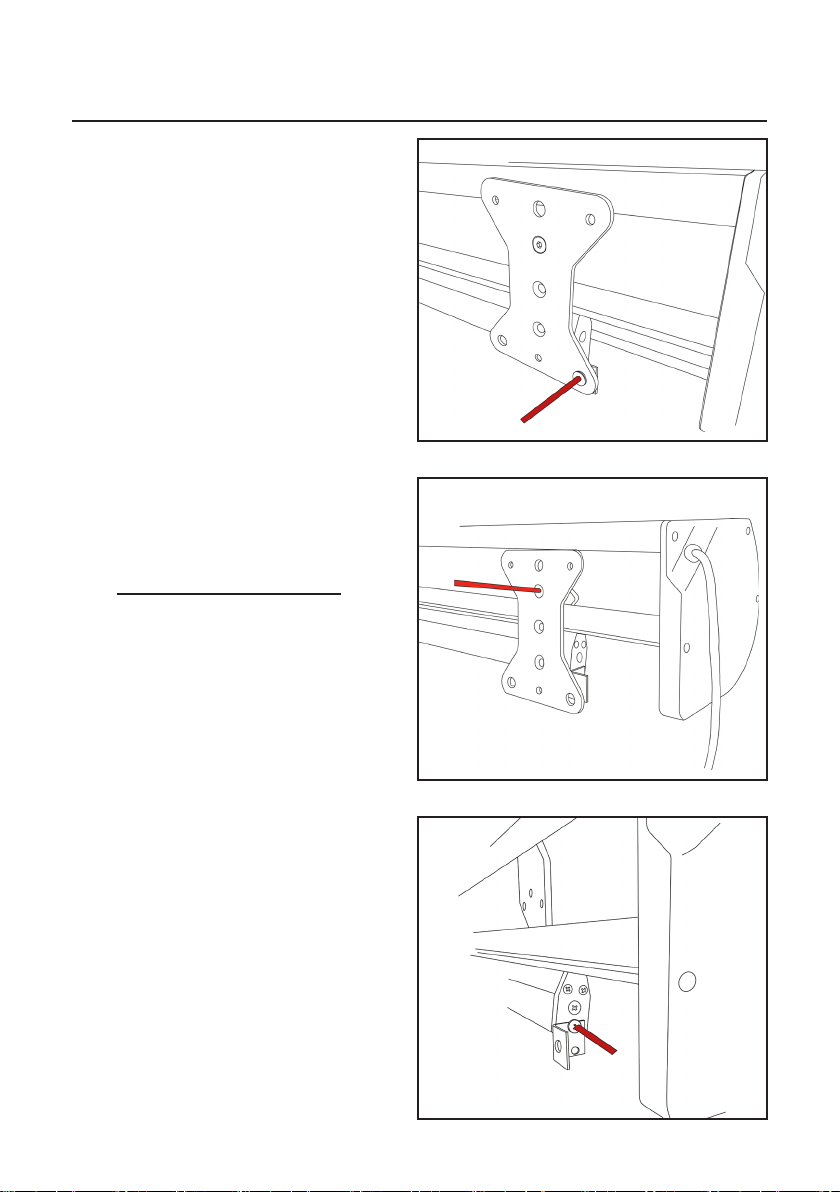
Assembly / Montering
UK: The ”Thor” screen can be mounted on the wall
or in the ceiling. Keep the screen horizontal at all
times during installation.
Wall mount:
1. Mount the wall brackets and make sure they are
levelled. Sideways spacing isn’t crucial as they can
slide sideways but recommended spacing is shown
in fig 7.
However - The brackets should never be mounted
more than 40cm in from the ends!
Please note that a distance of 20mm is
required above the case’ final position to allow the
mounting.
2. Mount the case. Make sure the case hooks
properly over the bracket.
Ceiling mount:
1. Mount the bracket inserts. Note ”UP”-mark
(fig 8 & 9).
2. Fasten the ceiling bracket using two screws for
each bracket and appropriate threadlocker (not
supplied) (fig 10). Please note that the ceiling bracket
is reversible and offers two different sets of holes of
your choise!
3. Attach to the ceiling using appropriate fasteners
(not supplied).
SE: ”Thor” kan monteras på vägg eller i tak.
Håll duken horisontell under hela installationen.
Väggmontering:
1. Skruva upp väggkonsolerna vågrätt. Exakt posi-
tionering i sidled är inte nödvändig då kassetten kan
glida på konsolerna. Rekommenderad positionering
visas i fig 7. Konsolerna får dock aldrig monteras
längre in än 40cm från kanterna!
Notera att ett spel på 20mm krävs över kassettens
slutliga position för att montering skall kunna ske.
2. Häng upp kassetten. Se till att kassetten hakar
ordentligt över konsolerna.
Takmontering:
1. För i konsolinläggen - notera ”UP”-markeringen
(fig 8 & 9).
2. Fäst takkonsolerna med två skruvar vardera och
använd lämplig gänglåsning (medföljer inte) (fig 10).
Observera att takkonsolen kan monteras på två olika
håll beroende på vilken hålbild som önskas.
3. Fäst upp i taket med lämpliga fästbeslag.
1
1
2
2
3
3
4
4
5
5
6
6
A A
B B
C C
D D
Niclas 2013-09-23
Designed by Checked by Approved by Date
1 / 1
Edition Sheet
Date
200
45
fig 7
fig 8
fig 9
fig 10
7
Limit setting / Gränslägen
UK: These pictures shows the screen with the motor moun-
ted to the left from the audience perspective (standard).
SE: Dessa bilder visar filmduken med motorn monterad på
vänster sida från åskådaren sett (standard).
SE:
Filmdukens gränslägen är ställda från fabrik. Ändring av gränslägena skall endast göras med
försiktighet DÅ DET KAN SKADA ELLER FÖRSTÖRA DUKEN!
1. Justering av det ÖVRE gränsläget visas i fig 11 (gul skruv).
- Vrid medurs för att sänka det övre gränsläget.
- Vrid moturs för att höja det övre gränsläget.
(Om motorn är monterad på höger sida är det istället vit skruv som skall användas.)
2. Justering av det NEDRE gränsläget visas i fig 12 (vit skruv).
- Vrid medurs för att höja det nedre gränsläget.
- Vrid moturs för att sänka det nedre gränsläget.
DET SKALL ALLTID FINNAS MINST ETT HELT VARV FILMDUKSMATERIAL KVAR PÅ RÖRET!
(Om motorn är monterad på höger sida är det istället gul skruv som skall användas.)
OBS: Den faktiska positionen av ett justerat läge kommer bara att visas efter att duken har
körts igen. Till exempel: Om det nedre läget har justerats måste duken köras upp 10-20cm
och sedan ner igen för att se var läget har hamnat.
Repetera tills önskat läge uppnåtts.
fig 11
UK:
The screens settings has been set at the factory.
Changes to these settings should be done with
caution AS THIS MAY CAUSE DAMAGE TO OR RUIN
THE SCREEN!
1. Adjustment to the UPPER limit is shown in fig 11
(yellow screw).
- Turn clockwise to lower the upper limit.
- Turn anticlockwise to raise the upper limit.
(if the motor is located to the right the white screw should be used
instead.)
2. Adjustment to the LOWER limit is shown in fig 12
(white screw).
- Turn clockwise to raise the lower limit.
- Turn anticlockwise to lower the lower limit.
THERE SHOULD ALWAYS BE AT LEAST ONE
FULL TURN OF SCREEN MATERIAL LEFT ON THE
ROLLER!
(if the motor is located to the right the yellow screw should be used
instead.)
NOTE: The actual position of an adjusted limit will
only be shown accurately when the screen has
been run again.
For example - If the lower limit has been adjusted
you must run the screen up 10-20cm and then run
down again to see where the limit has been set.
Repeat until the desired limit has been achived.
fig 12
8
EN: To keep the surface flat you may need to adjust the
tensioning as the surface will change with time and
temperature. This is done with the tensioning screw
marked in fig 13. It is adjustable with 1/6 turn increments.
Only adjust it in a single increment at a time!
1. Carefully lift the bottom bar with a firm grip
2. Press the screw in 2-3mm to unlock it and turn it
clockwise to increase the tension, anti-clockwise to
decrease it
3. Let the screw come out and lock again
4. Leave the screen to hang and set for a minute
5. Repeat procedure if necessary
SE: För att bibehålla ytan slät kan trådarnas spänning behöva justeras emellanåt. Detta beror på att
dukmatrialet ändras med tid och temperatur. Justeringen görs med skruven som markerats i fig 13.
Tråden kan justeras i
1/6-dels varv per steg. Justera endast med 1 steg åt gången!
1. Lyft försiktigt bottenprofilen med ett stadigt grepp
2. Tryck in skruven 2-3mm för att släppa låset och vrid skruven medsols för att spänna tråden, mot-
sols för att släppa efter
3. Släpp ut skruven så att den hakar i sitt lås igen
4. Låt duken hänga och ”sätta sig” några minuter
5. Repetera om nödvändigt
Tensioning (TabTension only) / Trådspänning (endast TabTension)
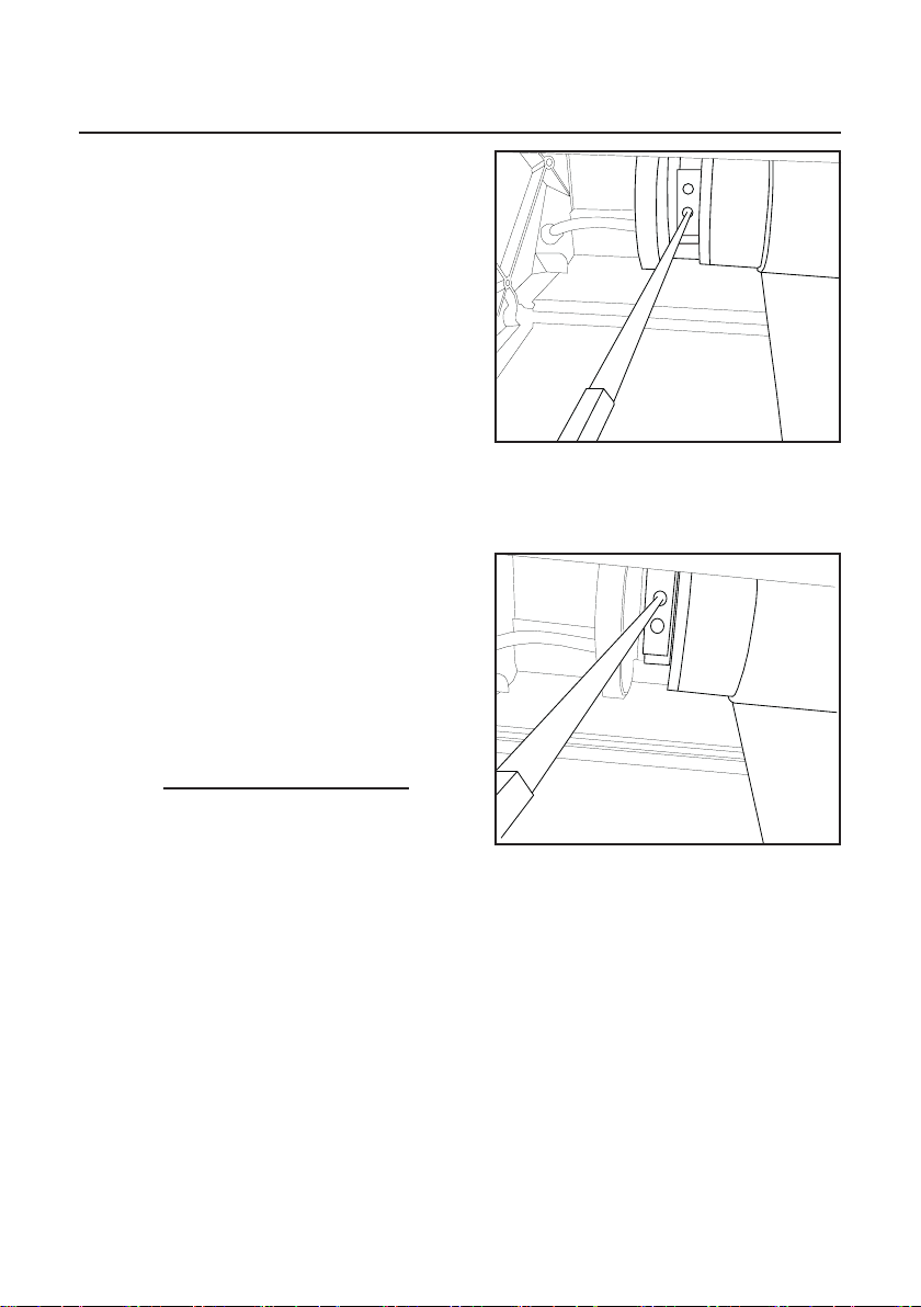
How to open case / Öppna kassetten
EN: The front lid can be
removed while the screen
remains installed on the wall.
To open the case remove the
screws shown in fig 14 & 15
on both ends. Lift and remove
the lid (fig 16).
SE: Täcklocket kan tas bort medan duken fortfarande
är installerad på väggen. Lossa skruvarna som visas i
fig 14 & 15 på båda sidor. Lyft och ta haka loss locket
(fig 16).
fig 14 fig 15
fig 16
fig 13
9
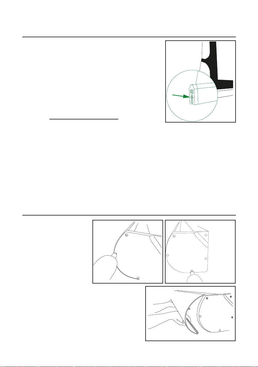
Height adjustment / Höjdjustering
fig 17
fig 18
UK:
Some of the Thor screens (width dependable) has
a built in height adjustment in case the ceiling for
instance, doesn’t allow the installation to be level.
There is approx. 5mm adjusting room up and 5mm
down on each side of the screen. We recommend
you to primarily adjust on the idler/spear side.
To lower the screen turn the adjustment screw
clockwise (see fig 17 & 18).
To raise the screen turn it anticlockwise.
SE:
Somliga modeller av filmduken Thor har inbyggd
höjdjustering för de tillfällen en vågrät installation inte
medges; ett snett tak tex. Där är ungefär 5mm juster-
mån upp och ner på var sida. Vi rekommenderar att
man i första hand justerar på tappsidan.
Vrid justerskruven (se fig 17 & 18) medurs för att
sänka duken.
Vrid moturs för att höja duken.
Maximum continous running time: 5 min
Forward/Reverse delay: 0,5 s
Fuse: T5L250V
Input: 230 VAC / 50 Hz
Max load: 4 A
Radio signal frequency: 433,92 MHz
Cable specifications:
Thickness: Ø 7 mm
Cable dimensions:
Motor to box: 4 x 0,75 mm²
Case to wall plug: 3 x 0,75 mm²
L: 2800 mm
Wires: Black - Up
Brown - Down
Blue - Neutral
Green/Yellow - Ground
Maximal kontinuerlig drift: 5 min
Fördröjning framåt/bakåt: 0,5 s
Säkring: T5L250V
Matarspänning: 230 VAC / 50 Hz
Max Strömbelastning: 4 A
Radiofrekvens: 433,92 MHz
Kabelspecifikationer:
Tjocklek: Ø 7 mm
Kabel dimensioner:
Motor till box: 4 x 0,75 mm²
Kassett till väggkontakt: 3 x 0,75 mm²,
L: 2800 mm
Ledare: Svart - Upp
Brun - Ner
Blå - Neutral
Gul/Grön - Jord
Control Box / Styrboxen

10
1
1
2
2
3
3
4
4
5
5
6
6
A A
B B
C C
D D
210730
Niclas 2012-06-18
Designed by Checked by Approved by Date
1 / 1
Edition Sheet
Date
126
37
82
[mm]
fig 19
fig 20
Down / Ner
Stop / Stopp
Up / Upp
Case locking screws / Låsskruvar
Fuse / Säkring
Pull resistance / Dragavlastning
Contact closure / RS232 / RS485 (6-pin RJ11)
Supply terminal / Matarström
Motor terminal / Inkoppling motor
12V Trigger (2,5mm)
IR Extender (3,5mm)
INTERIOR OVERVIEW / INTERIÖR ÖVERSIKT
EXTERIOR OVERVIEW / EXTERIÖR ÖVERSIKT

11
Basic Installation / Grundinstallation
RADIO MOUNTING RECOMMENDATIONS
For safest radio functionality please:
a. Do not install the receiver against or
sheltered by a metallic part as this might affect
the radio transmission.
b. Minimum distance above floor: 150cm
c. Minimum distance below ceiling: 30cm
d. Minimum distance between receiver and
transmitter: 30cm
e. Minimum distance between two receivers:
20cm
RF PROGRAMMING MODE:
To be able to connect the different RF
transmitters to the Control Box it is nedessary
to put the Control Box in programing mode.
This can be done in three different ways:
a. Press and hold the STOP button on the box
(approx 6s)
b. Press and hold STOP button on an
ALREADY PROGRAMMED transmitter (approx
6s)
c. Disconnect the Control Box. Press and hold
UP button on an UNPROGRAMMED
transmitter. It shall blink twice and the third time
it shines continously. During the continous light
the Control Box is reconnected to power.
Programming mode is confirmed with slow red
flashes and lasts for 5s and then exits back to
normal.
DELETING ALL RF TRANSMITTERS:
To be able to erase all programmed RF tranmit-
ters (remotes and AutoLinks) from the Control
Box memory you need to have the #210727
hand held remote.
a. set the Control Box in programming mode
(see above).
b. Press and hold the small button through the
hole on the backside of #210727, using a nar-
row object (pencil, paperclip etc.) in approx 2s.
c. The deletion is confirmed by the Control Box
by three quick flashes.
REKOMMENDATIONER FÖR RADIO
För bästa radiofunktion bör följande följas:
a. Installera inte mottagaren bakom eller intill
metalldelar då det kan störa
radiokommunikationen.
b. Lägsta höjd över golvet: 150cm
c. Minsta avstånd nedanför taket: 30cm
d. Minsta avstånd mellan sändare och
mottagare: 30cm
e. Minsta avstånd mellan två mottagare: 20cm
RF PROGRAMMERINGSLÄGE:
För att kunna ansluta de olika RF sändarna till
Control Boxen måste den sättas i
programmeringsläge. Det kan göras på tre
olika sätt:
a. Håll Control Boxens STOP-knapp intryckt
(ca 6s)
b. Håll inne STOP-knappen på en REDAN
INPROGRAMMERAD sändare (ca 6s)
c. Gör Control Boxen strömlös. Håll
UPP-knappen på en OPROGRAMMERAD
sändare intryckt tills den blinkat 2ggr och
övergått till ett fast sken. Medan sändaren lyser
ansluts strömmen till Control Boxen igen.
Programmeringsläget bekräftas av ett långsamt
rött blinkande, varar i 5s sedan går det tillbaka
till normalläge.
RADERA ALLA SÄNDARE UR MINNET:
För att kunna radera alla sändare krävs hands-
ändare #210727.
a. Försätt Control Boxen i programmeringsläge
(se ovan).
b. Tryck och håll inne den lilla knappen i hålet
på handkontrollens baksida med ett smalt
föremål (penna/gem etc.) i ca 2s.
c. Raderingen bekräftas av Control Boxen med
tre snabba blinkningar.

12
Code
Set
fig 21
fig 24
fig 25
fig 22
fig 23
Control options / Alternativa styrningar
IR REMOTE
RF REMOTE
IR FJÄRRKONTROLL
RF FJÄRRKONTROLL
To control the box with RF-remote,
add Euroscreen®s remote #210727
(fig 22) or wall switch #210724
(fig 23). Program as follows:
a. Put the Control Box in Program-
ming Mode (see page 4)
b. Within 5s - Press UP on the
remote you wish to add. The Con-
trol Box confirms with three quick
flashes
c. Done!
d. To delete transmitter from memory perform
the same procedure as above but press DOWN
on the remote you wish to exclude in step ”b”.
För att styra boxen med RF-fjärrkontroll, kom-
plettera med Euroscreen®s sändare #210727
(fig 22) eller väggsändare #210724 (fig 23).
Programmera enligt följande:
a. Sätt Control Boxen i programmeringsläge (se
sid 4)
b. Tryck UPP-knappen på den sändare du
vill lägga till inom 5s. Con-
trol Boxen bekräftar med tre
snabba blinkningar
c. Klart!
d. För att radera en sändare
från minnet utför samma som
ovan men tryck NED i steg ”b”.
AUTOLINK AUTOLINK
To control the box with AutoLink, add
Euroscreen®210722-2(A) (fig 24) to the
projector. Install as follows:
a. Set the Control Box in
programming mode (see page 9)
b. Within 5s - Press ”Code” button
on the backside of the AutoLink
(see fig 25). The Control Box
confirms with three quick flashes
c. Press ”Set” on the trigger for 3s
until trigger sounds (buzz) and
För att styra Control Boxen med Au-
toLink, komplettera projektorn med
Euroscreen®210722-2(A) (fig 24).
Programmera enligt följande:
a. Försätt Control Boxen i
programmeringsläge (se sid 9)
b. Tryck inom 5s en gång på
”Code”-knappen på AutoLinkens
baksida (se fig 25). Control Boxen
bekräftar med tre snabba
blinkningar
To control the box with IR-remote, add
Euroscreen®s remote #210704 (fig 21).
För att styra boxen med IR-fjärr, kom-
plettera med Euroscreen®s fjärrkontroll
#210704 (fig 21).
flashes once. Turn on the
projector within 10s from the
”flash and buzz”.
d1. The led of the trigger flas-
hes and the buzzer sounds 3
times = settings succeeded.
d2. The led of the trigger flash
and the buzzer sound 1 time =
settings failed.
c. Tryck in ”Set” på trigger i
3s tills den piper och blinkar 1
gång. Starta projektorn inom
10s från triggerns signaler.
d1. Triggern blinkar och piper
3ggr = installationen lyckades
d2. ”Triggern blinkar och piper
1gg = Installationen
misslyckades

13
1 2 3 4 5 6
fig 26
fig 27
12V TRIGGER 12V TRIGGER
RS232 /485 RS232 / 485
The Control Box can be controlled by RS232
signals. It is a ”mute” system so it can receive
the commands but not send confirmations
back.
The RS232 uses the RJ11 socket, pins 1 & 6,
see fig 26 below.
Control Boxen kan styras via RS232
signaler. Boxen är dock ”stum” - den kan ta
emot kommandon men kan inte skicka tillbaka
några bekräftesesignaler.
RS232 signalen använder sig av RJ11 kontak-
tens pinnar 1 & 6, se fig 26 nedan.
Pin positions
RJ11 Pin specifications:
1: 485A / 232GND
2: Dry contact DOWN
3: Dry contact STOP
4: Dry contact UP
5: Dry contact NEUTRAL
6: 485B / 232RX
DRY CONTACT CONTACT CLOSURE
The Controll Box can be controlled with dry
contact through the RJ11 socket (see fig 26
above). Make a connection between NEUTRAL
(pin 5) and one of pins 2 - 4 depending on
desired action.
Ex.: Connection between pins 2 & 5 will run
screen down.
Control Boxen kan styras med Contact closure
genom RJ11-portens pinnar 2 till 5 (se fig 26
ovan). Gör en slutning mellan NEUTRAL (pin 5)
och en av pinnarna 2 - 4 beroende på önskad
handling.
T.ex.: Slutning mellan pin 2 & 5 kommer att
köra ner duken.
IR EXTENDER EYE EXTERNT IR ÖGA
The Controll Box can be equipped
with an extended IR-eye in case
you wish to hide away the Control
Box. Available from Euroscreen®is
#210734 (fig 27), a 95cm extension.
Connects to the 3,5mm socket on
the Control Box.
Control Boxen kan utrustas med
externt IR-öga för de tillfällen ni
vill gömma undan Control Boxen.
I Euroscreen®s sortiment finns
#210734 (fig 27), en 95cm förläng-
ning som ansluts med 3,5mm
audiokontakt.
To control the box with a ”Projector 12V trigger”
signal add proper cable. The Control Box is
connected with a 2,5mm Audio plug. Available
from the Euroscreen range is the ”2,5 Audio/
open end” #210733. The Control Box can work
with currents ranging from 5V to 35V. Simply
connect and run.
För att styra duken med en projektors ”12V
trigger signal” behöver ni komplettera med
passande kablage. Contol Boxen kopplas in
med en 2,5mm Audiokontakt. Euroscreen®
erbjuder en ”2,5 Audio/öppna trådar-kabel”
(#210733). Control Boxen kan köras med
strömmar från 5V upp till 35V. Bara att ansluta
och köra.

14
15
REACH
The new EU chemicals legislation
Conformity of regulations
Draper Europe AB manufactures AV equipment within the brand Euroscreen®. These products are
controlled and certified by the below listed regulations.
REACH
Registration, evaluation, authorisation and limitation of chemicals. Regulation (EC) No 1907/2006 of the
European Parliament and of the European Council concerning the Registration, Evaluation, Authorisation and
Restriction of Chemicals (REACH).
All screen surfaces of Euroscreen®projection screens are approved by the REACH regulation.
ECHA
European Chemicals Agency (ECHA) gathers information on the properties of manufacturers and importers
chemical substances, which will allow their safe handling, and to register the information in a central
database.
Euroscreen®projection screens are printed with colours containing the following components:
CAS 1333-86-4, CAS 112-36-7, CAS 96-48-0, CAS 143-24-8, CAS 1559-34-8, CAS 2687-91-4,
CAS 111-90-0, CAS 34590-94-8 and CAS 126-86-3. These are all approved by ECHA.
RoHS
Restriction of Hazardous Substances Directive (RoHS) directive restricts the use of six hazardous materials in
the manufacture of various types of electronic and electrical equipment.
All electrical devises used in Euroscreen®products are RoHS certified.
WEEE
The Waste Electrical and Electronic Equipment Directive (WEEE Directive) is the European Community
directive 2002/96/EC on waste electrical and electronic equipment (WEEE) which, together with the RoHS
Directive 2002/95/EC, setting collection, recycling and recovery targets for all types of electrical goods.
Applicable Euroscreen®products are labeled with the WEEE symbol.
FR2000
FR2000 is an integrated management system for quality, environment, competence enhancement, health
and safety. This systems is derived from; ISO 9001, ISO 14001,SS 62 40 70, the Swedish work environment
authority regarding systematic environmental progress, and the Swedish rescue services agency regarding
systematic fire safety, SRVFS 2004:3.
Draper Europe AB is certified by FR2000 since 2010.
FTI
Producers responsibilty for recycling of packaging material is regulated by SFS 2006:1273. The recycling
process of packaging material is handled for its members by a central organization called FTI.
Draper Europe AB is a member of FTI.
Declaration of Conformity
Draper Europe confirms that Euroscreen®Electric meets Low Voltage Directive 2006/95/EG &
EMC Directive 2004/108/EC. This is a EN61140 Class I product with internal separation instead of protective
conductor (EN61140 7.2.2 Note 2).
Euroscreens® are CE-approved.
PATENT PENDING

16
Draper Europe AB / Västervallvägen 6 / 302 50 Halmstad
Tel: 035-14 42 90 / Fax: 035-14 42 91
Other manuals for Thor
1
Popular Indoor Furnishing manuals by other brands

Regency
Regency LWMS3015 Assembly instructions

Furniture of America
Furniture of America CM7751C Assembly instructions

Safavieh Furniture
Safavieh Furniture Estella CNS5731 manual

PLACES OF STYLE
PLACES OF STYLE Ovalfuss Assembly instruction

Trasman
Trasman 1138 Bo1 Assembly manual

Costway
Costway JV10856 manual


