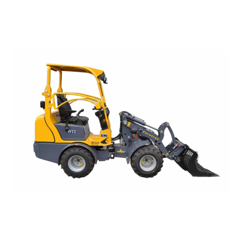
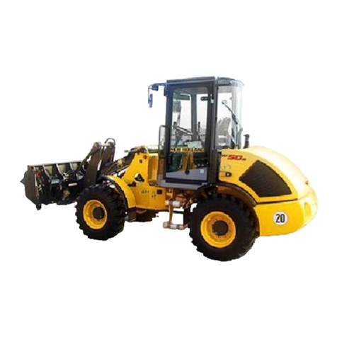
Eurotrac W11 User manual

Eurotrac Construc�on Machinery
Stougjesdijk 153
3271 KB Mijnsheerenland
The Netherlands
Tel: +31 (0) 18 66 12 333
E-mail: info@eurotrac.nl
WHEEL LOADER
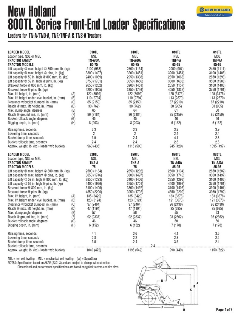
W11/W12S/W12F/W13F/T13F
OPERATION MANUAL
Eurotrac Construc�on Machinery
Stougjesdijk 153
3271 KB Mijnsheerenland
The Netherlands
Tel: +31 (0) 18 66 12 333
E-mail: info@eurotrac.nl
WHEEL LOADER
W11/W12S/W12F/W13F/T13F
OPERATION MANUAL

CONTENTS
W11 - W12S -W12F - W13F - T13F | Operation manual
1. GENERAL WARRANTY CONDITIONS ............................................................................................ 4
2. GENERAL .................................................................................................................................... 6
3. INFORMATION AND OPERATION ................................................................................................ 8
3.1 Standard configuration......................................................................................................................... 8
3.2 Operator responsibilities...................................................................................................................... 8
3.3 Mechanical responsibilities .................................................................................................................. 9
4. GENERAL INFORMATION & OPERATING INSTRUCTIONS ........................................................... 12
4.1 Main components .............................................................................................................................. 12
4.1.1 Engine and pump ................................................................................................................ 12
4.1.2 Motor and drive axle ........................................................................................................... 12
4.1.3 Braking system .................................................................................................................... 12
4.1.4 Wheels and tires ................................................................................................................. 12
4.1.5 Fuel cell ............................................................................................................................... 12
4.1.6 Electrical system ................................................................................................................. 12
4.1.7 Quick removal device .......................................................................................................... 13
4.1.8 Seat ..................................................................................................................................... 13
4.1.9 Multi-functional control handle ..........................................................................................15
4.1.10 Cab ...................................................................................................................................... 15
4.1.11 Pedals .................................................................................................................................. 19
4.1.12 Attachments ........................................................................................................................ 19
4.1.13 Instrument panel ................................................................................................................. 22
4.2 Operating procedure.......................................................................................................................... 29
4.3 Specifications and performance......................................................................................................... 42
4.4 Shipping procedure ............................................................................................................................ 48
4.5 Trailer procedure................................................................................................................................ 49
4.6 Storage procedure.............................................................................................................................. 50
4.7 Noise levels......................................................................................................................................... 50
5. MAINTENANCE SECTION ........................................................................................................... 51
5.1 General cleaning instructions............................................................................................................. 51
5.1.1 First maintenance program ................................................................................................. 52
5.2 Service ................................................................................................................................................ 52
5.2.1 Preparation for use ............................................................................................................. 52
5.2.2 Regular maintenance form .................................................................................................53
5.2.3 Liquid & lubricants .............................................................................................................. 67
6. TROUBLESHOOTING ................................................................................................................. 68
ANNEX 1: Hydraulic diagrams ......................................................................................................................... 72
Hydraulic diagram W11...................................................................................................................... 72
Hydraulic diagram W12S .................................................................................................................... 73
Hydraulic diagram W12F/W13F ......................................................................................................... 74
Hydraulic diagram T13F...................................................................................................................... 75
ANNEX 2: Electric diagrams ............................................................................................................................ 76
Electric diagram W11/W12S .............................................................................................................. 76
Electric diagram W12F/W13F/T13F ................................................................................................... 77
ANNEX 3: The label location chart of machine ............................................................................................... 80
ANNEX 4: Daily equipment inspection ............................................................................................................ 81

Page 3/81
April 2021W11 - W12S -W12F - W13F - T13F | Operation manual
EC DECLARATION OF CONFORMITY
MANUFACTURER
Name: Eurotrac Construction Machinery (Europe)
Address: Stougjesdijk 153, 3271KB Mijnsheerenland, Holland
HEREBY DECLARES THAT THE PRODUCT DESCRIBED BELOW:
Model W10 W11 W12-S W12-F W13-F T13-F
Serial number
Engine model D902 D1105 V1505 D1803 4TNV86CT 4TNV86CT
Engine power and
emission 16.1Kw
Euro-5 18.5Kw
Euro-5 18.4Kw
Euro-5 27Kw
Euro-5 35.5Kw
Euro-5 35.5Kw
Euro-5
Manufacturing year
2006/42/EC Machinery Directive
2014/30/EU (Electromagnetic compatibility)
(EU)2016/1628 Engine Pollutant Emission Directive
2000/14/EC & 2005/88/EC NOISE DIRECTIVE
Equipment according to the definition given by: Annex I, item 37 of Noise Directive
Conformity assessment procedure followed: Annex VI of Noise Directive
Notified body : European Certifying Organization S.p.A.,
No.0714, Via Mengolina 33,
Faenza(RA), Italy.
Measured sound power level: 98 dB Lwa Guaranteed sound power level: 101dB Lwa
Holder of the technical documentation: Manufacturer
COMPLIES WITH THE PROVISIONS OF THE FOLLOWING HARMONIZED STANDARDS:
EN 474-1:2006+A1:2009 Earth-moving machinery — Safety — Part 1: General requirements
EN 474-3:2006+A1:2009 Earth-moving machinery — Safety — Part 3: Requirements for loaders
THE TECHNICAL DOCUMENTATION WAS COMPILED BY THE EUROPEAN BODY:
Name : P.de Heus en Zonen Greup BV
Address : P.O. box 1529 – 3260BA Oud Beijerland, Holland
PERSON RESPONSIBLE FOR MAKING THIS DECLARATION:
Name: Title:
B. de Heus Quality and Production Manager
Mijnsheerenland (NL)
_____________ __________ __________________
Done at (place) On (date) Signature and stamp

Page 4/81
April 2021W11 - W12S -W12F - W13F - T13F | Operation manual
1. GENERAL WARRANTY CONDITIONS
This document presents the warranty conditions offered to any customer for all the pieces of equipments
manufactured in the Eurotrac Construction Equipment facilities and sold to him through the authorized Sales and
Service network.
The general warranty conditions hereunder described do govern the relationship between final customer of a
Eurotrac Construction Equipment product, hereunder called “the buyer” and Eurotrac Construction Equipment
factory, called “the manufacturer“.
The fact that the buyer places an order of a Eurotrac Construction Equipment product means that he has read the
present policy and does accept its provision. Any other general or particular provision, that differs from or
contradicts one of the general or particular conditions described hereafter which may appear in any document from
the buyer and especially in its general purchasing conditions, cannot be used against the manufacturer unless
accepted by Eurotrac Construction Equipment in a written agreement.
ARTICLE 1
Eurotrac Construction Equipment warrants that each new item of equipment is of good workmanship and is free
from mechanical defects provided that:
1. The product is installed and operated in accordance with printed Eurotrac Construction Equipment
Equipment’s instructions;
2. The product is used under normal operating conditions, for which it is designed;
3. The product is not subject to misuse, negligence or accident;
4. The product receives proper care, lubrication, protection and maintenance under the supervision of trained
personnel;
5. The product is normally protected from exterior aggressions whatever their origin.
ARTICLE 2
This warranty expires, unless otherwise agreed by Eurotrac Construction Equipment in a special provision,
15 months after shipment by the manufacturer, or 12 months after being placed in service, or after 1000 operating
hours.
ARTICLE 3
The Eurotrac Construction Equipment warranty is strictly limited to the replacement of defective parts and if the
repair does justify it, to the assistance of a technician. Parts shipping expenses, traveling and housing expenses of
personnel are to be paid by customer.
ARTICLE 4
The Eurotrac Construction Equipment warranty does not apply to fluids, oils, fuses, bulbs, accumulators, paint,
seals, tires, bumpers, pads and other consumables or normally wearing type items unless found to be defective prior
to use.
ARTICLE 5
All warranty claims from the Buyer must be sent by written to Seller who will be in charge of dealing with the
Manufacturer to address the problem in a timely manner.

Page 5/81
April 2021W11 - W12S -W12F - W13F - T13F | Operation manual
ARTICLE 6
All the expenses related to a warranty claim will be invoiced to the buyer until Eurotrac Construction Equipment
employees have evaluated the claim. Whatever the circumstances, the buyer should not refuse or delay the
payment. If the evaluation concludes to Eurotrac Construction Equipment’s full responsibility, a credit memo will be
issued in favor of the buyer.
The reseller (the location where the loader was bought), cannot accept a warranty claim of the defective parts by
the buyer, unless the buyer has issued a formal letter AND returned the parts.
ARTICLE 7
This warranty is extended by Eurotrac Construction Equipment only to the buyer of new products from Eurotrac
Construction Equipment or of its authorized distributors. The products purchased under this warranty are intended
for use exclusively by the buyer and his employees and by no other person. Therefore, there shall be no third party
beneficiary of this warranty.
ARTICLE 8
This warranty applies only to the original problem. In other words, if the product is used after the original problem
has been detected, the consequences thereof are not covered by this warranty.
ARTICLE 9
Under no circumstances whatever shall Eurotrac Construction Equipment and the seller be liable for any special or
consequential damages, whether based on lost goodwill, lost resale profits, work stoppage, impairment of other
goods or otherwise, and whether arising out of breach of any express or implied warranty, breach of contract,
negligence or otherwise, except only in the case of personal injury as may be required by applicable law.
ARTICLE 10
The warranty is automatically void in the following cases:
1. The product has received some modification, not advised by Eurotrac Construction Equipment or not done
following Eurotrac Construction Equipment requirements.
2. Some original parts have been replaced by parts not provided by Eurotrac Construction Equipment.
ARTICLE 11
This warranty and all undertaking of Eurotrac Construction Equipment shall be governed by the laws of
manufacturer’s country and discussed in front of nearest court from the manufacturer’s facility even in case of
multiple of defenders.

Page 6/81
April 2021W11 - W12S -W12F - W13F - T13F | Operation manual
2. GENERAL
This instruction manual is intended for all users of the machine: the company manager, the department head, the
driver, as well as the whole personnel that works with or near to the equipment.
GENERAL WARNING
1. Before using the machine, go through this manual and comply with all its instructions.
2. Also carefully read the instructions that appear on the plates fixed onto the machine and keep them readable.
3. Keep this instruction manual at the disposal of all operators.
4. Make sure that any person to whom you entrust the machine is qualified to fulfill the safety requirements
linked to its use.
5. Avoid unattended access to your equipment when not in use.
6. Never use a machine that does not look to be in good condition.
7. Never apply a load or a stress exceeding the maximum operating load of the machine.
8. Never use the machine for an operation it is not designed to perform.
9. Become thoroughly familiar with the safety regulations applicable to the machine and enforce them
scrupulously.
10. The manufacturer declines his responsibility for the consequences of a disassembly of the machine or any
modification made without his supervision.
OBLIGATION TO GO THROUGH THE USER’S MANUAL
1. The company manager is compelled to make the operators fully acquainted with the regulations of the
instruction manual.
2. Read this entire chapter BEFORE attempting to operate this loader.
3. The company manager is responsible for the enforcement of the applicable “user’s regulation”.
4. The user must imperatively read and assimilate this instruction manual in order to be able to comply with it
during start-up and use.
5. The instruction manual must be kept during the life span of the machine, including in the event of a resale, or
a change of user or manager.
6. The instruction manual is not a training manual but it specifies, when required, if a training is necessary.
GENERAL INSTRUCTION
1. The company manager must make sure that the machine is delivered with the instruction manual and the
certificate of conformity for the member states of the European Community. The location of the instruction
manual is specified on the dispatch note when leaving the factory. The certificate of conformity is placed with
the dispatch note.
2. Only trained and qualified operators with appropriate driving license and accredited by the company manager
may operate the vehicle within the scope of the use for which it has been designed.
3. The loader may only be used in accordance with the conditions established by the manufacturer in this
instruction manual. In case of any other use, the manufacturer declines any responsibly.
4. Any use that does not comply with the regulations of this instruction manual might cause risks of injury to
people, property and the environment.
5. The manufacturer’s responsibility is limited to the assembly configuration of the equipment as described in the
certificate of conformity. Before each use, the driver should check that the machine is in good condition.
6. The certificate of conformity is placed with the dispatch note.

Page 7/81
April 2021W11 - W12S -W12F - W13F - T13F | Operation manual
MACHINE NORMAL USING DOMAIN
W11 - W12S -W12F - W13F - T13F
The allowed maximal load and the general using conditions are included in this documentation. Prohibit the use of
loaders to load anything other than the scope. The allowed ambient temperature range of this charger is - 30°C - 45°C.
MODIFICATION OF THE LOADER
1. The manufacturer is not responsible in case of any modification, addition or combination with equipment from
another origin.
2. The manufacturer declines any responsibility for consequences resulting from changes in the characteristics or
modifications made without his written consent, and concerning either the mechanical, electrical, hydraulic
part or the mechanically welded structure.
3. If the client wants a modification to be made, he must imperatively consult the manufacturer.
4. For your safety and in order to benefit from the total guarantee of the manufacturer, you must only use
guaranteed genuine spare parts.
SAFETY INFORMATION
Safety is more than quality design and construction. It also requires proper operation and maintenance practices.
Every component is specifically designed and carefully built by Eurotrac Construction Equipment to produce the
safest equipment available. Your responsibility is operating safely. Good understanding of the instructions
mentioned below will enable operators to use the loader safely.
This manual provides important information to familiarize you with safe operating and maintenance procedures for
your Eurotrac Construction Equipment loader. Even though you may be familiar with similar equipment, you must
read and understand this manual before operating this loader. Safety is everyone's business and must be one of
your primary concerns. Knowing the guidelines covered in this manual will help provide for your safety, for the
safety of those around you, and for the machine's proper operation.
Before you operate, maintain or in any other way use this loader, READ and STUDY this manual, KNOW how to safely
use the loader's controls and what you must do for safe maintenance. If you have any question about the safe use
or maintenance of this tractor ask your supervisor -never guess - always check.

Page 8/81
April 2021W11 - W12S -W12F - W13F - T13F | Operation manual
3. INFORMATION AND OPERATION
3.1 Standard configuration
The following features are standard equipment on the Loader series:
3.2 Operator responsibilities
This chapter must be read and thoroughly understood prior to operating or performing any maintenance on this
equipment.
WARNING
Failure to comply with the following safety precautions can result in serious injury or death as well as equipment
damage.
1. Always follow the global safety rules applicable in your field.
2. Before using this loader, always check for proper operation and condition of the lights, brakes, steering,
transmission shifter, park brake and tires.
3. Do not operate a loader with defective features; refer to the maintenance section of the Operation and Service
Manual.
4. Always wear suitable footwear when operating this equipment and avoid loose fitting clothing that might get
caught in moving parts.
5. Before starting this loader, you should wear seat belts and confirm the lock has been fastened.
6. Always bring the unit to a complete stop, place the transmission in neutral, and set the park brake before
leaving the unit.
7. Always bring the unit to a complete stop before shifting from forward to reverse or from reverse to forward.
8. Always check that the path is clear before reversing.
9. When loading, the speed should be reduced to 5 km/h.
10. Lift the bucket up to the transport position (about 20 cm from the ground).
11. In crowded areas and around blind corners and a line of cars, be more careful. Be vigilant of other equipment
and personnel.
12. Do not operate when the speed does not meet the operational conditions. Always limit a good speed in order
to ensure sufficient time for emergency braking.
13. Do not allow using loaders to transport hazardous materials.
1. Diesel engine 10. Eight linkage lifting system
2. Hydrostatic traveling drive system 11. Anti-skid floor
3. Power steering 12. Combined head lights
4. Recessed multi-function rear lights 13. Roll cage with shade cover
5. Mechanically operated parking brake 14. Turn signals with hazard warning
6. Lighted transmission shift control 15. Working lights
7. Multi-function hydraulic control joystick 16. Combination meter
8. Fast change and lock attachment system 17. Adjustable steering wheel
9. Adjustable absorbing seat with belt 18. Double-ball hinge system

Page 9/81
April 2021W11 - W12S -W12F - W13F - T13F | Operation manual
14. Do not transport people on this loader.
15. Do not drive the loader on soft surfaces if you do not know the road conditions exactly.
16. Before operating this loader, the roll cage must be raised, and the pin should be in the locking position.
17. Apart from pulling with the outer hook, no other pulling is permitted for loaders.
18. Do not remove the radiator cap when the engine is hot, otherwise, it can cause severe burns. Allow to remove
the radiator cap after cooling.
19. Do not attempt to touch the exhaust pipe and muffler when the engine is running or has just been switched
off, as this may result in severe burns.
20. After opening the engine back cover, do not try to start the engine. If you must start, beware of the fan.
21. Never refuel the unit while the engine is running.
22. When injecting the fuel, it can stop when the refueling gun automatic is cut off. Don’t inject too much. When
refueling, do not smoke, do not store or use the fuel at a fire place.
23. Do not check the engine oil while the engine is running.
24. Do not use the battery in this unit to start other vehicles.
25. The maximum ear noise measured value of this loader is 88dB. For your good health, wear personal protective
equipment (such as earplugs) when controlling the machine, to reduce damage from machine noise.
26. Always exercise good common sense, stay alert and be aware of what is happening around the loader all times.
27. When a vehicle rolls or rolls-over, the loader roll cage can protect driver’s safety completely, do not jump. At
this point your hands should get hold of the steering wheel; feet clamp the mounting bracket under the
orientation column. The damaged roll cage can’t be reused after repair, unless you get the written
authorization or approval from Eurotrac Construction Equipment.
28. The rated capacity stated in this manual is based on the machine standing on solid level ground. When
operating on non-standard ground (such as soft, uneven ground or on slopes), you should consider the impact
on the load capacity.
3.3 Mechanical responsibilities
This chapter must be read and thoroughly understood prior to performing any maintenance on this equipment.
WARNING
Failure to comply with the following safety precautions can result in serious injury or death as well as equipment
damage.
1. Always follow the Station Safety Rules. If a written list of safety rules is not posted at the station, obtain one
prior to operating this loader.
2. Always review the Operator Responsibilities Section prior to operating this equipment.
3. Always keep hands and feet away from rotating parts and tires. Wear secure clothing.
4. Always wear suitable footwear when operating or servicing this equipment. Avoid wearing loose-fitting
clothing that might get caught in moving parts.
5. Always stop the engine when adjusting fan and alternator belts.
6. Always keep hands clear of the cooling fan.
7. Do not remove the radiator cap when the engine is hot, as serious burns may result. Allow the radiator to cool
before removing the cap.
8. Do not run the engine long time in a closed room.
9. Do not start the engine in an environment where there is a high risk of explosion.
10. Do not check the engine oil while the engine is running.

Page 10/81
April 2021W11 - W12S -W12F - W13F - T13F | Operation manual
11. Always disconnect the positive battery cable when working on the engine or under the hood.
12. If electrolyte is spilled, always wash your hands or clothing immediately.
13. Do not touch the engine, exhaust or hydraulic components when they are hot as serious burns may result.
14. Do not smoke near the battery. Fumes from charging electrolyte are explosive. Always keep the battery away
from sparks, flame and smoking materials.
15. Always remove metal bracelets, watch bands, etc. prior to installing, removing or servicing the battery.
16. Do not short circuit the battery terminals.
17. When connecting the battery, the positive terminal must always be connected first to prevent sparks from
accidental grounding.
18. Do not replace the throttle return springs with lighter or other springs.
19. Check all lights.
20. Check the horn operation.
21. Check that the neutral start switch is set and working correctly.
22. Check tire and wheel condition along with proper inflation pressures. Unless beads are seated when mounting
tires, over-inflation can result in explosion.
23. Torque all lug nuts to 130 ft-lbs. Check the torque again after 5 hours of operation.
24. Always safely use proper lifting equipment when removing or replacing heavy components.
25. When working underneath the loader, make sure it is supported properly on secure jack stands. Do not rely on
hydraulic jacks to support the loader.
26. If the loader is on a hydraulic or air operated lift, always make sure the safety support or lock is in position prior
to working under the loader.
27. Always use a proper transmission jack, and secure the transmission when removing or replacing it.
28. Always jack the drive wheels off the floor when troubleshooting the drive system.
29. Never refuel the unit when the engine is running.
30. Do not smoke while refueling.
31. Do not store, spill or use fuel near an open flame.
32. Do not use the battery in this unit to start other vehicles.
33. Do not attempt to install or adjust control cables with the engine running.
34. Always replace a control cable which exhibits any gradual or sudden increase in no-load friction or resistance
or decrease in usable stroke, or which have moisture inside or have been frozen.
35. Do not use heat to attempt to dry or thaw a control cable.
36. Do not remove the seals from a control cable or attempt to lubricate it. Any control cable which exhibits
possible lubrication problems should be replaced.
37. Do not attempt to repair or modify a control cable. Any damaged control cable should be replaced
immediately.
38. Always avoid exposing control cables to fuels, oils, chemicals, paint, water or dirt as damage may result.
39. Always adjust each control cable so that the utilized stroke of the cable is centered within the cable’s available
stroke.
40. Always deflate a tire and wheel assembly prior to removing it for servicing or dismounting.
41. Do not use wheels or wheel components that are cracked, bent pitted or corroded. Make sure that all wheel
components are of the same type and size, and that wheel size and tire size match. Inspect all components
carefully prior to use.
42. Do not attempt to install a tire by using explosive substance.
43. Do not hammer, pry or weld on or near an inflated or partially inflated wheel and tire assembly.
44. Do not rework, weld, heat or braze any wheel parts for any reason.
45. Always use a safety cage and a clip-on air chuck with a remote valve and pressure gauge when inflating a tire.
Make sure the tire and wheel assembly is properly assembled prior to inflating it. Visually inspect it for proper
seating of beads or sides or lock rings prior to removing it from the cage.

Page 11/81
April 2021W11 - W12S -W12F - W13F - T13F | Operation manual
46. Do not add air to a tire that has been in service with less than 80% pressure without first fully deflating,
removing, disassembling and inspecting the tire assembly for damage.
47. The overhead guard is the main part to prevent objects falling and protect the safety of operator. If the
assembly is loose, remove and reinstall.

Page 12/81
April 2021W11 - W12S -W12F - W13F - T13F | Operation manual
4. GENERAL INFORMATION & OPERATING INSTRUCTIONS
4.1 Main components
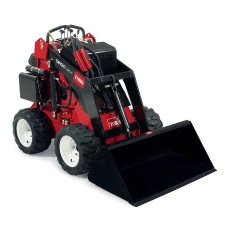
The loader is a four-wheel drive mini-loader. It contains:
• 3 or 4-cylinder diesel engine
• Hydrostatic travel drive system
• Multi-function operating handle
• 12 Volt electrical system
4.1.1 Engine and pump
The loader is powered with industrial engines, with four stroke cycle and direct injection. The engines are certified
by the manufacturer to meet the more advanced emissions standards.
W11/W12S,W13F Series loader has an automatically variable piston pump.
4.1.2 Motor and drive axle
The front and rear drive axles for the W11 are powered by two hydraulic motor cycloids, and the drive axle contains
differential, reduction gears and axles.
The back drive axle for the W12S/W13F is supplying power to the front drive axle through piston motor driving to
transmission axle.
The front and rear axle of the W13F wheel loader have the function of hub reduction, which can ensure good power
transmission. It also has differential lock, which allows machines to operate properly in poor working conditions.
4.1.3 Braking system
Hydrostatic drive can serve as a driving brake, and be installed on the input of the drive axle as a parking brake.
4.1.4 Wheels and tires
Four bolts are used to fix the tires on the drive wheel. The loader tires are of the pneumatic type which ensures a
smooth ride combined with maximum drawbar pull. Remember to check the pressure of your pneumatic tires
regularly. Uneven tire pressure will not only increase tire wear, but will also decrease tractive performance.
4.1.5 Fuel cell
The fuel cell is integrated in the front frame, and it is equipped with a filler cap and a fuel gauge.
4.1.6 Electrical system
The tractor uses a 12 Volt, automotive type, negative ground, electrical system. The system includes a 60/72 Ah
battery, ignition switch, two headlights, amber flashing light, turn signals, taillight, horn, various gauges and other
circuits.
Machine Tire size Rated pressure
W11 26x12-12AS 300 kpa
W12S 31x15.5-15AS 420 kpa
W12F
W13F/T13F 19.0/45-17 280 kpa

Page 13/81
April 2021W11 - W12S -W12F - W13F - T13F | Operation manual
4.1.7 Quick removal device
The demolition equipment from the accessories is controlled by a multi-port valve for quick assembly and
disassembly.
4.1.8 Seat
Seats of the loader with seat belts can be adjusted forward and backward. The seat class is EM8. As an option the
loader can be fitted with a comfortable suspended seat.
Driver's seat
The standard driver's seat can be adjusted to the driver's height and weight.
WARNING
Only adjust the driver's seat when the loader is at a standstill. The engine must be switched off.
Armrests
The armrests can be folded up as required and individually adjusted in
height. To adjust the armrests for height, separate the round cap (see
arrow) from the cover, loosen the hexagon nut (size 13 mm) behind it.
Adjust the armrests to the desired position (5-steps) and tighten the nut
again (25 Nm). Replace the cap onto the nut.
WARNING
When the belt roller is fitted, do not install the armrest in the lowest position, otherwise the belt roller might not
function correctly.
Carry out a functional test of the belt roller.
Backrest extension
The backrest extension can be individually adjusted for height by pulling it
upwards over the various increments up to the end stop. To remove the
backrest extension, pull it over the end stop.

Page 14/81
April 2021W11 - W12S -W12F - W13F - T13F | Operation manual
STANDARD SEAT (W13F)
Weight setting
The seat should be adjusted for the drivers weight by turning the weight
adjustment lever (1) with the driver sitting on the seat. The driver’s weight
is adjusted correctly when the adjusted height position of the height
adjustment handle (at the bottom of the handle) (2) is displayed in the
viewing window. The middle position of the spring travel of the respective
height adjustment is displayed. To prevent damage to health and material,
the setting for the driver's weight must be checked and adjusted
individually before the vehicle is driven.
Height adjustment
The height adjustment can be set to three settings (I, II, III). The respective
height must be set with the driver sitting on the seat. Turn the handle for
seat height adjustment to move the seat upwards or downwards. The seat
position displayed at the bottom of the handle for seat height adjustment
has been set.
I = lowest height position
II = middle height position
III = upper height position
Check and set the weight after every height adjustment.
Seat adjustment forward/backward
Seat adjustment to the front/rear is enabled by lifting the locking lever.
WARNING
Risk of accident!
• Do not operate the locking lever while driving.
• After the adjustment, the locking lever must latch into the desired position with an audible click. It should not
be possible to move the driver seat into another position when it is locked.
• Do not lift the locking lever with your leg or calf.
Fore/aft isolator
The fore/aft isolator improves the absorption of shock impacts (e.g. when
driving at high speed, in rough terrain or with a trailer attached) in the
driving direction by the driver’s seat.
The cushioning effect can be activated or deactivated with the help of the
locking lever.
1 = fore/aft isolator OFF
2 = fore/aft isolator ON

Page 15/81
April 2021W11 - W12S -W12F - W13F - T13F | Operation manual
The driver's seat is fitted with a safety belt (lap belt).
WARNING
• Always wear safety belts during work.
• Do not carry persons.
4.1.9 Multi-functional control handle
The control handle is on the right of the driver's position. As a standard, the switches on the device can control the
gears on the loader. There are three gears: forward, neutral, back and reset button. The handle can even operate a
two-way multi-channel valve, so lifting and tilting movements can be separated or merged.
For T13F model, front, rear, left, right (from driver’s direction) control handle operation correspond to lower, lift,
upper tilt and dump. It is same as other models. There are two buttons on the back of control handle. The upper or
lower key corresponds to the extension and retraction of the telescopic arm.
4.1.10 Cab
Cab door
The cab doors are to be kept locked during use. If required, the door can be
opened a crack. To do this, the lever shown in the illustration must be folded
out and locked in the door lock. On opening, the cab doors automatically
lock into the door lock. Release this lock to close the door.
Press the button Pull the lock

Page 16/81
April 2021W11 - W12S -W12F - W13F - T13F | Operation manual
CAUTION
• Lock the cab door after finishing work as well as on leaving the loader for longer periods, in order to prevent
unauthorized use of the machine.
• Always lock the doors in all positions. Open doors represent a danger as they swing open or closed.
Rear window
Swing both handles around at the same time, to open the rear window.
Heater
The cab is equipped with an infinitely variable heater. The adjustment lever
can be found on the right of the driver's seat. The switch for the ventilation
fan must be switched on.
To heat, the left switch must be set at least to "1".
Switch “a”: Fan levels
Switch "b": Temperature adjustment
Air-condition
The air conditioning system is switched on with left switch. The switch for
the ventilation fan must be switched on.
CAUTION
The air conditioning should be turned on once per month to ensure its operation.
Push both handles at the same time,
to open the rear window
Pull both handles at the same time,
to close the rear window

Page 17/81
April 2021W11 - W12S -W12F - W13F - T13F | Operation manual
Interior light (W13F)
Storage bins
A storage net is found on the behind of the driver's seat for the operating instructions.
WARNING
Always keep these operating instructions in this place to have them immediately available when if needed.
Battery isolating switch
This switch is used to disconnect the entire electrical system from the battery. If the machine is switched off for a
longer period of time, e.g. over night, the connection to the battery should be interrupted using the battery isolating
switch. In this ways the unintentionally discharging of the battery can be prevented. Push the lever down and turn
to switch on.
The lever can be removed when switched off. This provides additional protection against theft.
When the lever is removed the switch must be covered by the protective cap. This prevents moisture from
penetrating into the switch.
Warning buzzer
A warning buzzer is located on the rear of the steering column. It sounds when the engine is overheated. The engine
must then be shut off immediately. If the engine is not shut off immediately, this may damage the engine or other
parts of the machine.
On Off
Switched on Switched off

Page 18/81
April 2021W11 - W12S -W12F - W13F - T13F | Operation manual
Emergency exit
You should only climb onto and off the vehicle on the left-hand side of the vehicle, otherwise there is a risk of
unintentional operation of the swing arm. The right-hand side of the vehicle is only intended to be used as an
emergency exit.
Adjusting the steering column
The steering column can be adjusted in a longitudinal direction. To do this,
loosen the lever at the left. The steering column can now be tilted in a
longitudinal direction. Lock the steering column in the correct position with
the lever.
WARNING
Only adjust the steering column when the loader is at a standstill.
Parking brake lever
The parking brake lever is connected by a rod to the park brake drum mounted on the drive axle. (W11 is with foot
parking brake pedal, mounted lower left under the dashboard.)
The park brake is used for parking or holding the loader on grades and should always be set for parking and released
before driving. (If with foot parking brake pedal, press down by foot.) The brakes are engaged as the lever is pulled
toward the operator. Push the lever away from the operator (down) to release the brake. (If with foot parking brake
pedal, brake by pressing down by foot and press the pedal one more time to release the brake.)
On wheel loaders with two six-way valves, the changeover button on the joystick can also cause an electromagnetic
change in the oil in the attachment. Parking brake of W11 is installed to the left of the driver. This can be realized
while pressing the brake pedal by foot after stopping.
The mechanical auxiliary and parking brake is located on the power divider of the front axle. The brake is on the
front axle of loaders with an optional driving speed of up to 25 km/h and the models W12S/W13F. This brake is
designed as a multiple disk brake. The brakes are actuated hydraulically during travel.
To open the door, pull the small lever on the underside
of the lock towards you. This unlocks the lock.
The emergency exit is marked by
the stickers fixed alongside it.

Page 19/81
April 2021W11 - W12S -W12F - W13F - T13F | Operation manual
When the inch pedal is pressed, the brake piston is engaged via the brake cylinder. As a parking brake (hand brake)
the brake is operated mechanically via a pull cable. The parking brake can be adjusted with the cable. The driving
pump does not operate when the parking brake is applied. The loader cannot be moved.
WARNING
When using the parking brake as an auxiliary brake in an emergency, the lever must be pulled up very carefully so
that the brake cable does not tear.
4.1.11 Pedals
The accelerator pedal on the right of the driver is connected to the engine via a cable, which can control the engine
speed, so as to control the speed of the loader.
The foot brake pedal on the left of the driver is connected to the pump, which can control the oil supply, so as to
control the speed of the loader.
The throttle pedal is used to move the loader. The axial piston pump is swung out according to the diesel engine
speed and the driving speed thus automatically adjusted to the loader's load (automotive drive). The more the
throttle is opened, the faster the loader goes.
The automatic system is deactivated when the inch pedal is pressed. The further the pedal is pressed, the further
back the axial piston pump is swiveled. Thus, the force can be diverted from the traveling gear to the working
hydraulics at high diesel engine speeds or the loader can brake.
When the pedal is fully depressed, the axial piston pump is swiveled back to 0 and the multiple disk brake actuated.
The loader is braked and comes to a stop.
WARNING
Never brake sharply with a raised load or in corners. The loader could topple over.
4.1.12 Attachments
We offer different kinds of attachments with different functions:
The parking brake is released in position "A" Move to position "B" to apply the brake
Bucket
It can be used for spading, unloading bulk materials and working in short
distance. We offer different sizes of buckets to load and unload materials of
different density more efficiently.

Page 20/81
April 2021W11 - W12S -W12F - W13F - T13F | Operation manual
Forks
It can be used for spading, unloading large-block materials and working in
short distance.
Grass grab
It can be used for loading and unloading grass or hay.
Snow shovel
It can be used to clean the snow on the road and ground when it snows in
winter.
Soil auger
It can be used for drilling holes in the ground.
Sweeper
It can be used for sweeping and cleaning the ground.
Bale gripper
It can be used for gripping and transporting goods.
Other manuals for W11
3
This manual suits for next models
4
Table of contents
Other Eurotrac Compact Loader manuals
