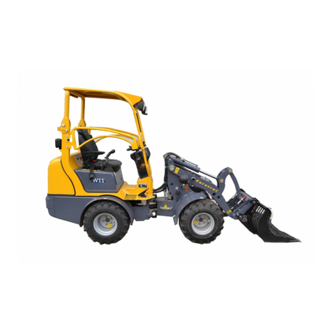
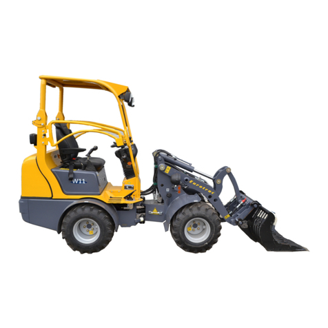
Eurotrac W11E User manual

P. de Heus en Zonen Greup B.V.
Stougjesdijk 153
3271 KB Mijnsheerenland
The Netherlands
Tel: +31 (0) 18 66 12 333
E-mail: info@eurotrac.nl
W11E WHEEL LOADER
OPERATION MANUAL

CONTENTS
W11E | Operation manual
1. SAFETY INFORMATION ............................................................................................................... 4
1.1 Revision record..................................................................................................................................... 4
1.2 General warning................................................................................................................................... 5
1.3 Information and operations ................................................................................................................. 7
1.3.1 Standard configuration ......................................................................................................... 7
1.3.2 Operator responsibility ......................................................................................................... 7
1.3.3 Mechanical responsibility ..................................................................................................... 9
2. GENERAL INFORMATION & OPERATING INSTRUCTIONS ........................................................... 10
2.1 Main components .............................................................................................................................. 10
2.1.1 Joystick for lifting frame ...................................................................................................... 18
2.1.2 Joystick for auxiliary hydraulics ........................................................................................... 19
2.2 Specifications and performance......................................................................................................... 24
2.3 Transport procedures......................................................................................................................... 27
2.4 Trailer procedure................................................................................................................................ 27
2.5 Stored procedures.............................................................................................................................. 28
3. MAINTENANCE PARTS .............................................................................................................. 29
3.1 General description............................................................................................................................ 29
3.2 General cleaning instructions............................................................................................................. 29
3.3 Service ................................................................................................................................................ 30
3.3.1 Preparation for use ............................................................................................................. 30
3.3.2 Regular maintenance form ................................................................................................. 31
3.3.3 Oil & Lubricant .................................................................................................................... 33
3.4 Troubleshooting ................................................................................................................................. 35
3.4.1 Kinetic energy reduction ..................................................................................................... 35
3.4.2 Drive axle ............................................................................................................................ 36
3.4.3 Brake system ....................................................................................................................... 37
3.4.4 Lithium battery .................................................................................................................... 38
FIGURE 1: W11E HYDRAULIC SCHEMATIC .......................................................................................... 39
FIGURE 2: ELECTRICAL SCHEMATIC .................................................................................................... 40
FIGURE 3: BODY LOGO LAYOUT ......................................................................................................... 41
DAILY EQUIPMENT INSPECTION ........................................................................................................ 42
4. SME ELECTRONIC CONTROL SYSTEM ........................................................................................ 43
4.1 About warning, caution and information notices .............................................................................. 43
4.2 Troubleshooting and fault codes........................................................................................................ 44
4.2.1 Fault levels .......................................................................................................................... 44
4.2.2 Fault list ............................................................................................................................... 44
5. AC SMARTMOTION AC-M2 OVERVIEW ..................................................................................... 51
5.1 Product description ............................................................................................................................ 51
5.1.1 Product Indication Label .................................................................................................... 52
5.2 General Specifications ....................................................................................................................... 52
5.3 Electrical Specifications ...................................................................................................................... 53
5.3.1 Input and Output Ratings .................................................................................................... 53
5.3.2 Signal: Inputs and Outputs ................................................................................................. 53
5.3.3 Interfaces ............................................................................................................................ 55

CONTENTS
W11E | Operation manual
5.3.4 EMC ..................................................................................................................................... 55
5.3.5 Safety .................................................................................................................................. 55
5.4 Operating Environment Specifications .............................................................................................. 55
6. INSTALLATION AND WIRING ..................................................................................................... 56
6.1 Controller ........................................................................................................................................... 57
6.2 Power Terminals................................................................................................................................. 59
6.3 Main contactor................................................................................................................................... 60
6.4 Fuse .................................................................................................................................................... 61
6.5 Signal ................................................................................................................................................. 62
6.5.1 Digital Inputs ....................................................................................................................... 63
6.5.2 Analog Inputs ...................................................................................................................... 64
6.5.3 Driver Outputs (PWM) ........................................................................................................ 65
6.5.4 Digital Outputs (ON/OFF) .................................................................................................... 66
6.5.5 Speed Sensor Inputs ............................................................................................................ 67
6.5.6 Thermal Probe .................................................................................................................... 68
6.5.7 Serial ................................................................................................................................... 68
6.5.8 CAN Network ....................................................................................................................... 69
6.6 SME external devices description ...................................................................................................... 70
6.6.1 Encoder ............................................................................................................................... 70
6.6.2 Displays ............................................................................................................................... 71
7. GRAPHICAL INTERFACE ............................................................................................................. 72

Page 4/72
October 2019W11E | Operation manual
1. SAFETY INFORMATION
1.1 Revision record
Due to the continuous improvement and innovation of product design, the product changes; this manual might not
include these latest changes. Upon request we can send you the latest version of the manual.
We reserve the right to make improvements and changes to the loader of a model on our own products without any
representation.
If you need more maintenance information outside of this manual, please contact your EUROTRAC dealer.
Issue date:
Update number Disassembly Load Replacement instructions

Page 5/72
October 2019W11E | Operation manual
1.2 General warning
Foreword
These operating instructions apply to all users of the loader: company manager, department head, driver and other
personnel associated with or working near the loader.
WARNING
1. Read this manual and follow the instructions in the manual before using the loader.
2. Read the instructions on the loader carefully and keep the text legible.
3. All operators must read this manual.
4. All personnel qualified to use the loader can operate the loader in accordance with safe use regulations.
5. When the machine is idle, do not let other people touch the machine.
6. Do not use if the loader does not work properly.
7. Do not use the loader for work that exceeds its maximum load or maximum capacity.
8. Do not use the loader to perform work beyond its scope of use.
9. Be familiar with the safe operating rules associated with using this loader and follow the rules exactly.
10. The manufacturer assumes no responsibility for the consequences of dismantling or modifying the loader.
Obligation to read the manual
The company manager must familiarize the operator with the operating rules of
the manual.
Read the entire chapter before attempting to operate the loader. It is the
responsibility of the company manager to ensure that the operating rules in the
manual are implemented. The operator must read and be familiar with the
instruction manual so that it can be operated in accordance with the rules when
starting and using the loader. This instruction manual should be kept intact during
the life of the loader, even if the machine is resold, replaced by the user or
manager, etc.
This manual is not a training manual, but it can also be used as one of the training
materials if it is really necessary to train the operator.
General instructions
The company manager must ensure that the operating manual (including the
certificate of conformity issued by the European Community) is delivered with the
loader.
• When the product leaves the factory, the manual will be included.
• The product certificate is sent along with the shipping order. Under the
authority of the company manager, the trained personnel and the person
with the relevant driver's license can operate the loader and the operation
must not exceed the scope of the machine design. The loader must be
operated in accordance with the conditions specified by the manufacturer in
the operating manual. The manufacturer will not be liable for any personal
injury, property damage and environmental pollution caused by failure to
follow the procedures specified in the instruction manual. The
manufacturer's responsibility is to match the assembly structure of the
machine to the instructions in the certificate of conformity. Before each use,
the driver should check that the machine is all right. It is forbidden to use the
loader without checking the machine and without checking the warning
decals.

Page 6/72
October 2019W11E | Operation manual
Loader normal use range
W11E Electric Loader – Maximum allowable load and general conditions of use are included in this document.
Do not use the loader to load anything other than the scope of use. This loader is suitable for use in the temperature
range - 30 °C - 45 °C
Users should not ignore this rule: EUROTRAC is not responsible for all the dangers and injuries caused by this.
Loader modification
The manufacturer does not assume any responsibility for the modification of the loader and the addition of
accessories by equipment not manufactured by Eurotrac. The manufacturer assumes no responsibility for the
consequences of the replacement or modification of the machine's features or other mechanical, electrical,
hydraulic-related accessories or mechanically welded structures without the written consent of the manufacturer.
If the customer needs to modify the machine, please consult the manufacturer. For your safety and your ability to
benefit from all warranty terms of manufacture, use spare parts manufactured and warranted by the manufacturer.
Notice
Safe operation is very important to your personal safety and economic efficiency, which means that we have a
responsibility to promote safe operation knowledge. EUROTRAC has always regarded product safety as its
responsibility, so we pay great attention to the safety of the loader when designing the loader for you.
Your job is to operate safely. The safety of you and others depends on your competent operations, especially on
your understanding of the following brief safety rules and voluntary compliance.
Security Information
This manual provides you with some important information to help you familiarize yourself with the safe operation
and maintenance of the EUROTRAC loader. Even if you are familiar with the operation of a vehicle similar to a wheel
loader, you must read and become familiar with this manual before operating this loader. Safe operation is
everyone's responsibility and therefore your primary responsibility. Knowing the operating instructions in this
manual will ensure the safety of you and the staff around you.
Safety is a very important part that affects the life of your loader. Read and study this manual before you operate,
maintain or otherwise use this loader to know how to safely use the controls of the loader and the safety
maintenance you must do. If you have any questions about the safe use or repair of the loader, ask your boss - don't
guess - check often!
Remember that a careful driver will not only protect himself, but also protect his colleagues at work; at the same
time he will avoid the danger of damaging the loader and cargo at work.

Page 7/72
October 2019W11E | Operation manual
1.3 Information and operations
1.3.1 Standard configuration
Standard loaders have the following features:
1. Travel motor
2. Power Steering
3. Electromagnetic parking brake
4. Electronic shift control
5. Multi-function hydraulic control handle
6. Attachment quick change and locking mechanism
7. Adjustable shock seat (seat belt)
8. Lift arm / boom
9. Non-slip flooring
10. Combination LED headlights
11. Roll cage with sunshade cover
12. Direction indicator
13. Work light
14. Combination meter
15. Adjustable steering wheel
16. Double ball joint hinge
17. SME Controller
18. 51.1V 400Ah Lithium battery
1.3.2 Operator responsibility
You must read this chapter and thoroughly understand it, then operate or perform any maintenance on the device.
WARNING
Failure to observe the following safety precautions can result in serious injury or death, as well as equipment
damage.
1. Always follow global safety rules in your field.
2. Always check for proper operation and lighting, brakes, steering, parking brakes, parking brakes and tires
before using this loader.
3. Do not operate the loader with defective features; refer to the operation and service manual of the
maintenance section.
4. Always wear suitable shoes when handling the device and avoid loose clothing that may get stuck in moving
parts.
5. Before use of the loader, fasten the seat belt and confirm that the lock is fastened.
6. After the loader has completely stopped, place the gear in the neutral position. Before leaving the loader, turn
off the power and pull out the key.
7. Wait until the vehicle stops completely before the transition goes from forward to backward or from back to
forward.
8. Check the road after reversing.
9. When loading materials, the speed should be reduced to 5KM/H.
10. Raise the bucket to the transport position (minimum ground clearance greater than 20cm).
11. Be extremely careful when in crowded areas and near blind roads and trucking. Be alert to other devices and
people.

Page 8/72
October 2019W11E | Operation manual
12. Do not operate if the speed does not meet the operating conditions. Always limit the speed to ensure you have
enough time to brake in an emergency.
13. Do not use the loader to shovel dangerous goods.
14. Before using this loader, the roll cage must be raised and the latch in the locked position.
15. Do not allow any form of traction on the loader other than the towing hook.
16. Do not perform repairs while the motor is running hot, as this can result in severe burns. Please perform
maintenance after cooling.
17. Do not attempt to touch the running motor and pump motor that is running or just stopped, otherwise it will
cause severe burns.
18. After the hood back cover is opened, make sure to not use clean water or other liquids since they can splash
into the controller and the battery causing a short circuit.
19. Do not use the battery of this car to start other vehicles.
NOTE
When the vehicle is tilted or rolled over, do not jump, but hold on tight to the steering wheel.
NOTE
The roll cage damaged by rollover is not allowed to be repaired and reused unless it is authorized or approved by
EUROTRAC.
NOTE
The rated working load calibrated in this manual is based on the ground level of the machine. When operating on
non-standard road surfaces (such as soft, uneven roads or on slopes), the effects of these factors on the load should
be fully considered.

Page 9/72
October 2019W11E | Operation manual
1.3.3 Mechanical responsibility
You must read this chapter and thoroughly understand it before performing any maintenance on the device.
WARNING
Failure to observe the following safety precautions can result in serious injury or death, as well as equipment
damage.
1. Always follow local safety regulations.
2. The operator must be familiar with the operation of the machine before using it.
3. Always keep your hands and feet away from rotating parts and tires, and wear safety uniforms.
4. Always wear the right shoes when handling or servicing equipment. Avoid wearing loose clothing, which may
get stuck in moving parts.
5. Always ensure the cleanliness of the controller cooling fan.
6. Do not start the machine in an explosive environment.
7. Do not check gear oil when the motor is running.
8. Always disconnect the main power switch of the lithium battery when working on the travel motor.
9. If the lithium battery is overheated or abnormally discharged, do not attempt to perform repairs in private.
Please contact a professional for repair.
10. Do not touch the oil pump motor and the travel motor when it is hot, otherwise it will cause severe burns.
11. Do not smoke near a lithium battery. Always keep the lithium battery away from sparks, flames and smoking.
12. Always remove the metal bracelet, watch strap, etc. before installing, removing or maintaining the lithium
battery.
13. Do not allow short circuit lithium battery terminals.
14. When connecting a lithium battery, always connect the positive terminal first to prevent sparks.
15. Check all lights.
16. Check the reverse warning alarm.
17. Make sure the machine is in neutral when starting. Put the seat, handlebars and mirrors in the correct position
before use.
18. Check tire and wheel conditions for proper inflation pressure. Excessive inflation can cause tires to explode.
19. Tighten the rim nut to a torque of 130 ft-lbs. Check the torque after 5 hours of operation.
20. Use appropriate lifting equipment when removing or replacing heavy parts.
21. When working under the loader, make sure that it is properly supported on the safety crane. Not completely
dependent on hydraulic jack support loader.
22. If the loader is raised under a hydraulic or air lift, ensure that the loader has a secure support or fixed position
before working under the loader.
23. When checking or repairing the drive system failure, jack up the drive wheel.
24. Do not smoke when injecting oil.
25. Do not use the lithium battery of this car to start other vehicles.

Page 10/72
October 2019W11E | Operation manual
2. GENERAL INFORMATION & OPERATING INSTRUCTIONS
2.1 Main components
The W11E is a four-wheel drive mini loader. It contains:
• Hydraulic motor
• Travel motor
• Multi-function operating handle
• 12 volt electrical system
• 51.1V400Ah lithium battery
Travel motor
The loader is equipped with a powerful mobile motor that is certified by the
manufacturer to meet the job requirements and environmental requirements for
zero emissions.
Drive axle The rear axle of the W11E is driven by the travel motor and then transmitted by
the drive shaft to the front drive axle.
Brake system This wheel loader brakes on the front axle and driving engine by pressing the
brake pedal.
Wheels and tires
The loader tires are pneumatic and are able to travel smoothly and effectively
maximize traction. Remember to check the pressure on your pneumatic tires
regularly.
Unbalanced tire pressure will not only increase tire wear, but also reduce traction
performance.
W11E tire model: 26x12-12AS Tire pressure: 3.0bar
Electrical System
The loader uses a 12 volt, automatic type, negative ground electrical system. The
system includes a 51.1V400Ah lithium battery (see battery instruction manual for
specific parameters), ignition switch, two headlights, amber flash, direction lights,
taillights, speakers, various meters and other circuits.
Quick disassembly device The attachment of the attachment is controlled by a multi-way valve for quick
assembly and disassembly.
Seat The seat of the loader is equipped with a seat belt and can be adjusted back and
forth. The seat rating is EM8 (optional).
Battery charger The loader is equipped with an integrated 220V battery charger with charging
indicator. Max. loading time 6 hours
Multi-function joystick
The joystick is located to the right of the driver's position. As a standard, the
switch on the device can control the gear position of the loader. There are 3 gear
positions: forward gear, neutral gear and reverse gear, and reset button. The
handle can also control two multi-way valves, so that lifting and tilting can be
performed separately or in combination.
Parking brake
The electric driving motor is equipped with a parking brake drum. After the
vehicle stops for a few seconds, the electronic control motor is powered off, and
the brake is automatically locked.
Pedal
The accelerator pedal on the right side of the driver is connected to the controller
via wires to control engine speed and thus control the speed of the loader The
inching pedal on the left side of the driver is connected to the front axle brake
drum via the brake hose to control the speed of the loader.

Page 11/72
October 2019W11E | Operation manual
NOTE
It is important that the operator adjusts the seating position and gets familiar with the controls before starting to
work.
NOTE
The root mean square value of the vibration acceleration of the machine acting on the arm is less than 2.5m/s2.
The root mean square value of the vibration acceleration of the machine acting on the whole body is less than 0.5m/s2.
Steering wheel
The operation of the steering wheel is the same as usual, that is, when the
steering wheel is rotated to the right, the loader turns to the right, and when the
steering wheel rotates to the left, the loader turns to the left.
Instrument panel Design control panel combined with the best driving comfort and efficiency.
Switch
Ignition switch Waterproof ignition switch for loader, including anti-restart function.
Horn control switch Mounted on the underside of the instrument panel.
Headlight switch Mounted on the underside of the instrument panel.
Warning light switch Mounted on the underside of the instrument panel.
Parking brake switch Mounted on the underside of the instrument panel.
Turning signal switch Mounted on the left handle of the instrument panel.
Far and near light switch Mounted on the left handle of the instrument panel.
Wide light switch Mounted on the left handle of the instrument panel.

Page 12/72
October 2019W11E | Operation manual
SME Dashboard
Wheel loader travel speed (km/h)
Hand brake switch.
This indicator lights when the hand brake is pulled up.
Safety seat switch.
If the seat switch is not closed, the dashboard will display the seat icon.
The seat switch does not pull in and the wheel loader cannot work until the seat
switch is closed.
Working hour meter (odometer).
Steering angle showing the position of the rear wheel.
Maintenance time prompt.
Prompt the user to the maintenance time.
Slow operation.
This light is on, indicating that the vehicle is operating in the slow mode, and the
speed and lifting speed are reduced.
Accelerator pedal position (0 to 9 grids).
Motor temperature overheat alarm.
Battery power is indicated by 9 stripes:
9 = Fully charged
0= Empty
If the battery is completely discharged there is no stripe showed and the
meter will display fault code 12.
The battery must be charged when the display shows one stripe.

Page 13/72
October 2019W11E | Operation manual
There are four LED indications on the left side of the instrument cluster. When the switch is operated, the
corresponding indicator will be displayed:
Instrument working process and instructions for use:
1. Turn on the key switch; the dashboard is switched on, some initial digital mode will be displayed for 3 seconds.
The dashboard states the speed indication content, the power indicator, the steering angle indication, the hand
brake indication, the seat switch indication, the E/S/H selection indication, the working time, and the like.
These pattern data will help confirm the vehicle's working status.
2. The top of the left row of the LCD screen is the fault indication. When this indicator is on, the following three
working states are displayed:
- Display normal operation (lights when the system switch is on or off).
- The meter is not connected to the control box (the indicator lights up after the connection stops for 3
seconds).
- The meter is not working (the indicator is on).
When the vehicle is working normally, there is no fault code and the fault light is off.
3. When the direction indicator is turned forward and backward, the left and right turn mark lights flash, and
when the headlights are turned on, the light indicator lights.
By pressing the E-S-H button, you can set the operating mode for your system (E-
Economy, S-Middle Mode, H-High Mode)
H-up mode: At this time, the acceleration, deceleration rate and maximum grade of
the vehicle are higher. It is suitable for transporting a large amount of cargo and
climbing a steep slope in a short time, but it costs electricity, unless it is urgently
needed, it usually does not work in this mode.
S-mid-range mode: Each indicator is slightly lower than the high-end mode.
E-Economy: All parameters are optimized, power saving, it is recommended to work
in this mode.
1. When the key switch is activated, press the enter button for 3 seconds to enter
the adjustment and diagnosis mode.
2. During the operation, press for 3 seconds to enter the diagnostic mode.
3. If you press enter once in the diagnostic mode, you can exit, and the enter key
is usually used as the new parameter value.
1. Press this button to decrease the parameter value in the adjustment or
diagnosis mode.
2. In the adjustment state, the display parameter value can be reduced.
3. Press the button for 1 second to display the mileage or weight.
Note: The up button is the same as the down button. Some functions of the enter
button and the up and down buttons are not activated.
Warning sign: LED shows red
Light identification: LED display green
The steering switch is turned on, the turn signal indicator is activated, and the LED
flashes green.
Brake fluid low: LED red alarm (optional)

Page 14/72
October 2019W11E | Operation manual
4. Brake display. When the parking brake is used, the graphic [P] light is on; when the parking brake is released,
the marker light is off.
NOTE
When the power indicator only shows one dash, it must be charged to extend the battery life.
Working environment:
1. The altitude does not exceed 1200 meters.
2. Working environment temperature -25 °C ~ +40 °C.
3. The maximum relative humidity is not more than 95%.
Precautions:
1. The dashboard is prohibited from water dripping. When the user washes the vehicle, be careful not to spray or
sprinkle water onto the inside of the instrument. If water is accidentally drenched onto the surface of the
instrument, immediately wipe it off with a dry cloth.
2. Do not plug or unplug the dashboard and the harness frequently to avoid loose contact.
3. It is forbidden to strongly impact and scratch the instrument.
4. If the instrument is not working properly, please contact the company in time for maintenance.
BEFORE DRIVING
• Be sure that all driving parts are in good working condition and fill all the fluid levels if necessary. Any defect or
failure has to be repaired before use.
• Set parking brake
• Walk around and inspect the loader for damage or missing equipment
Check for:
- Pressure and the good state of the pneumatic tires
- Look for cuts, cracks in side walls, foreign objects in treads
- Look for loose wheel nuts - Damage to lights
- Fire extinguishers fully loaded and in place (if have)
• Check to see if hydraulic or lubricating oil is leaking. If leaks are detected, they must be repaired as soon as
possible.
• Check the amount of fluid in the hydraulic tank to make sure there is enough hydraulic oil. If there is a very low
liquid level display, there is a serious leak in the system and it should be repaired as soon as possible.
• Check the power cabin for loose components, loose wires or equipment leaks.
• When all mechanical checks are completed, check that the stop lights and rear lights and dashboard lights are
working properly.
• Check the electricity meter to make sure the lithium battery power is sufficient.
• Make sure the roll cage is raised and locked firmly.
• Check if the driver's seat is damaged (replace the damaged one) and adjust the driver's seat according to your
needs.
• Check all operations in the work order.
NOTE
The battery life will be damaged if the battery is undercharged. The battery should be charged after daily work to
ensure that the battery is fully charged.

Page 15/72
October 2019W11E | Operation manual
DRIVING INSTRUCTION
• Place shift lever in park.
• Adjust the driver seat and steering wheel to the comfortable
location, fasten the seat belt.
• Make sure parking brake is set.
• Verify that nobody and nothing is ahead of you BEFORE starting
any motion of the wheel loader.
• Turn on the main power switch located at the left side, behind
the seat. Turn this for 3 seconds to the left till the green light
turns on (see picture).
• Turn on the ignition switch on the side of the dashboard.
• Release the handbrake by pressing the button on the dashboard.
• Move the transmission shift lever into the required position, Forward or Reverse.
• Press the acceleration pedal slowly with your feet. The wheel loader will move to the selected direction.
• To slow the wheel loader, slowly release the accelerator pedal and press the left brake pedal. For an emergency
stop, release the accelerator pedal and press brake pedal. By releasing the accelerator pedal slowly or quickly,
the wheel loader can be controlled by flat or sharp braking. Press the left-pedal when emergency brakes.
NOTE
The main power switch will turn of automatically when there is nobody on the driver seat for longer than 60
seconds.
CHARGING THE BATTERY
The Eurotrac W11-E comes standard with a built-in 220V battery charger. With the supplied cord it is easy to
connect to the machine and charge via a 220V connection. The status of the battery can be easily seen on the load
indicator.
Red = less than 80% | Yellow = 80% | Green = 100% loaded |Max loading time = 6 hours

Page 16/72
October 2019W11E | Operation manual
WARNING
The maximum duration of control for an operator should not exceed 6h per day.
WARNING
Match driving speeds to loads being towed and weather conditions. Slow down when towing heavy loads and when
road surface is wet or icy, especially on grades.
WARNING
When loading the goods, the speed should be lowered to 5km/h and the bucket should be raised to the
transportational position (about 20cm from the ground).
WARNING
In the course of ramping on the road (uphill) for the temporary parking, drivers are not allowed to leave the driver's
seat and change gear switch. Right foot should press the micro-pedal gently to remove any slipping phenomenon
due to technical reasons. At the same time pull up hand brake. Downhill for the temporary parking. Drivers are not
allowed to leave the driver's seat and switch to a reverse gear shift, right foot should press the micro-pedal gently
and park slowly, at the same time pull up hand brake.
WARNING
Parking on the ramp is not allowed. If necessary the car should be parked on a slope (due to breakdowns), you must
pull hand brakes and pad the wedge under wheels of the loader.
WARNING
Make sure the roll cage arises and fixed before driving, it can‘t protect the driver if the roll cage don‘t arise or fixed
insecure.
LOADING INSTRUCTION
• Lift devices and attachments (bucket is standard) are only used for a specified purpose.
• Ensure the wheel loader is secure and is within the rated drawbar pull of the loader (See “General preventive
measures“).
• Ensure the rapid removal device in a locked position before filling.
• When driving with a load, the speed should be reduced to 5 km/h.

Page 17/72
October 2019W11E | Operation manual
• When driving with a load, the bucket should be raised to the transformational position (about 20cm from the
ground).
• When driving on the ramp, goods shall be towards the uphill direction. U-turns and parallel driving on ramps
must be avoided.
• Only operate the machine when having clear and unobstructed view.
• When uninstalling, raise the bucket to an appropriate height, as carefully as you can accurately to drive the
wheel loader to the truck or the place for goods storage; Carefully control the master control lever, uninstall,
reset; Confirming that the bucket and the truck (shelf) is completely separated, the loader moves slowly back
to leave the shelf.
• When reaching the parking spot, shift it into neutral position, raise the parking brake, and turn off the ignition
switch.
NOTE
Safe and efficient loading, depends entirely on the operator. If you are an experienced driver, the following rules
will refresh your memory. If you are a student, they will help you to become a professional driver.
WARNING
Only qualified and licensed drivers allowed to drive.
WARNING
Before starting loading, please make sure the cylinder of the quick removal device is in the locking position, set the
locking tools, and cut the two-way ball valve off.
WARNING
When driving on the ramp (forward or backward), goods shall be towards the uphill direction. Driving or u-turn
ramping on the horizontal should be avoided.
WARNING
When the goods are in a lifting state, do not leave the loader.
WARNING
When the goods are in a lifting state, the loader can not turn around and can not run at high speed.

Page 18/72
October 2019W11E | Operation manual
2.1.1 Joystick for lifting frame
WARNING
Accident hazard due to wheel loader tipping! Keep the lifting frame lowered during transport.
Accident hazard due to uncontrolled lifting frame movement!
Only operate the lifting frame and attachment from the driver's seat!
Always work calmly and cautiously. Hectic and rapid operation leads to accidents.
Always lower the lifting frame during interruptions and at the end of the shift.
Lifting frame movements are controlled by the joystick. The joystick
is located to the right of the driver's seat.
Lifting frame
• Move the joystick backwards: the lifting frame rises.
• Move the joystick forwards: the lifting frame lowers.
• Move the joystick 2 step forwards: the lifting frame is now in the
floating position (optional extra).
Attachment
• Move the joystick left: the attachment tips inwards.
• Move the joystick right: the attachment tips outwards.

Page 19/72
October 2019W11E | Operation manual
2.1.2 Joystick for auxiliary hydraulics
WARNING
Hazard due to hydraulic system overheating! Ensure that the auxiliary hydraulics joystick is always in the "zero
position" when the auxiliary hydraulics are not required. Lock the auxiliary hydraulics joystick when it is not
required. (To do this, press the joystick down firmly until it locks into place. To unlock, you must pull the joystick
back up firmly.) Avoid soiling. Ensure that the hydraulic connections are clean!
The additional hydraulics on the front arm: press the auxiliary hydraulics button and move the joystick to the left
and right. The auxiliary hydraulics can be very precisely controlled. Take care to use the joystick carefully.
• Push the joystick to the left (and simultaneously press the auxiliary hydraulics button):
The left connection is the pressure side, the right is the return.
• Push the joystick to the right (and simultaneously press the auxiliary hydraulics button):
The right connection is the pressure side, the left is the return.
This may vary from model to model. Please always check this before using the wheel loader with optional
equipment.
Auxiliary hydraulics
This can be operated using an additional lever with switching valve. Let yourself be instructed by qualified personnel
and complete this manual here.
Replace attachment
1. Push the small handle of multi-way valve to the left to retract the locking lever.
2. Lower the working device and tilt it forward to the appropriate position.
3. Connect the hook in the attachment.
4. Hoist and tilt working device.
5. Push the small handle of the multi-way valve to the right to make the locking lever extend and insert the
mounting hole under the fitting.
6. The two three-way valve rotates 90°, cut off the lock cylinder oil.
Eurotrac W11 Eurotrac W12/W13

Page 20/72
October 2019W11E | Operation manual
Remove the attachment
The step is reversing as changing attachment step.
WARNING
Lifting devices and tools are only used for a specified purpose. Drivers must comply with the correctly and use the
lifting devices and tools. Do not enter or reach into the space between the arm and the frame.
WARNING
Before the operation of hydraulic systems, check if the functions of the various hydraulic joysticks are correct.
WARNING
Before disassemble the pipe of attachment, should release the rest pressure of this pipe, then disassemble the quick
change connector. The detailed method of release rest pressure is: swing the first valve handle (small handle) of
multi-valve left and right side several times.
WARNING
Even if the engine flameout can also lower the lifting devices and tools.
WARNING
If the tool is not delivered together with the loader, it can be only used after the authoritarian of stability and load
capacity by the dealer of EUROTRAC.
General preventive measures
• Do not operate any levers or pedals if anyone is in any position to be hurt by the machine's movement.
• Pay extra attention when working in narrow congested areas or in case of blind travel.
• Always look around in all directions BEFORE changing your direction of travel.
• Always follow all safety rules or each particular site during operation.
• Maintain a running speed which is compatible with the load and the ground conditions.
Table of contents
Other Eurotrac Compact Loader manuals
