Eurotron Mini MMX II User manual

Mini MMX II
Professional Multimeter
Multimetro Professionale
Instruction Manual MM850592 ed. 01
Manuale d'uso MM850592 ed. 01
ENGLISH
ITALIANO
¡ã
10A
A
mA
V
Ω
¡ã¡ã
μ
¡ã
F
C
REL
AC
Hz%
DC
AUTO
Hz%
kM
F
C

MM850592 ed. 01 - Mini MMX II
2
INTRODUCTORY NOTE
This manual has been with all the information you need to install, operate and maintain the instrument.
Eurotron has used the best care and efforts in preparing this book and believes the information in this
publication are accurate. The Eurotron products are subjected to continuous improvement, in order to
pursue the technological leadership; these improvements could require changes to the information of this
book.
Eurotron reserves the right to change such information without notice.
Any maintenance operation must be carried out by qualified personnel only. Eurotron supplies instructions
and operative procedures for any operation on the instrument. We recommend contacting our technicians
for any support requirements.
The instrument is fully tested in conformity with the directive n°89/336/CEE Electromagnetic Compatibility.
Eurotron shall not be liable in any event, technical and publishing error or omissions, for any incidental and
consequential damages, in connection with, or arising out of the use of this book.
The operator must not use this equipment for any other purpose than that stated.
This document is the property of Eurotron and may not be copied or otherwise reproduced, communicated
in anyway to third parties, not stored in any Data Processing System without the express written authority of
Eurotron Instruments S.p.A.
All rights reserved
Copyright © 2006
Eurotron Instruments SpA
Viale F.lli Casiraghi 409/413
20099 Sesto S. Giovanni (MI)
Tel. : +39-02 24 88 201
FAX: +39-02 24 40 286
Mail: info@eurotron.com
MM850592 ed. 01 - Mini MMX II
3
SAFETY INFORMATION
The following safety information must be observed to insure maximum personal safety during the operation
at this meter:
•Do not use the meter if the meter or test leads look damaged, or if you suspect that the meter is not
operating properly.
•Never ground yourself when taking electrical measurements. Do not touch exposed metal pipes,
outlets, fixtures, etc., which might be at ground potential. Keep your body isolated from ground by
using dry clothing, rubber shoes, rubber mats, or any approved insulating material.
•Turn off power to the circuit under test before cutting, unsoldering, or breaking the circuit. Small
amounts of current can be dangerous.
•Use caution when working above 60V dc or 30V ac rms. such voltages pose a shock hazard.
•When using the probes, keep your fingers behind the finger guards on the probes.
•Measuring voltage which exceeds the limits of the multimeter may damage the meter and expose the
operator to a shock hazard. Always recognize the meter voltage limits as stated on the front of the
meter.
•Never apply voltage or current to the meter that exceeds the specified maximum:
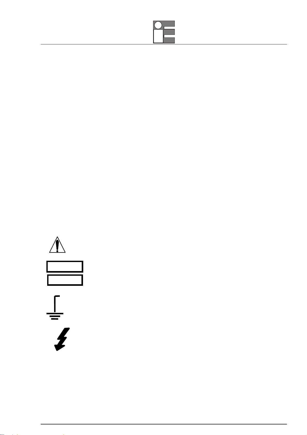
SAFETY SYMBOLS
This symbol adjacent to another symbol, terminal or operating device indicates that
the operator must refer to an explanation in the Operating Instructions to avoid
personal injury or damage to the meter.
This WARNING symbol indicates a potentially hazardous situation, which if not
avoided, could result in death or serious injury.
This CAUTION symbol indicates a potentially hazardous situation, which if not
avoided, may result damage to the product.
This symbol advises the user that the terminal(s) so marked must not be connected
to a circuit point at which the voltage with respect to earth ground exceeds (in this
case) 1000 VAC or VDC.
This symbol adjacent to one or more terminals identifies them as being associated
with ranges that may, in normal use, be subjected to particularly hazardous voltages.
For maximum safety, the meter and its test leads should not be handled when these
terminals are energized.
WARNING
CAUTION
MAX
500V
MM850592 ed. 01 - Mini MMX II
4
36
¡ã
9
10
8
4
10A
A
mA
V
Ω
¡ã¡ã
μ
¡ã
F
C
11
12
7
REL
1
2
AC
Hz%
DC
AUTO
Hz%
kM
F
C
5
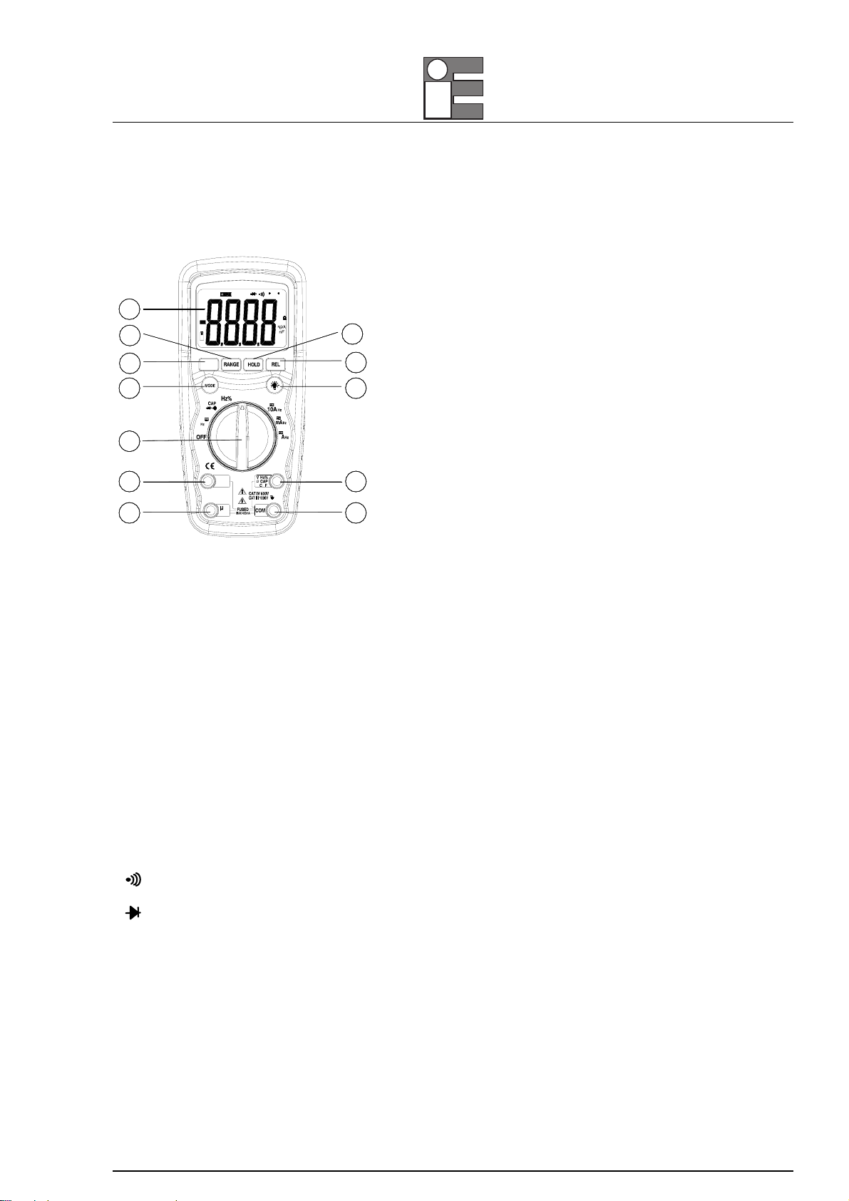
CONTROLS AND JACKS
1. Large 4000 count Liquid Crystal Display with symbolic signs.
2. Range pushbutton.
3. Frequency/ %Duty button.
4. Mode pushbutton.
5. Data Hold pushbutton
6. Relative pushbutton.
7. Backlight pushbutton.
8. Function switch
9. 10A (positive) input jack for
10. uA/mA input jack
11. Positive input jack for DC/AC Voltage, Hz/ %duty cycle, Ohms, Diode, Continuity, Capacitance,
Temperature (°C or °F) measurements
12. COM (negative) input jack.
SYMBOLS AND ANNUNCIATORS
Continuity
BAT Low Battery
Diode
DATA HOLD Data Hold
AUTO AutoRanging
AC Alternating Current or Voltage
DC Direct Current or Voltage
MM850592 ed. 01 - Mini MMX II
5
SPECIFICATIONS
The instrument complies with: EN61010-1.
Insulation: Class2, Double insulation.
Overvoltage category: CATIII 1000V, CATIV600V.
Display: 4000 counts LCD display with function indication.
Polarity: Automatic, (-) negative polarity indication.
Overrange: “OL” mark indication.
Low battery indication: The “BAT” is displayed when the battery voltage drops below the operating level.
Measurement rate: 2 times per second, nominal.
Auto power off: Meter automatically shuts down after approx. 15 minutes of inactivity.
Operating environment: 0°CC to 50°C (32°F to 122°F) at < 70 % relative humidity.
Storage temperature: -20°C to 60°C (-4°F to 140°F) at < 80 % relative humidity.
For inside use, max height: 2000m
Pollution degree: 2
Power: One 9V battery , NEDA 1604, IEC 6F22.
Dimensions: 182 (H) x 82 (W) x55 (D) mm
Weight: Approx.: 375g.
Accuracy is given at 18°C to 28°C (65°F to 83°F), less than 70 % RH
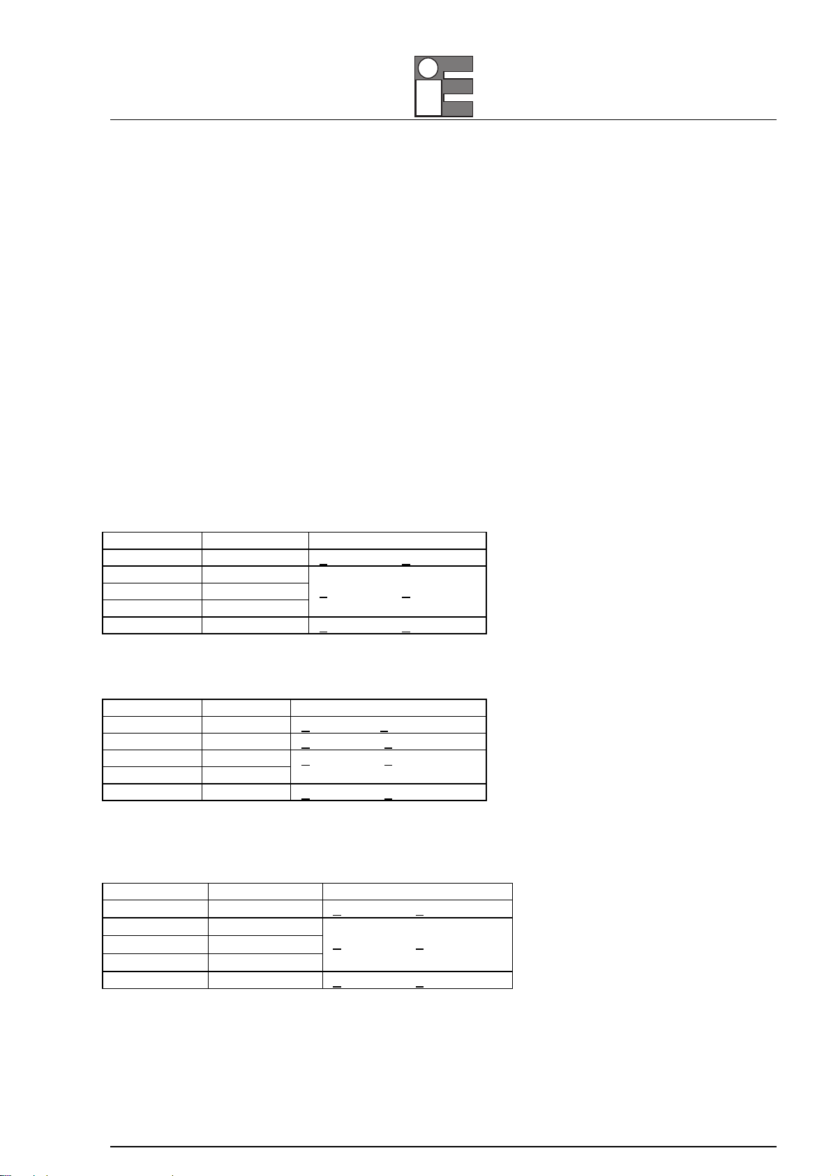
DC Voltage (Auto-ranging)
Range Resolution Accuracy
400.0mV 0.1mV +0.5% of rdg + 2 dgts
4.000V 1mV
40.00V 10mV
400.0V 100mV
+1.2% of rdg + 2 dgts
1000V 1V +1.5% of rdg + 2 dgts
Input Impedance: 7.8MΩ.
Maximum Input: 1000V dc or 1000V ac rms.
AC Voltage (Auto-ranging except 400mV)
Range Resolution Accuracy
400.0mV 0.1mV +1.5%of rdg + 70 dgts
4.000V 1mV +1.2% of rdg + 3 dgts
40.00V 10mV
400.0V 100mV
+1.5% of rdg + 3 dgts
1000V 1V +2.0% of rdg + 4 dgts
Input Impedance: 7.8MΩ.
AC Response: 50 Hz to 400 Hz
Maximum Input: 1000V dc or 1000V ac rms.
DC Current (Auto-ranging for µA and mA)
Range Resolution Accuracy
400.0µA 0.1µA +1.0% of rdg + 3 dgts
4000µA 1µA
40.00mA 10µA
400.0mA 100µA
+1.5% of rdg + 3 dgts
10A 10mA +2.5% of rdg + 5 dgts
Overload Protection: 0.5A / 1000V and 10A / 1000V Fuse.
Maximum Input: 400mA dc or 400mA ac rms on µA / mA ranges, 10A dc or ac rms on 10A range.

MM850592 ed. 01 - Mini MMX II
6
AC Current (Auto-ranging for µA and mA)
Range Resolution Accuracy
400.0µA 0.1µA +1.5% of rdg + 5 dgts
4000µA 1µA
40.00mA 10µA
400.0mA 100µA
+1.8% of rdg + 5 dgts
10A 10mA +3.0% of rdg + 7 dgts
Overload Protection: 0.5A / 1000V and 10A / 1000V Fuse.
AC Response: 50 Hz to 400 Hz
Maximum Input: 400mA dc or 400mA ac rms on µA / mA ranges, 10A dc or ac rms on 10A range.
Resistance (Auto-ranging)
Range Resolution Accuracy
400.0Ω0.1Ω+1.2% of rdg + 4 dgts
4.000kΩ1Ω+1.0% of rdg + 2 dgts
40.00kΩ10Ω
400.0kΩ100Ω
4.000MΩ1kΩ
+1.2% of rdg + 2 dgts
40.00MΩ10kΩ+2.0% of rdg + 3 dgts
Input Protection: 600V dc or 600V ac rms.
Capacitance (Auto-ranging)
Range Resolution Accuracy
4.000µF 1pF +5.0% of rdg+0.5µF
40.00µF 10pF +5.0% of rdg + 7 dgts
400.0µF 0.1µF
4.000µF 1µF
40.00µF 10µF
+3.0% of rdg + 5 dgts
200.0µF 0.1µF +5.0% of rdg + 5 dgts
Input Protection: 600V dc or 600V ac rms.
Frequency (Auto-ranging)
Range Resolution Accuracy
9.999Hz 0.001Hz
99.99Hz 0.01Hz
+1.5% of rdg + 5 dgts
999.9Hz 0.1Hz
9.999kHz 1Hz
99.99kHz 10Hz
999.9kHz 100Hz
+1.2% of rdg + 3 dgts
9.999MHz 1kHz +1.5% of rdg + 4 dgts
Sensitivity: >0.5V RMS while ≤1MHz ;
Sensitivity: >3V RMS while >1MHz ;
Overload protection: 600V dc or ac rms.
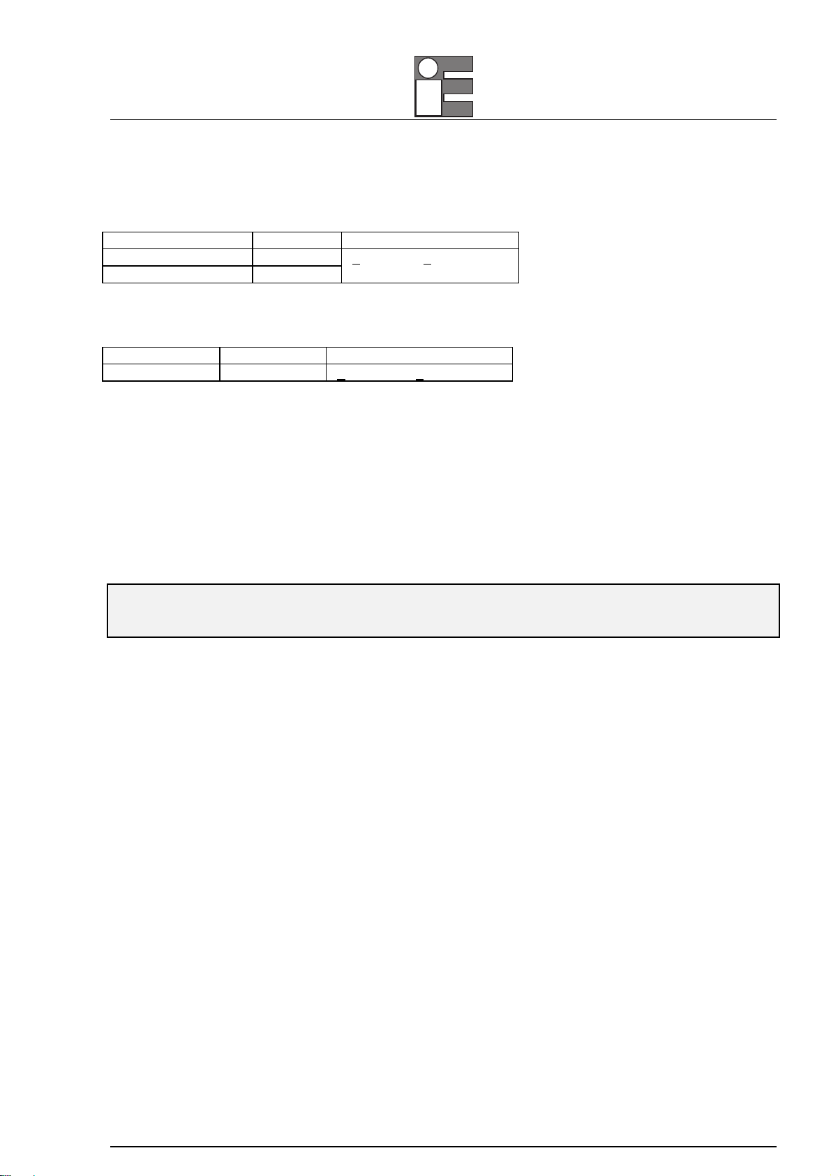
Duty Cycle
Range Resolution Accuracy
0.1%~99.9% 0.1% +1.2% of rdg + 2 dgts
Pulse width: >100us, <100ms;
Frequency width: 5Hz – 150kHz
Sensitivity: >0.5V RMS
MM850592 ed. 01 - Mini MMX II
7
Overload protection: 600V dc or ac rms.
Temperature
Range Resolution Accuracy
-20°C~+760°C 1°C
-4°F~+1400°F 1°F
+3% of rdg +5°C/9°F
Sensor: Type K Thermocouple
Overload protection: 600V dc or ac rms..
Diode Test
Test current Resolution Accuracy
0.3mA typical 1 mV +10% of rdg + 5 dgts
Open circuit voltage: 1.5V dc typical
Overload protection: 600V dc or ac rms.
Audible continuity
Audible threshold: Less than150Ω; Test current: <0.3mA
Overload protection: 600V dc or ac rms.
OPERATION
WARNING
RISK OF ELECTROCUTION.HIGH-VOLTAGE CIRCUITS,BOTH AC AND DC, ARE VERY DANGEROUS AND SHOULD BE
MEASURED WITH GREAT CARE.
1. ALWAYS turn the function switch to the OFF position when the meter is not in use. This meter has
Auto OFF that automatically shuts the meter OFF if 15 minutes elapse between uses.
2. If “OL” appears in the display during a measurement, the value exceeds the range you have selected.
Change to a higher range.
NOTE: ON SOME LOW AC AND DC VOLTAGE RANGES,WITH THE TEST LEADS NOT CONNECTED TO A DEVICE,THE
DISPLAY MAY SHOW A RANDOM,CHANGING READING.THIS IS NORMAL AND IS CAUSED BY THE HIGH-INPUT
SENSITIVITY.THE READING WILL STABILIZE AND GIVE A PROPER MEASUREMENT WHEN CONNECTED TO A CIRCUIT.
MODE BUTTON
To select Diode/Continuity or DC/AC current
RANGE BUTTON
When the meter is first turned on, it automatically goes into AutoRanging. This automatically selects the
best range for the measurements being made and is generally the best mode for most measurements. For
measurement situations requiring that a range be manually selected, perform the following:
1. Press the RANGE button. The “AUTO” display indicator will turn off.
2. Press the RANGE button to step through the available ranges until you select the range you want.
3. Press and hold the RANGE button for 2 seconds to exit the ManualRanging mode and return to
AutoRanging. (If backlight is turn on, please press BACKLIGHT button it will turn off)

MM850592 ed. 01 - Mini MMX II
8
DATA HOLD BUTTON
The Data Hold function allows the meter to "freeze" a measurement for later reference.
1. Press the DATA HOLD button to “freeze” the reading on the indicator. The indicator “HOLD” will be
appear in the display.
2. Press the DATA HOLD button to return to normal operation.
RELATIVE BUTTON
The relative measurement feature allows you to make measurements relative to a stored reference value. A
reference voltage, current, etc. can be stored and measurements made in comparison to that value. The
displayed value is the difference between the reference value and the measured value.
1. Perform any measurement as described in the operating instructions.
2. Press the RELATIVE button to store the reading in the display and the "REL" indicator will appear on
the display.
3. The display will now indicate the difference between the stored value and the measured value.
4. Press the RELATIVE button to return to normal operation.
BACKLIGHT BUTTON
1. Press the BACKLIGHT button 2 seconds the display light ON
2. Press BACKLIGHT button again to exit the light mode.
Hz/%duty BUTTON
Press Hz/Duty Button to choose Frequency or Duty Cycle in the range of Frequency; Press Hz/%Duty
Button to measure Frequency or Duty Cycle while measures voltage or Current, the Voltage/Current
requirement and range of Frequency see the following form, press Hz/%Duty Button to return to
measurement of Voltage or Current.
Range
(DC/AC )
Sensitivity Frequency
width
4V ≥2V rms 5Hz~10kHz
≥15V rms 5Hz~20kHz40V, 400V
≥25V rms 5Hz~100kHz
1000V/1000V ≥450V rms 50Hz~1kHz
400mA ≥5mA rms 5Hz~5kHz
10A ≥5A rms 5Hz~1kHz
Note: The above data only for reference.

MM850592 ed. 01 - Mini MMX II
9
DC VOLTAGE MEASUREMENTS
CAUTION
DO NOT MEASURE DC VOLTAGES IF A MOTOR ON THE CIRCUIT IS BEING SWITCHED ON OR OFF. LARGE VOLTAGE
SURGES MAY OCCUR THAT CAN DAMAGE THE METER.
1. Set the function switch to the V DC position (“mV” will appear in the display).
2. Insert the black test lead banana plug into the negative (COM) jack and the red test lead banana plug
into the positive (V) jack.
3. Touch the test probe tips to the circuit under test. Be sure to observe the correct polarity (red lead to
positive, black lead to negative).
4. Read the voltage in the display. The display will indicate the proper decimal point and value. If the
polarity is reversed, the display will show (-) minus before the value.
AC VOLTAGE MEASUREMENTS
WARNING
RISK OF ELECTROCUTION.THE PROBE TIPS MAY NOT BE LONG ENOUGH TO CONTACT THE LIVE PARTS INSIDE SOME
240V OUTLETS FOR APPLIANCES BECAUSE THE CONTACTS ARE RECESSED DEEP IN THE OUTLETS.AS A RESULT,THE
READING MAY SHOW 0VOLTS WHEN THE OUTLET ACTUALLY HAS VOLTAGE ON IT.MAKE SURE THE PROBE TIPS ARE
TOUCHING THE METAL CONTACTS INSIDE THE OUTLET BEFORE ASSUMING THAT NO VOLTAGE IS PRESENT.
CAUTION
DO NOT MEASURE AC VOLTAGES IF A MOTOR ON THE CIRCUIT IS BEING SWITCHED ON OR OFF. LARGE VOLTAGE
SURGES MAY OCCUR THAT CAN DAMAGE THE METER.
1. Set the function switch to the V AC position.
2. Insert the black test lead banana plug into the negative (COM) jack and the red test lead banana plug
into the positive (V) jack.
3. Touch the test probe tips to the circuit under test.
4. Read the voltage in the display. The display will indicate the proper decimal point, value and symbol
(AC, V, etc.).
DC CURRENT MEASUREMENTS
CAUTION
DO NOT MAKE CURRENT MEASUREMENTS ON THE 10A SCALE FOR LONGER THAN 30 SECONDS.EXCEEDING 30
SECONDS MAY CAUSE DAMAGE TO THE METER AND/OR THE TEST LEADS.
1. Insert the black test lead banana plug into the negative (COM) jack.
2. For current measurements up to 4000µA DC, set the function switch to the µA position and insert the
red test lead banana plug into the (µA) jack.
3. For current measurements up to 400mA DC, set the function switch to the mA range and insert the red
test lead banana plug into the (mA) jack.
4. For current measurements up to 10A DC, set the function switch to the A position and insert the red
test lead banana plug into the 10A jack.
5. Press the AC/DC button until “DC” appears in the display.
MM850592 ed. 01 - Mini MMX II
10
6. Remove power from the circuit under test, then open up the circuit at the point where you wish to
measure current.
7. Touch the black test probe tip to the negative side of the circuit. Touch the red test probe tip to the
positive side of the circuit.
8. Apply power to the circuit.
9. Read the current in the display. The display will indicate the proper decimal point, value and symbol.
AC CURRENT MEASUREMENTS
WARNING
TO AVOID ELECTRIC SHOCK,DO NOT MEASURE AC CURRENT ON ANY CIRCUIT WHOSE VOLTAGE EXCEEDS 250V AC.
CAUTION
DO NOT MAKE CURRENT MEASUREMENTS ON THE 10A SCALE FOR LONGER THAN 30 SECONDS.EXCEEDING 30
SECONDS MAY CAUSE DAMAGE TO THE METER AND/OR THE TEST LEADS.
1. Insert the black test lead banana plug into the negative (COM) jack.
2. For current measurements up to 4000µA AC, set the function switch to the µA position and insert the
red test lead banana plug into the (µA) jack.
3. For current measurements up to 400mA AC, set the function switch to the mA range and insert the red
test lead banana plug into the (mA) jack.
4. For current measurements up to 10A AC, set the function switch to the A position and insert the red
test lead banana plug into the 10A jack.
5. Press the AC/DC button until “AC” appears in the display.
6. Remove power from the circuit under test, then open up the circuit at the point where you wish to
measure current.
7. Touch the black test probe tip to the negative side of the circuit. And touch the red test probe tip to the
positive side of the circuit.
8. Apply power to the circuit.Read the current in the display. The display will indicate the proper decimal
point, value and symbol.
RESISTANCE MEASUREMENTS
WARNING
TO AVOID ELECTRIC SHOCK,DISCONNECT POWER TO THE UNIT UNDER TEST AND DISCHARGE ALL CAPACITORS
BEFORE TAKING ANY RESISTANCE MEASUREMENTS.REMOVE THE BATTERIES AND UNPLUG THE LINE CORDS.
1. Set the function switch to the Ω position.
2. Insert the black test lead banana plug into the negative (COM) jack and the red test lead banana plug
into the positive Ωjack.
3. Touch the test probe tips across the circuit or part under test. It is best to disconnect one side of the
part under test so the rest of the circuit will not interfere with the resistance reading.
4. Read the resistance in the display. The display will indicate the proper decimal point, value and symbol.

MM850592 ed. 01 - Mini MMX II
11
CONTINUITY CHECK
WARNING
TO AVOID ELECTRIC SHOCK,NEVER MEASURE CONTINUITY ON CIRCUITS OR WIRES THAT HAVE VOLTAGE ON THEM.
1. Set the function switch to the position.
2. Insert the black lead banana plug into the negative (-) jack (COM) and the red test lead banana plug
into the positive (+) jack (Ω).
3. Press the button until the symbol appears in the display.
4. Touch the test probe tips to the circuit or wire you wish to check.
5. If the resistance is less than approximately 150Ω, the audible signal will sound. The display will also
show the actual resistance.
DIODE TEST
WARNING
TO AVOID ELECTRIC SHOCK,DO NOT TEST ANY DIODE THAT HAS VOLTAGE ON IT.
1. Set the function switch to position.
2. Press the button until the symbol appears in the display.
3. Insert the black test lead banana plug into the negative (-) jack (COM) and the red test lead banana
plug into the positive (+) jack (Ω).
4. Touch the test probe tips to the diode or semiconductor junction you wish to test. Note the meter
reading
5. Reverse the probe polarity by switching probe position. Note this reading.
6. The diode or junction can be evaluated as follows:
A. If one reading shows a value and the other reading shows OL, the diode is good.
B. If both readings show OL, the device is open.
C. If both readings are very small or 0, the device is shorted.
NOTE: THE VALUE INDICATED IN THE DISPLAY DURING THE DIODE CHECK IS THE FORWARD VOLTAGE.
FREQUENCY MEASUREMENT
1. Set the function switch to the FREQ position.
2. Insert the black test lead banana plug into the negative (-) jack (COM) and the red test lead banana
plug into the positive (+) jack (F).
3. Touch the test probe tips to the circuit under test.
4. Read the frequency in the display. The digital reading will indicate the proper decimal point, symbols
(Hz, kHz) and value.

MM850592 ed. 01 - Mini MMX II
12
CAPACITANCE MEASUREMENTS
WARNING
TO AVOID ELECTRIC SHOCK,DISCONNECT POWER TO THE UNIT UNDER TEST AND DISCHARGE ALL CAPACITORS
BEFORE TAKING ANY CAPACITANCE MEASUREMENTS.REMOVE THE BATTERIES AND UNPLUG THE LINE CORDS.
1. Set the function switch to the CAP position. (“µF” and a small value will appear in the display).
2. Insert the black test lead banana plug into the negative (-) jack (COM) and the red test lead banana
plug into the positive (+) jack (CAP).
3. Touch the test leads to the capacitor to be tested. The display will indicate the proper decimal point,
value and symbol.
TEMPERATURE MEASUREMENTS
WARNING
TO AVOID ELECTRIC SHOCK,DISCONNECT BOTH TEST PROBES FROM ANY SOURCE OF VOLTAGE BEFORE MAKING A
TEMPERATURE MEASUREMENT.
1. If you wish to measure temperature in °F, set the function switch to the °F range. If you wish to
measure temperature in °C, set the function switch to the °C range.
2. Insert the Temperature Probe into the negative (-) jack (COM) and the positive (+) jack (Temperature),
making sure to observe the correct polarity.
3. Touch the Temperature Probe head to the part whose temperature you wish to measure. Keep the
probe touching the part under test until the reading stabilizes (about 30 seconds).
4. Read the temperature in the display. The digital reading will indicate the proper decimal point and
value.
WARNING
TO AVOID ELECTRIC SHOCK,BE SURE THE THERMOCOUPLE HAS BEEN REMOVED BEFORE CHANGING TO ANOTHER
MEASUREMENT FUNCTION.
REPLACING THE BATTERY
WARNING
TO AVOID ELECTRIC SHOCK,DISCONNECT THE TEST LEADS FROM ANY SOURCE OF VOLTAGE BEFORE REMOVING THE
BATTERY DOOR.
1. When the batteries become exhausted or drop below the operating voltage, “BAT” will appear in the
right-hand side of the LCD display. The battery should be replaced.
2. Follow instructions for installing battery. See the Battery Installation section of this manual.
3. Dispose of the old battery properly.
WARNING
TO AVOID ELECTRIC SHOCK,DO NOT OPERATE YOUR METER UNTIL THE BATTERY DOOR IS IN PLACE AND FASTENED
SECURELY.
MM850592 ed. 01 - Mini MMX II
13
BATTERY INSTALLATION
WARNING
TO AVOID ELECTRIC SHOCK,DISCONNECT THE TEST LEADS FROM ANY SOURCE OF VOLTAGE BEFORE REMOVING THE
BATTERY DOOR.
1. Disconnect the test leads from the meter.
2. Open the battery door by loosening the screw using a Phillips head screwdriver.
3. Insert the battery into battery holder, observing the correct polarity.
4. Put the battery door back in place. Secure with the two screws.
WARNING
TO AVOID ELECTRIC SHOCK,DO NOT OPERATE THE METER UNTIL THE BATTERY DOOR IS IN PLACE AND FASTENED
SECURELY.
NOTE: IF YOUR METER DOES NOT WORK PROPERLY,CHECK THE FUSES AND BATTERY TO MAKE SURE THAT THEY ARE
STILL GOOD AND THAT THEY ARE PROPERLY INSERTED.
REPLACING THE FUSES
WARNING
TO AVOID ELECTRIC SHOCK,DISCONNECT THE TEST LEADS FROM ANY SOURCE OF VOLTAGE BEFORE REMOVING THE
FUSE DOOR.
1. Disconnect the test leads from the meter and any item under test.
2. Open the fuse door by loosening the screw on the door using a Phillips head screwdriver.
3. Remove the old fuse from its holder by gently pulling it out.
4. Install the new fuse into the holder.
5. Always use a fuse of the proper size and value (0.5A/1000V fast blow for the 400mA range, 10A/1000V
fast blow for the 10A range).
6. Put the fuse door back in place. Insert the screw and tighten it securely.
WARNING
TO AVOID ELECTRIC SHOCK,DO NOT OPERATE YOUR METER UNTIL THE FUSE DOOR IS IN PLACE AND FASTENED
SECURELY.

MM850592 ed. 01 - Mini MMX II
14
Warranty terms
Eurotron Instruments warrants its products against defects in materials and workmanship for the period
declared from the date of the original retail purchase.
This warranty applies to the original purchaser only.
If the unit should malfunction, it must be returned during the warranty period, transportation prepaid, to
Eurotron for evaluation. Upon examination, if the unit is found to be defective it will be repaired or replaced
at no charge.
Direct all warranty and repair requests/inquiries to the Eurotron Customer Service Department. BEFORE
RETURNING ANY PRODUCT(S) TO EUROTRON, PURCHASER MUST OBTAIN AN AUTHORIZED
RETURN (AR) NUMBER FROM EUROTRON‘S CUSTOMER SERVICE DEPARTMENT (IN ORDER TO
AVOID PROCESSING DELAYS).
Please include a copy of the original invoice or a small service charge may be applied.
The purchaser is responsible for shipping charges, freight, insurance and proper packaging to prevent
breakage in transit.
Eurotron‘s WARRANTY does not apply to defects resulting from any action of the purchaser, including but
not limited to mishandling, improper interfacing, operation outside of design limits, improper repair, or
unauthorized modification. This WARRANTY is VOID if the unit shows evidence of having been tampered
with or shows evidence of being damaged as a result of excessive corrosion; or current, heat, moisture or
vibration; improper specification; misapplication; misuse or other operating conditions outside of Eurotron‘s
control.

MM850592 ed. 01 - Mini MMX II
15
NOTA INTRODUTTIVA
Scopo di questo manuale è quello di fornire le informazioni utili ad un corretto uso dello strumento.
Le informazioni contenute in questo manuale sono di esclusiva proprietà della Eurotron Instruments che
ne vieta l’utilizzo o la trasmissione in ogni forma anche parziale, in originale o in copia, per scopi diversi da
quello sopra indicato senza previa autorizzazione.
Eurotron Instruments ha dedicato la massima attenzione nella preparazione di questo manuale e ritiene
che le informazioni in esso contenute siano accurate. I prodotti Eurotron Instruments sono soggetti a
continua evoluzione al fine di proporre uno strumento tecnologicamente all’avanguardia; questi
aggiornamenti possono richiedere la modifica di questo documento. La Eurotron Instruments si riserva il
diritto di modificarne il contenuto in qualsiasi momento e senza darne specifica notizia.
Eventuali interventi di manutenzione straordinaria dovranno essere effettuati SOLO da personale qualificato.
La Eurotron Instruments fornirà, a richiesta, tutte le istruzioni e le procedure per interventi di riparazione e
taratura. Si raccomanda di contattare i nostri tecnici per qualsiasi esigenza di supporto.
Lo strumento è stato progettato in accordo alle direttive n°89/336/CEE sulla compatibilità elettromagnetica.
Eurotron Instruments non si assume alcuna responsabilità derivante da eventuali danni causati da un uso
improprio, da errori, omissioni o errata interpretazione delle informazioni contenute in questo manuale.
Tutti i diritti sono riservati
Copyright © 2006
Eurotron Instruments SpA
Viale F.lli Casiraghi 409/413
20099 Sesto S. Giovanni (MI)
Tel. : +39-02 24 88 201
FAX: +39-02 24 40 286
Mail: info@eurotron.com

MM850592 ed. 01 - Mini MMX II
16
INFORMAZIONI DI SICUREZZA
Osservare le seguenti informazioni sulla sicurezza per garantire la sicurezza personale dell'operatore con lo
strumento:
•Non usare lo strumento o i suoi terminali se sono danneggiati, o se vi è il sospetto che lo strumento
non lavori in modo corretto.
•Non mettersi mai collegati a terra quando si fanno misure elettriche. Non toccare parti metalliche
esposte, prese, cavi ecc. che potrebbero essere potenzialmente collegati a terra. Tenere il proprio
corpo isolato da terra utilizzando vestiti asciutti, scarpe in gomma, tappeti in gomma o qualsiasi altro
materiale che sia stato certificato come isolante.
•Togliere sempre alimentazione al circuito sotto misura prima di effettuare tagli, dissaldature o
interruzione di circuiti. Piccole quantità di corrente possono essere pericolose.
•Usare cautela quando si lavora con tensioni oltre i 60V CC o i 30 V CA RMS; tali tensioni possono
provocare scosse pericolose
•Tenere sempre le dita dietro la zona di sicurezza delle sonde quando si utilizzano con lo strumento.
•La misura di tensioni che superano i limiti dello strumento può danneggiare il multimetro ed esporre
l'operatore a scosse pericolose. Tenere sempre presente i limiti operativi del multimetro come indicato
sulla parte frontale dello strumento
•Non applicare mai tensioni o correnti che superano i livelli massimi indicati
SIMBOLI PER LA SICUREZZA
Questo simbolo, adiacente ad un altro simbolo, a un dispositivo o apparecchio in
funzione indica che l'operatore deve far riferimento alle spiegazioni presenti nel
manuale d'uso per evitare lesioni personali o il danneggiamento dello strumento.
Il simbolo WARNING indica una situazione potenzialmente a rischio, che se non
evitata può provocare la morte o serie lesioni personali.
Il simbolo CAUTION indica una situazione potenzialmente pericolosa, che se non
evitata può danneggiare lo strumento.
Questo simbolo avvisa l'operatore che il/i terminale/i così evidenziati possono non
essere collegati a punti del circuito in cui il voltaggio rispetto alla messa a terra
eccede (in questo caso) i 1000 V CA o CC.
Questo simbolo, adiacente ad uno o più apparecchi, li identifica come operativi a
range di lavoro che, nell'utilizzo normale, possono essere soggetti a tensioni
particolarmente pericolose. Per la massima sicurezza, lo strumento e i suoi contatti
non devono essere tenuti in tensioni insieme a questi apparecchi.
WARNING
CAUTION
MAX
500V

MM850592 ed. 01 - Mini MMX II
17
36
¡ã
9
10
8
4
10A
A
mA
V
Ω
¡ã¡ã
μ
¡ã
F
C
11
12
7
REL
1
2
AC
Hz%
DC
AUTO
Hz%
kM
F
C
5
CONTROLLI E PRESE
1. Ampio display LCD a 4000 conteggi provvisto di indicatori simbolici
2. Pulsante del campo di misura a pressione
3. Pulsante Frequenza/% Duty
4. Pulsante a pressione MODE.
5. Pulsante a pressione Data Hold
6. Pulsante a pressione Misura Relativa
7. Pulsante a pressione per la retroilluminazione
8. Interruttore funzioni
9. Connettore d'ingresso 10A (positivo)
10. Connettore d'ingresso µA/mA
11. Ingresso positivo per misure di Tensione CA/CC, Hz/ Ciclo Duty %, Ohm, Test Diodi, Continuità,
Capacità, Temperatura (°C o °F)
12. Connettore d'ingresso COM (negativo)
SINBOLI E SIGNIFICATO
Continuità
BAT Batteria scarica
Diodi
DATA HOLD Data Hold
AUTO Auto Range
AC Tensione o Corrente Alternata
DC Tensione o Corrente Continua
MM850592 ed. 01 - Mini MMX II
18
CARATTERISTICHE TECNICHE
Lo strumento è conforme alla norma: EN61010-1.
Isolamento: Classe 2, doppio isolamento
Categoria per sovratensioni: CATIII 1000V, CATIV600V.
Display: LCD a 4000 conteggi con indicatori delle funzioni
Polarità: Automatica, con indicazione della polarità negativa (-).
Overrange: indicazione tramite simbolo “OL”
Indicazione batteria scarica: Il simbolo "BAT" viene visualizzato quando la tensione della batteria scende
al di sotto del livello operativo.
Velocità di misurazione: 2 volte a secondo, nominale.
Auto spegnimento: lo strumento si spegne automaticamente dopo un periodo di circa 15 minuti di
inattività.
Condizioni ambientali operative: da 0°C a 50°C (da 32°F a 122°F) a < 70 % di umidità relativa.
Temperatura di stoccaggio: da -20°C a 60°C (da -4°F a 140°F) a < 80 % di umidità relativa.
Massima altezza per uso interno: 2000m
Grado di inquinamento: 2
Alimentazione: una batteria 9V , NEDA 1604, IEC 6F22.
Dimensioni: 182 (A) x 82 (L) x55 (P) mm
Peso: circa 375g.
L'accuratezza è dichiarata da 18°C a 28°C (da 65°F a 83°F), < 70 % di umidità relativa.
Tensione CC (Auto-range)
Range Risoluzione Accuratezza
400.0mV 0.1mV +0.5% val. mis. + 2 d
4.000V 1mV
40.00V 10mV
400.0V 100mV
+1.2% val. mis. + 2 d
1000V 1V +1.5% val. mis. + 2 d
Impedenza in ingresso: 7.8MΩ.
Massima tensione in ingresso: 1000V CC or 1000V CA RMS.
Tensione CA (Auto-range tranne che a 400mV)
Range Risoluzione Accuratezza
400.0mV 0.1mV +1.5% val. mis. + 70 d
4.000V 1mV +1.2% val. mis. + 3 d
40.00V 10mV
400.0V 100mV
+1.5% val. mis. + 3 d
1000V 1V +2.0% val. mis. + 4 d
Impedenza in ingresso: 7.8MΩ.
Risposta CA: da 50 Hz a 400 Hz
Massima tensione in ingresso: 1000V CC or 1000V CA RMS.
Corrente CC (Auto-range per µA e mA)
Range Risoluzione Accuratezza
400.0µA 0.1µA +1.0% val. mis. + 3 d
4000µA 1µA
40.00mA 10µA
400.0mA 100µA
+1.5% val. mis. + 3 d
10A 10mA +2.5% val. mis + 5 d
Protezione da sovraccarico: Fusibili da 0.5A / 1000V e da 10A / 1000V
Massima corrente in ingresso: 400mA CC o 400mA CC RMS su range µA / mA, 10A CC o CA RMS su
range da 10A.

MM850592 ed. 01 - Mini MMX II
19
Corrente CA (Auto-range per µA e mA)
Range Risoluzione Accuratezza
400.0µA 0.1µA +1.5% val. mis. + 5 d
4000µA 1µA
40.00mA 10µA
400.0mA 100µA
+1.8% val. mis. + 5 d
10A 10mA +3.0% val. mis. + 7 d
Protezione da sovraccarico: Fusibili da 0.5A / 1000V e da 10A / 1000V
Risposta CA: da 50 Hz a 400 Hz
Massima corrente in ingresso: 400mA CC o 400mA CC RMS su range µA / mA, 10A CC o CA RMS su
range da 10A.
Resistenza (Auto-range)
Range Risoluzione Accuratezza
400.0Ω0.1Ω+1.2% val. mis. 4 d
4.000kΩ1Ω+1.0% val. mis. + 2 d
40.00kΩ10Ω
400.0kΩ100Ω
4.000MΩ1kΩ
+1.2% val. mis. + 2 d
40.00MΩ10kΩ+2.0% val. mis. + 3 d
Protezione ingresso: 600V CD o 600V CA RMS.
Capacità (Auto-range)
Range Risoluzione Accuratezza
4.000µF 1pF +5.0% val. mis. +0.5µF
40.00µF 10pF +5.0% val. mis. + 7 d
400.0µF 0.1µF
4.000µF 1µF
40.00µF 10µF
+3.0% val. mis. + 5 d
200.0µF 0.1µF +5.0% val. mis. + 5 d
Protezione ingresso: 600V CD o 600V CA RMS.
Frequenza (Auto-range)
Range Risoluzione Accuratezza
9.999Hz 0.001Hz
99.99Hz 0.01Hz
+1.5% val. mis. + 5 d
999.9Hz 0.1Hz
9.999kHz 1Hz
99.99kHz 10Hz
999.9kHz 100Hz
+1.2% val. mis. + 3 d
9.999MHz 1kHz +1.5% val. mis. + 4 d
Sensibilità: >0.5V RMS mentre ≤1MHz ;
Sensibilità: >3V RMS mentre >1MHz ;
Protezione da sovraccarico: 600V CD o 600V CA RMS.
MM850592 ed. 01 - Mini MMX II
20
Duty Cycle
Range Risoluzione Accuratezza
0.1%~99.9% 0.1% +1.2% val. mis. + 2 d
Larghezza d'impulso: >100µs, <100ms;
Banda di frequenza: 5Hz – 150kHz
Sensibilità: >0.5V RMS
Protezione da sovraccarico: 600V CD o 600V CA RMS.
Temperatura
Range Risoluzione Accuratezza
-20°C~+760°C 1°C
-4°F~+1400°F 1°F
+3% val. mis. +5°C/9°F
Sensore: termocoppia di tipo K
Protezione da sovraccarico: 600V CD o 600V CA RMS.
Test per Diodi
Corrente di test Risoluzione Accuratezza
0.3mA tipico 1 mV +10% val.mis. + 5 d
Tensione circuito aperto: 1.5V CC tipico
Protezione da sovraccarico: 600V CD o 600V CA RMS.
Test di continuità
Livello di segnalazione: inferiore a 150Ω; Corrente di test: <0.3mA
Protezione da sovraccarico: 600V CD o 600V CA RMS.
Table of contents
Languages:


