Eusonar Praktik 6 Pro 2 User manual

1
Table of contents
INTRODUCTION...........................................................................................................................2
TECHNICAL SPECIFICATIONS OF THE SONAR ....................................................................4
FIRST AQUANTANCE WITH THE SONAR……………………………………………………4
Sensor-converter and battery compartment………………………………………………. ………5
Unit control…………………………………………………………………………………..……7
Sonar screen……………………………………………………………………………………….9
OPERATION ORDER OF SONAR……………………………………………………..………11
SONAR OPTION MENU………………………………………...……………………………...13
Information display modes……………………………………………………………………….14
FISH ID…………………………………………………………………………………..………14
Pro……………………………………………………………………………………..…………17
Flasher……………………………………………………………………………………..……..18
Depth gauge…………………………………………………………………………………..….19
Fleet water……………………………………………………………………………………..…20
Demo…………………………………………………………………………………………..…20
Info…………………………………………………………………………………………….....21
Ruling of a screen…………………………………………………………………………….…..22
ZOOM……………………………………………………………………………………………22
NOF…………………………………………………………………………………………...…24
ADJUSTEMENTS…………………………………………………………………………….....25
Near-bottom thickness…………………………………………………………………………...25
"WINTER/SUMMER" mode…………………………………………………………………….25
Dead end........................................................................................................................................26
Sound and fish identification.........................................................................................................27
GENERAL RECOMENDATIONS .............................................................................................27
COMMON TROUBLES AND REMEDIES ................................................................................32
WARRANTY ................................................................................................................................34
CONTACT OF SERVICE CENTRE............................................................................................35

2
INTRODUCTION
History of fishing amounts to thousands of years. However, in reality each time the
fisherman faces the same challenges: how to find the fish and make it grab the bait. The sonar
cannot make the fish grab the bite, but it is able to solve the problem of finding this fish. You will
never catch the fish there where there is not any –and the sonar of “Praktik” company will help
you make this fact true in the literate sense of this word.
Operating principle of the “Praktik” soner is based on emission of ultra-sonic waves by the
transducer-converter into the water and subsequently receipt of the echo pulses reflected from the
bottom or other objects. The probing beam represents the cone, the top of which is the sensor,
normally located just below the water surface, and the basement is the bottom. When the ultrasonic
wave encounters some obstacle on its way, its part is reflected and comes back to the transducer-
converter which now operates as a receiver and converts the reflected ultra-sound into an electric
signal.
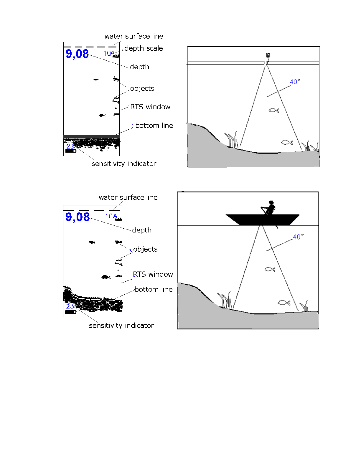
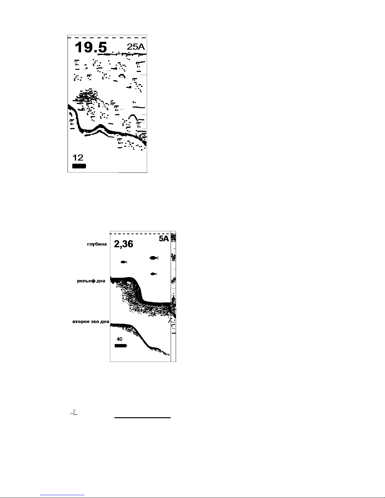
The microcomputer processes the electric signals and prints on the sonar screen the
information on the topography of the bottom and the objects caught in the beam zone. The figures
above show typical pictures on the sonar screen and related information regarding these pictures
in the water depth of the reservoir in winter and summer.
Probing pulsing into the water is performed with frequency adjusted from two to four times
a second. The screen pattern shifts with the same speed. Data from the current echo-pulse will
appear in the right part of the screen and then moves to the left. The display top corresponds to the
water surface, whereas the lower part –to the lower part of the selected depth range.
It is very important to understand that the sonar does not reflect volume (3D) representation
of the water depth but only longitudinal section passing through the middle of the probing cone.
That/s what creates an illusion that all the objects detected by the beam are located under the
sensor.
3
Display pattern in winter Winter reservoir
Display pattern in summer Summer reservoir
Sonar models ER-6 Pro2 can reflect as processed information in the format easy for understanding,
as well as unprocessed information (“raw”one which is more difficult for understanding but it is
more informative than in the first case) With the assistance of MENU one can choose the most
suitable type of information representation. If a fish gets in the probing cone of the display mode,
of the processed information, this event will be recorded and the fish outline will show up on the

4
display mode of the processed information. Near-bottom structures will look like spots on the
bottom contour. One can understand from the bottom line width if the bottom is dense or muddy,
and guess its structure.
TECHNICAL SPECIFICATION OF THE SONAR
FIRST AQUANTANCE WITH THE SONAR
Model ER-6 Pro2 sonar design is made in two units: electronic and sensor-converter unit
with the battery compartment. The sensor-converter is connected with the electronic unit with
assistance of the cable 2 m long.
Setting functions
Amplification, automatic or manual selection of the depth scale,
identification of the fish, “winter-summer” mode, adjusting
“zoom”, dead zone, “flasher” mode, fleet water.
Measuring depth range, m
0,5–25,0 m (measurement accuracy ±1sm for depth 0.5-10m
and ±10sm for depth from 10-25m )
Probing angle, degree
40°
Display
monochromic, high-contrast, frost-resistant,
resolution128×64 points (5×3sm)
Temperature range, °С
from –15 to +40°C
Power supply
1 element АА (200 operation hours with frequency 2 Hz)
Electronic block size
100×72×23
Sensor-converter size
25×80
Unit weight
170g

5
The electronic unit represents the structural design with two control buttons, transparent
window and tightly closed cable not less than two meters long. The level of leak resistance is
compliant with IP 67 standards.
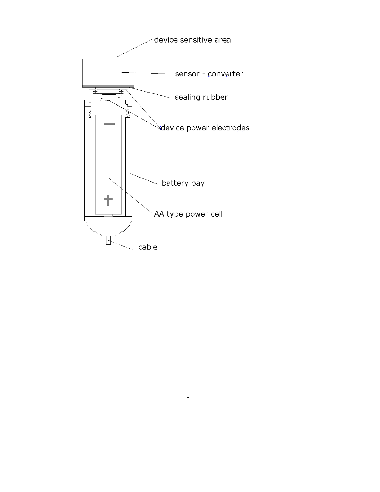
Sensor-converter and battery compartment
The sensor-converter works simultaneously as an acoustic wave emitter as a receiver
(microphone) of echo-signal objects reflected from the bottom. The sensor design is frost-
resistant, leak-proof (IP68). The sensor is screwed into the battery compartment. Pressurization of
the battery compartment is performed with assistance of the sealing silicone ring. When installing
the power supply unit АА it is necessary to observe polarity.
It is advisable to install he battery at home at a warm place. It will ensure avoidance of
appearance of the condensate water in the battery compartment. Take care of the sensor.
Unfortunately it does not float. It sinks and it is expensive. Besides, one should protect it from
severe blows over hard objects.
Under conditions of winter fishing it is desirable to lower the sensor below the underwater
ice edge to avoid appearance of false signals reflected from the vertical walls of the ice-hole.
To save the battery service life it is not recommended to leave the sensor-converter in frost:
when operating is must be wholly into the water, the temperature of which is always positive, and
when the sensor is not used –in a warm place under the clothes.
For correct depth measurement the sensible area of the sensor must be located strictly in
parallel to the water surface. It should be remembered that the bottom depth and other objects are
measured not relatively the water surface but to the sensor, that is why at its big depth the figures
shown by the sonar can differ considerably from the true ones.
The sonar is equipped with the special cable with the cover made of silicone resin,
connecting the electronic unit and the battery compartment with the sensor. This cable will remain
elastic even in the most severe frosts, with which an ordinary rubber cable will lose its elasticity
and can easily crack, thus losing its impermeability.
6
In the body of the device there are four fastening openings located along the body angles.
They are designated for fastening the cord and for installation the special furniture on the device
to fasten the sonar to the leg or the sleeve. The furniture is not included in the set.
There is a special bracket for the sensor in the delivery set. Its fastening to the boat is
performed with assistance of the clamp or other accessories. The sensor can be fastened on the
float as well. Fastening of the electric unit to the boat is possible with special holders for mobile
telephones.
Examples of uncomplicated appliances and furniture for the sonar fastening to the floating
craft are shown on our site www.rusonar.ru.

7
Unit control
There are two buttons to control the sonar. There functions are described below.
LEFT BUTTON
In operation mode
1. Switching between automatic and manual scale selection modes and “zoom” mode).
2. Illumination on/off (hold down for 5 sec)
In MENU mode:
Current MENU point value correction
Left button in operation mode serves to change over the sonar to one of three operation
modes: automatic scale selection (Auto Range), manual scale selection and “zoom” mode. If
automatic mode is chosen the current scale and “A” letter are reflected in the top right angle, and
if manual one–scale and “M” letter. In “zoom” mode scale is not reflected, instead the magnifier
with the figure mark will be output. If sensibility adjustment is performed it is possible to change
adjustment direction (increase or decrease) with the left button (single push).
If you hold the left button pushed long enough (around 5 sec) the screen illumination will be
switched on or off.
When the sonar is in MENU, the left button corrects MENU current point value.

8
RIGHT BUTTON
In operation mode
1. Sonar switch-off (single push)
2. Change-over to MENU (double push)
3. Durable push to adjust sensibility
In MENU mode:
Change-over between MENU points and exit to operation mode
Right button serves to switch on and off the sonar and also to exit MENU and changeover
between its points. The sonar switch-off is performed via single pushing, with this the countdown
figures will appear on the display: 3–2–1. If you push the right button once again during the
countdown, the sonar will change over to MENU mode. To adjust the sonar sensibility in the
operation mode it is necessary to hold the right button pushed, with this the vertical strip
“thermometer” will appear in the left side of the indicator that show change of sensibility. To
change the adjustment direction it is necessary to hold temporarily the left button.
After change over to MENU the right button goes through various MENU items. The sonar
will come back to the operation mode after finishing searching all items.
9
1
1
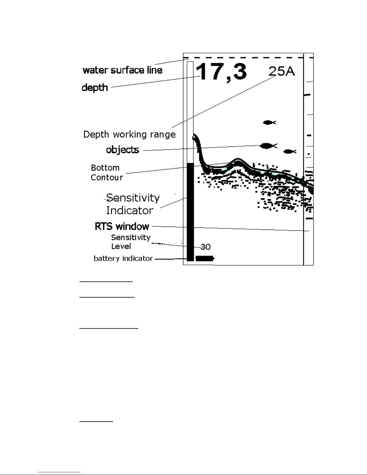
Sonar display
Water surface line is shown in the form of the running dotted line.
Digital depth value is updated two-four times a second with resolution ±1sm for depths to
10m and resolution ±10sm for depths from 10 to 25 meters.
Sensitivity indicator visual displays if the right button is pushed and held. Vertical strip
“thermometer” shows sensitivity rude value, and the figure under the depth value shows the exact
sensitivity value. Sensitivity indicator disappears from the screen when releasing the right button.
Sensitivity can be adjusted within the range from 0 to 28 units. Value 12 units is set automatically.
Adjustment direction (increase of decrease) can be changed if you push the left button for the short
moment during adjustment..
Soil density conventionally shows power of the echo-signal reflected from the bottom and
can vary from 0 to 20 units. The higher is the number, the more powerful the signal from the

10
bottom (or the high density of the soil), and vice versa, a small number will say that from the
bottom signal is weak (low soil density). With the same reflecting capacity of the bottom, the
density will be reduced with respect to the depth increase because with this the signal becomes
weaker.
Operation range shows what maximum depth can be reflected on the screen at a particular
moment. If there is letter A at the figure, it means that the device is in automatic scale selection
mode and it will be automatically changed when leaving beyond definite limits of the bottom
depth. If there is letter M, it means that the unit operates in the manual scale selection mode: it will
not change even if the bottom approaches considerably to the upper part of the screen or goes
beyond its lower limit. Scale value for this mode is set via MENU. At last, the magnifier symbol
with the figure instead of the operation range indicator informs that the sonar is in mode “zoom”
(it will be described separately).
RTS-window –this is the screen area which reflects all registered echo-signals from the
bottom and other objects without any processing. In the main area of the screen the data processed
by the computer
(bottom line, near-bottom structures and fish symbols) is displayed.
Battery indicator shows the capacity of battery at the given time. It has 12 gradations. If
the last level occurs, the device can operate for several hours, but when restarting the message
“Battery is low” can appear on the display. More accurate battery status can be assessed if you go
to the Info mode, where the battery voltage is specified in volts. The limit value of the battery
voltage at which the sonar can work effectively is 0.85W.
OPERATION ORDER OF SONAR
Total operation order:
1. Turn off (counter clockwise) the sensor from the battery compartment. Insert a new battery
into the battery compartment observing polarity (“plus” must be at the bottom). Put the sensor in

11
its place revolving clockwise. It is enough to turn the sensor tight manually for pressurization. Do
not use with this the tool type of pliers.
2. Press the right button. The message greeting will appear of the screen:
“Praktik ER-6 Pro2 Lucky fishing”,
which further on will be moved to the left on the screen.
ATTENTION!
If the sensor is not screwed tightly enough in the battery compartment, then the on the
display will appear a warning message “SENSOR?”. The same message will appear if a
cable is damaged.
After installing the batteries, it is recommended that you restart the device, so it will return
to the factory settings. Press and hold the left button and then press the right button for 1-
2 seconds. The message “OK” will appear on the display, and the following factory
settings will be installed:
–scaling: image auto-scaling mode;
–amplification: 12 (from 28 units);
–screen scale for its manual selection mode: 7 meters;
–screen view: fish definition mode and window RTS;
–fish identification and sound: are on;
–near bottom layer depth in “zoom” mode: 2 meters
- dead zone: 05-1 meter
“Winter/Summer” mode: summer
Resetting can be made in the different time, but only when the device is turned off.
Note: if battery was inserted earlier, then it is necessary to press the right button once to turn on
the sonar. All previously installed modes by doing so are saved.
3. Put the sensor into the water with assistance of the cable. It is desirable to put the sensor
fully below the ice edge in winter to avoid extreme cooling of the battery and offset of noise signal

12
of the ice-hole. After the sensor contacts the water the appearance of micro-bubbles on its sensible
surface is possible which can strongly dissipate registering signals and thus reduce sensibility and
mispresent the true picture. It is required to remove the bubbles plunging the sensor for several
times or rub the sensor surface with your fingers after plunging it into the water.
4. If the sensor is immobile the bottom on the screen will be imaged in the shape of even
line. With small depth and the bottom with good reflecting capacity in consequence of the multiple
re-reflecting signal from the bottom and the water surface appearance of several “bottom” lines
parallel to the true bottom and laying on the depths divisible by the true bottom depth is possible.
If the fish is caught in the beam cone the sound signal will go off, and the fish sign on the
corresponding depth will appear.
5. If the sensor is fixed on the moving boat, then the configuration of the bottom and the
near-bottom structures under the boat will be picked in. if the fish swims through the beam cone
the signal will ring out and the mark on the relative depth on the screen will appear.
6. To switch off the device it is necessary to press the right button one-time. Upon completion
of the countdown the sonar will be switched off.
7. If the sonar is in operation mode for more than four hours and none of the buttons is not
pushed for this time the sonar will be switched off automatically.
8. For durable switch off of the sonar it is recommended to de-energize it fully removing the
battery because it consumes energy even if it is switched off. Power consumption is miserable,
but low-quality batteries with this discharging current may increase in size and may damage the
battery compartment.
ATTENTION! Don’t leave the battery for the long period of time (inter-season) in the
battery compartment.

13
SONAR OPTION MENU
MENU serves to control operation modes and fine adjustment of the sonar. Input from the
operation mode is performed by double pushing the right button. The basic MENU consists of four
points. Designation of these MENU points if highlighted below.
MODES
SCALE OF DEPTH
NOISE AND OBJECT FILTER
SETTINGS
Immediately after MENU input the first MENU point will arrive on the screen–“MODES”.
To change over to the next point the right button should be pushed again. MENU exit to the
operation mode is performed by consequent pushing the right button till MENU points finish, after
that the operation mode screen will appear again.
After selecting necessary MENU point one can change its value by pushing the left button.
When necessary value is set you can change over to the next MENU point with assistance of the
left button and finally enter the operation mode again.
If the sonar is in MENU but the buttons have not been pushed for 15sec the device will
automatically change over to the operation mode.
14
MODES
This MENU point enables to select the most favorable mode of data representation on the screen.
FISH ID or processed data
Pro or professional mode
Flasher
Depth gauge
Fleet water mode for fleet water
Demo mode for operation in the air
Info device information
FISH ID mode
Display mode FISH ID is set immediately after changing the battery (per default).
The screen is divided in two unequal parts by the vertical strip in this mode. The window occupies
the principle area where processed data is displayed: bottom line, near bottom (at a distance from
the bottom not more than 1m) and “after bottom” structures, as well as the fish signs detected by
the sonar. It should be noted that not every object is regarded as the fish but the one that satisfies
definite criteria, wherefore the sonar may “not detect” the real
fish or, vice versa may take for it other object. The mechanism
of fish identification input in Praktik sonar is based on
measurement of nature of motion of the object caught in the
beam. If the nature of motion of this object satisfies the
identification criteria (set in the chip memory) then the fish
contour will appear on the screen.
The narrow window of the real signal will be displayed
in the right part of the screen (RTS). The sonar displays all the

15
data received in this window without any processing (so called “raw” data). It is more complicated
for perception than the fish signs, however it provides more additional data for an experienced
user.
In RTS window one can take notice of the echo-signals located in the beam zone. For
example, vertically falling load (feedbox) will be clearly seen in RTS, but it will not be detected
as the fish and we will not see the fish contour on the screen.
In FISH ID mode the bottom will be displayed in the form of the long dark strip, and in
respect of its thickness one can judge the bottom nature.
The light strip in one pixel will be present in the neat bottom line. It is this very strip that
shows the place from where the measurement and calculation of the depth value is performed.
Everything that is located above this strip will be referred to the near bottom structures. Soil density
provides additional data displayed under the depth figures. For instance, figures 1-5 is typical of
the muddy bottom, and 15-20 –for the hard bottom. To be precise, this value does not characterize
the bottom density as such but the strength of the signal reflected from it: the bigger they are, the
better the bottom reflects the signal and the smaller the depth is (because with the distance increase
the signal weakens).
For correct definition of the fish the properly set sensibility level has a significant
importance. With exaggerated sensibility level (especially in summer on a moving boat) when the
sonar can register even the weedy water, thermo-cline or suspended particles, it is quite possible
that these irregularities can appear on the screen in the form of the fish symbols. Stakes of tiny fish
can also cause appearance of big fish contours in the screen. Reducing of sensitivity will enable
to filter out these “disturbing” factor. It is impossible to provide specific recommendations
regarding setting the sensitivity level as condition at the reservoirs differ considerably.
In Praktik sonar, in FISH ID mode, fish of three sizes can be displayed. In the process of
the unit development and identification algorithms adjustment we used the fish of the following
sizes: carp 150g - for small fish contour, 500-700g- for average contour and carp for 1kg for big

16
fish contour. It is known that the sonar can see the fish first of all because of its air-bladder. That
is why its size will affect the fish contour size in the first run. For the same reason in summer
when moving the bubbles with gases on the algae may “appear” on the sonar screen as the fish.
Some clarifications regarding the place of the fish contour on the screen.
The fish requires ones of seconds to detect the fish as the object. As a rule, the fish contours
appearing near RTS 9 window (in the right part of the screen) they are the fish in the cone zone at
the moment. Further on these contours move from the left to the right on the screen. Naturally, this
movement does not correspond to real movement of the fish in the reservoir. The sonar makes
probing sending of acoustic signals 4 times a second. In conformity with this frequency the picture
on the screen moves. For example, if the fish contour is in the middle of the screen it means that
the fish was in the beam 10 sec ago, and if the fish contour is in the left part of the screen, the fish
was under the sensor 20 sec ago.
FISH ID mode or processed information output is designated firstly for not very experienced
users: professional would prefer other sensor modes, as raw data provide more data for reasoning
and enable to assess the condition of the reservoir with more accuracy. One should remember that
any fish-searching sonar for amateur and sport fishing is unable to define the specific size, weight
and view of the reflecting fish all by itself. Moreover, only very complicated and expensive models
that look more like military-oriented hydro-acoustic stations than the fish-searching sonar, are
able, and not in all the cases, to identify reliably the fish and cut out other objects. That is why one
should not expect from the device impossible: the screen displays only data processed in this or
that way coming from the sensor, but to understand in reality what is happening in the reservoir
can only the fisherman himself.
Pro mode (professional mode)
17
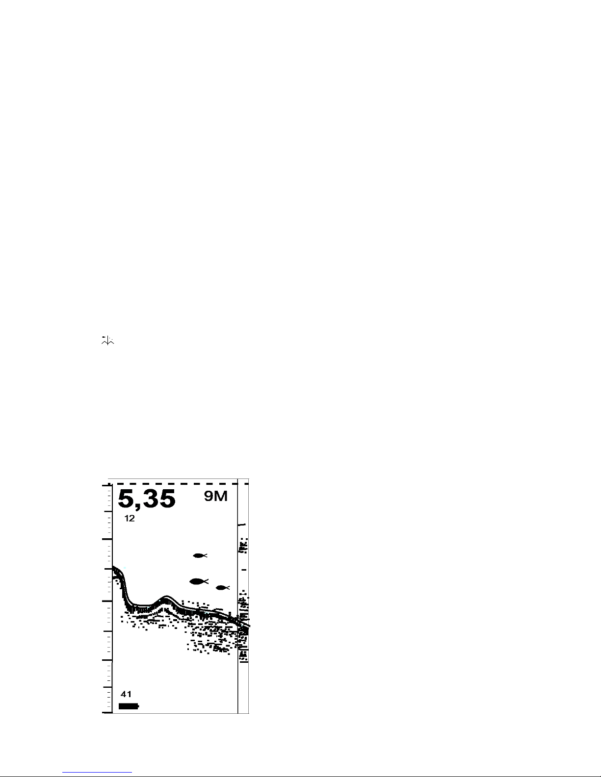
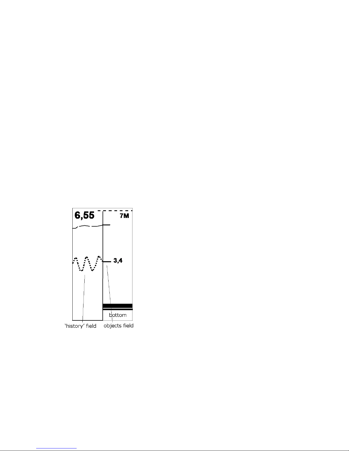
In mode Pro or reflecting raw data (without processing) the
whole screen is devoted for reflection of unprocessed data. The
sonar does not attempt to identify the fish, and it only shows all
reflected signals that it was able to detect. This mode is the most
useful for experienced fishermen as it allows to detect thermo-
clines, algae and other objects and better understanding of the water
thickness structure.
The picture on the display will depend on the preset
sensibility level. In sonar models ER-6 PRO2 adjustment is flexible,
that is why it is always possible to select optimal sensitivity level for the specific place at the
reservoir.
It is possible to survey data lying “beneath” the bottom. For example, in the small depth and
maximum sensibility not only the “second” bottom (as it
is shown on the picture), but the third bottom may appear
as well. The picture of that kind appears when the signal
is reflected several times from the bottom and the water
surface (so called signal over reflection). “Lying below”
data can provide an experienced user with additional data
on the nature of the reservoir. It is necessary to change
over the sonar to the manual scale selection mode so that
to see it (see the next unit), setting the scale exceeding the
bottom depth more than twice. Scale 5Аwith the bottom length 2,36m is chosen on the given
picture.
“Flasher” mode
In the operation modes described above the picture on the sonar screen is already the history
of what has been under the sensor several (or dozens) seconds ago. There is “Flasher” mode in
18
the sonar Praktik ER-6Pro2 to watch the objects in the real time scale mode. The screen is divided
in two equal parts in the “Flasher” mode. “History window”is on the left where unprocessed
signals that have been surveyed by the sonar are reflected (as in “Pro” mode). The Flasher
occupies the right half: with each update of the screen (4 times a second), it draws wide marks of
all detected objects including the bottom (it, different from other objects, will occupy the whole
width of the right part of the screen, and not the quarter of the width). Near the mark of the largest
detected object its depth is reflected. On the given picture it is shown how the balance beam
position in depth 3,4m at the moment has been changing.
Digitization of the largest object is performed not in all the depth but starting only from 1,5m
from the surface. This measure is taken for reducing the impact of the near-surface signals.
Owing to big depth the signal marks are more noticeable than ordinary echo-signals in Pro
modes, and over frequency of the measurements allow to display data in the real time scale mode.
At small depths ( 2-3m) this mode will not be that
efficient, whereas operation at big depths allows to survey real
bait movement pictures and, which is the most important, the fish
reaction to these activities. For delicate operation adjustment of
this mode it is recommended to select sensitivity. For this
purpose, it is recommended to sink the balance beam into the
water floor or closed to the bottom and to select sensitivity so that
your fishing gear could be clearly seen on the screen.
“Flasher” mode is recommended for winter fishing as there
will be more obstructing factors in summer when operating from the boat.
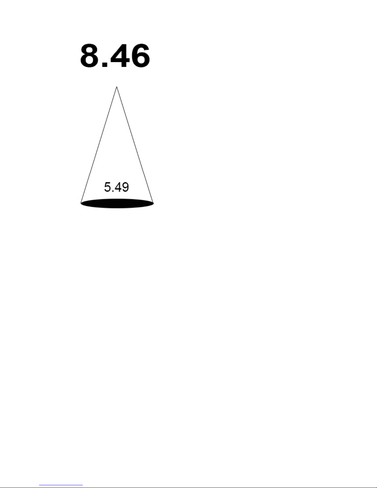
Depth gauge mode
Depth gauge mode is designated not only for accurate depth measurement, but also for beam
spot diameter display of sonar (sonar “print”). For the depth measurement in this mode the signals
19
probing and processing considerably differ from the
depth measurement in other sonar modes. Depth
measurement for the difficult condition is performed
especially precisely, for example, fleet water and
grown-over reservoirs may be referred to these
conditions. None of the fish and any other date on the
water depth is displayed.
Any activities and adjustments on the part of the
user are not required for operation in this mode.
Sensibility selection as performed automatically
depending on the reservoir conditions. The dead end is
always adjusted as 50 centimeters.
Diameter of the sonar spot at the bottom is measured in meters at the bottom of the cone
base. In the algorithm of calculation of the spot the data is involved, taking into account the
attenuation of the acoustic wave in the water, as well as numerous experimental data for sonar
“Praktik”. In reality in the water the beam cone has the shape of the inverted flame of a candle,
rather than the usual cone with the angle of 40 degrees. It is necessary to clarify that such
geometrical parameters of the sonar beam were defined by us specifically for practical
applications, since in such beam focuses the maximum density of acoustic power, and the angler
can clearly watch his bait (fishing tackle, plug, lure, etc.) on the screen.
ATTENTION! The Depth gauge mode works correctly with inactive sensor/ otherwise the
depth measurements will be unstable.
Depth gauge mode is recommended in cases when in other modes of the sonar the depth
reading is not stable on account of condition at the reservoir or confident depth definition with
large numbers indication is required.
Fleet water mode

20
Fleet water mode is intended for use in shallow water (2 meters or less). In this mode the
sonar provides the sounding of water by acoustic signals of very low power. It allows avoiding re-
reflected signals and receiving more reliable and understandable information on the display. The
sensitivity adjustment (with the right button) will also operate. At a depth of 2 meters the device
can measure the depth, but the high sensitivity cannot be achieved.
ATTENTION! In the fleet water mode the fish identification does not work (the contours
of the fish are not drawn when it appears in the beam zone). The sonar operates as in the Pro
mode, that means the display shows unprocessed information. On default in the fleet water mode
the dead end is adjusted as 50 cm.
DEMO mode
In the DEMO mode it is possible to check operating capacity of the sonar in the open air.
For this it is necessary to turn on the sonar, once more press the right button (exit to the MENU)
and with the left button choose the DEMO mode. Then to press the right button 4 times to scroll
through the settings and to exit to the standard operating mode. Further on it is required to hold
the sensor cable at a distance of 0,5-1,0m from the hard surface, e.g. from the floor. When the
sensor stops rolling the even strip of “the bottom”will be drawn and precise distance from the
floor in centimeters will be shown on the indicator. With slow lowering or lifting of the sensor
“the depth” will change.
Working capacity in the open air is recommended to perform with maximum sensitivity,
although with good reflection average one is enough. In DEMO mode the fish identification
mechanism does not work as the beam in the air is very narrow (about 5degree), and it is difficult
to register the signal reflected from the floor with this beam geometry, to say nothing of registration
of the echo-signals from other objects.
The device is considered to be in working capacity if by the method described above it will
be possible to register surely the distance between the sensor and the floor 1m or more. If down to
one meter the depth is not registered (zeros on the screen) the device has weak capacity (problems
Table of contents


