Mariner Mercury 225 Reference manual

94-11 1294Printed in U.S.A. - 1 -
No. 94-11
Powerhead Water Ingestion - 225 Model
Mariner and Mercury
1994 and 1995
225 hp Models
S/N 0D280813 thru 0G178947
Therehavebeensomereportsofwateringestioninto
the lower cylinders on these engines.
Water may enter the lower cylinders from the cooling
slots on the exhaust adapter plate. Water can cause
spark plug misfire, internal rust and possibly power-
head damage. Modifications to the exhaust adapter
plateareto bemadeto avoidwateringestion through
the exhaust ports.
Water may also accumulate in the lower cowl from
leaking hoses or from external spray. Accumulated
water can cause electrical problems and can be
drawn into the lower carburetors to cause spark plug
misfire, internal rust and possibly powerhead dam-
age.Hoseleaksaretoberepaired.Additionalcowlair
inletholes, toreduceunder-cowl vacuum,and longer
water drain check valves are to be added/installed to
help drain the lower cowl.
DEALER OUTBOARD INVENTORY:
Outboards within this serial number range must be
modified before use or retail sale.
Someoutboardswithinthisserialnumberrangewere
modified at the factory. Factory modifications and
some early field modifications have the new exhaust
adaptor plate p/n 818450A-1 installed. The new
adaptor plate is identified with a raised boss above
the poppet valve opening and p/n 818450C-2 is cast
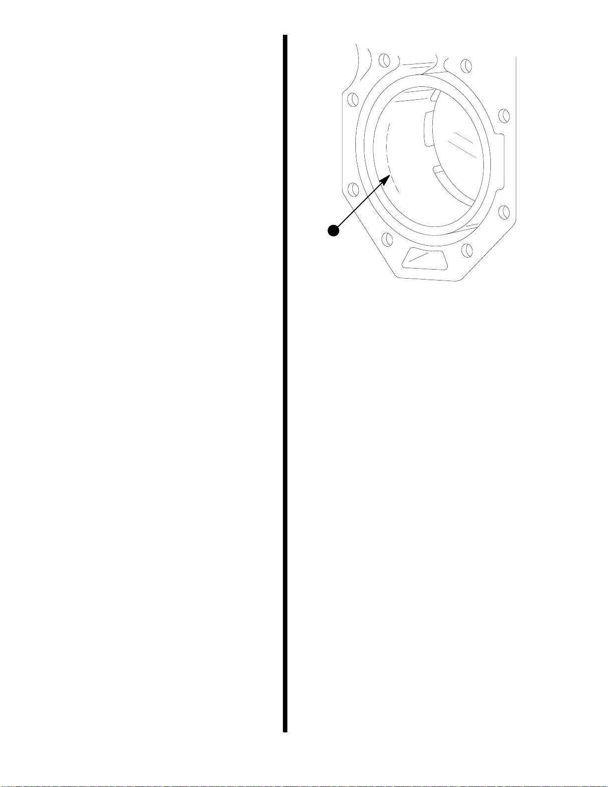
in the front of the plate as shown in figure 1.
28298
a
b
a - Casting Number 818450C-2
b - Raised Boss
Figure 1. New Exhaust Adaptor Plate.
Outboardsmodifiedat thefactoryalsohave aorange
dot on the outside of the shipping carton next to the
serialnumber. Outboardswiththisnewadaptorplate
haveallmodifications requiredbythisbulletin andre-
quire no further action.
OWNER NOTIFICATION (US AND CANADA):
A combination letter/claim will be sent to registered
owners of outboards within this serial number range.
The letter will advise the owner to return their out-
board to the selling dealer or authorized dealer for
warranty modifications. A copy of the letter is at-
tached to this service bulletin.
provided by http://www.crowleymarine.com

94-11 1294 - 2 -
REQUIRED TOOLS AND PARTS:
Order (1) p/n 828809A-1 Drill Fixture Kit (with drills)
- no charge.
Order (1) p/n 19-828808A-1 Repair Kit for each used
outboard.
Order (1) p/n 19-828808A-2 Repair Kit for each new
outboard.
Rust-oleum 7785 Cold Galvanizing Compound -
purchase locally.
Quicksilver Leveler p/n 92-75996.
Quicksilver Silicone Dielectric Grease
92-823506--1
MODIFICATIONS:
S/N 0D280813 thru 0G178947
CYLINDER BORE INSPECTION
Inspect cylinders for corrosion if the engine has been
operated. Disregard this section if the engine has not
been operated.
1. Remove both cylinder heads.
2. Clean bores with Quicksilver Paint Leveler p/n
92-75996.
3. Inspectcylinderboresforcrosshatchpattern,pit-
ting and wear. Figure 2 shows piston ring travel
limit.
Acceptable:
•Corrosion/discoloration above ring travel area
•Non-Uniform honing cross hatch
•Minor scratches
Unacceptable:
•Heavy corrosion or pitting in ring travel area.
•Honing cross hatch worn away.
•Scored Cylinder - deep vertical marks.
53659
a
a - Limit of Ring Travel.
Figure 2. Cylinder Inspection.
4. For help or authorization to replace the power-
head if the bore(s) is not acceptable:
US- CallOutboard Service(414) 929-5884or Quick-
Fax (800) 842-4550.
CANADA - Call Mercury Marine Service/Warranty
(905) 270-4481 or Quick Fax (800) 663-8334.
INTERNATIONAL - Call your area office.
5. If the cylinders are acceptable, oil all cylinder
bores and rotate crankshaft.
6. Reassemblecylinder headswith newo-ringsand
seals. Oil and install cylinder head bolts. Torque
boltsholding thermostathousingto 30lb. ft.(40.7
Nm)androtateanadditional90°. Torqueallother
cylinder head bolts to 20 lb. ft. (27.1 Nm) and ro-
tate an additional 90°as outlined in Service
Manual 90-822900 page 4A-36.
provided by http://www.crowleymarine.com

94-11 1294
- 3 -
S/N 0D280813 thru 0G178947
MODIFY EXHAUST ADAPTER PLATE
1. Remove powerhead per Service Manual
90-822900 page 4A-7 thru 4A-10.
2. Clean gasket material from powerhead base
flange and exhaust adapter plate surface.
3. Clean any corrosion from the powerhead base
flange using a small diameter wire wheel on an
electric or air tool. Use care not to damage or
round-off the gasket surfaces.
4. Paintthepowerheadbaseflangewithcold-galva-
nizing or zinc-rich paint, such as Rust-oleum
ZINC-SELE7785topreventcorrosion. Applytwo
light , uniform coats and allow to dry 30 minutes
for each coat. Outboards after s/n 0G178948
have a protective coating on the gasket surface.
5. Assemble drill fixture 828809 to the exhaust
adapter plate and drill four holes per figure 3.
53660
a
ab
a - 3/16 inch (4.8 mm) Diameter Holes 1/8 inch
(3.2 mm) Deep.
b - #39 Drill (2.6 mm) Hole Completely Through Casting
Section.
Figure 3. Drilling Fixture.
6. Install two p/n 19-828808 plugs into the exhaust
adapter plate as shown in figure 4. The top of the
plugs must be flush with the gasket surface. It is
notnecessarytoLoctiteorsealtheplugsinplace.
53661
a
a - Plugs (2).
Figure 4. Plug installation.
7. Assemblenewbase gasketwiththesealing bead
up and reassemble the powerhead. Torque the
10 powerhead nuts to 50 lb-ft (67.8 N.m) in 3 pro-
gressive steps as per the Service Manual
90-822900 page 4A-43. DO NOT use the “feel”
method. Non uniform torque can result in a
crushed gasket, water leaks or broken bolt(s) lat-
er in service.
8. Secure the thermostat bypass hoses to the ex-
haust adapter plate fittings with p/n
54-815504206 stainless steel hose clamps.
S/N 0D280813 thru 0G147353
INSTALL LONGER WATER DRAIN CHECK
VALVES:
1. Remove the two 2-1/4 inch (57 mm) long water
draincheckvalvesfromtheexhaustadaptorplate
as shown in Figure 5.
provided by http://www.crowleymarine.com

94-11 1294 - 4 -
2. Install new 3-1/2 inch (89 mm) long drain check
valves p/n 21-817519A-1 by pushing them se-
curely into the exhaust adaptor plate. Outboards
after s/n 0G147354 have the longer drain check
valves installed.
52309
Figure 5. Water Drain Check Valves.
S/N 0D280813 thru 0G129211
APPLY DIELECTRIC GREASE:
Inspect, clean, and apply dielectric grease p/n
92-823506--1 to the engine harness connector pins.
The engine harness connector located on the star-
board side of the engine, lays in the lower cowl on
1994 models and requires extra protection.
52193
Figure 6. Engine Harness Connector.
S/N 0D280813 thru 0G165694
ADD COWL AIR INLET HOLES:
Reduce the under cowl vacuum by drilling four 1 inch
(25.4mm)diameterairinletholesintherearofthetop
cowl per the drilling template 90-809591.
1. Remove the top cowl rear air inlet cap by remov-
ing the two hole plugs and the four rear cap at-
taching screws on the inside of the top cowl per
figure 7.
53439
a - Attaching Screws.
b - Hole Plugs.
Figure 7. Top Cowl Bottom View.
a
a
b
2. Apply duct tape or masking tape on the top cowl
painted surface to be drilled.
3. Align the cowl drilling template and mark the four
hole center locations.
4. Drillfour1inch(25.4mm)diameterholesfromthe
outside through the cowl per figure 8. Care must
be taken not to allow the hole drill to contact the
air deflector on the inside of the top cowl.
53658
Figure 8. Cowl air Inlet Holes
provided by http://www.crowleymarine.com

94-11 1294
- 5 -
5. Sand and paint the exposed edges.
6. Reinstall the top cowl rear cap, four screws, and
the two hole plugs.
Outboards after s/n 0G165695 have a top cowl with
an additional air inlet.
0D280813 thru 0G178947
INSTALL COWL ROLLER RETAINERS
Install improved retaining rings (copper color) p/n
53-823795-1 on cowl roller shafts. Retaining rings
and extra rollers are included in the repair kit.
0D280813 thru 0G178947
FINAL INSPECTION
1. Paint a white paint dot on the exhaust adaptor
plate above the poppet valve. Paint in the same
location as the raised boss on the new adaptor
plate. Refer to figure 1.
2. Operatetheoutboard.Checkandcorrectanywa-
ter leaks or other problems noted.
3. Clean salt deposits, touch-up paint as required.
4. Verify that updates per Service Bulletin 93-20
have been completed. Complete these updates
as required.
WARRANTY:
Complete warranty claim listing:
Outboard serial number.
(1) p/n 19-828808A-1 for each used outboard.
(1) p/n 19-828808A-2 for each new outboard.
Four (4) hours labor.
Warranty labor rate code NJC.
Failure code 509 40
CUSTOMER WARRANTY:
MercuryMarinewillrestartthecompleteoneyearlim-
ited warranty on registered outboards as of the
completiondateofthesemodifications. NewWarran-
tyRegistrationCards willbeissuedwhen thewarran-
ty claim for the modifications is processed. Q-Guard
coverage will be restarted from the new warranty ex-
piration date.
REFERENCE:
Drill Fixture Kit p/n 828809A-1 contents:
(1) 828809 drill fixture
(1) 3/16 inch drill bit
(2) #39 drill bit
Used Outboard
Repair Kit 19-828808A-1 contents:
(1) 27-813932--2 base gasket
(2) 19-828808 plug
(2) 21-817519A-1 cowl drain
(1) 90-809591 cowl drilling template
(2) 54-816311 sta-strap
(3) 815263 cowl roller
(3) 53-823795--1 retaining ring
(6) 25-818573 O-ring
(2) 818574 cylinder head seal
(2) 54-815504206 hose clamp
New Outboard
Repair Kit 19-828808A-2 contents:
(1) 27-813932--2 base gasket
(2) 19-828808 plug
(2) 21-817519A-1 cowl drain
(1) 90-809591 cowl drilling template
(2) 54-816311 sta-strap
(3) 815263 cowl roller
(3) 53-823795--1 retaining ring
(2) 54-815504206 hose clamp
provided by http://www.crowleymarine.com

December, 1994
Dear Customer,
On behalf of Mercury Marine we would like to thank you for your purchase of a 225 HP
outboard. Sinceitsintroductionthe225hasproventobethebestperforming,mosttech-
nologicallyadvancedoutboardavailabletoday--justasyouwouldexpectfromtheworld
leaderinmarinepropulsion. Wetrustthatyourownershipexperiencetodatehasbeena
pleasant one.
Inouron-goingeffortsto continuallyimproveourproducts,recenttestshaveshownthat
inrareinstanceswatermaybeingestedbytheengine. Sincethiscouldaffectdurability,
we have designed and implemented improvements to eliminate the potential for water
ingestion.
Mercury Marine would like to offer these improvements to you at no charge to ensure
yourcontinuedsatisfactionwithyour225HPoutboard. Webelievetheseimprovements
are necessary to maintain the long term durability of your outboard.
What You Should Do ...
Theprocedureisquitesimple. First,contactyourauthorizeddealer,preferablythedeal-
erthatsoldyoutheoutboard,andmakeanappointmenttohaveyourmotorservicedper
ServiceBulletin94-11. Then,wherepossible,deliveryourboatandthislettertothedeal-
er at the appointed time. If your boat cannot be trailered, or otherwise delivered to the
dealer, discuss alternatives with your dealer. The reverse side of this letter is a claim
formthatthedealer mustsendtousfor reimbursementofthework done. Youwillnotbe
charged for this service work.
After this service is completed, Mercury Marine will restart the one year limited war-
ranty on your outboard from the date of service completion. A new warranty card
willbeissuedtoyouuponreceiptofthecompletedclaimformfromyourservicingdealer.
We apologize for any inconvenience this service work may cause you. Please be as-
sured that Mercury Marine is dedicated to producing the highest quality products and
delivering total customer satisfaction. We value you highly as a customer and hope you
havemany years of enjoyableboating ahead of you. Forthat reason, we arepleased to
offer this product improvement at our expense to ensure your continued boating enjoy-
ment.
Best Regards,
Bob Kachelek
Director, Outboard Service
94-11 1294 - 6 -
provided by http://www.crowleymarine.com
This manual suits for next models
2
Table of contents
Popular Marine Equipment manuals by other brands

Metasys
Metasys PA400 introduction

Digital deep sea
Digital deep sea 4GXtream Product handbook

APPLIED ACOUSTICS SYSTEMS
APPLIED ACOUSTICS SYSTEMS Easytrak Nexus Lite 2695 Operation manual

Simrad
Simrad EM - TECHNICAL NOTE 2000 manual

Garmin
Garmin FUSION Apollo MS-WB670 installation instructions

B&G
B&G H5000 Pilot installation manual