EVAX EVX-ATM User manual

Installation Manual: EVAX EVX-ATM Audio Transponder Module
NOTICE TO THE INSTALLER
This manual provides an overview and the installation instructions for the EVAX EVX-ATM Audio Transponder Module. All terminals are
power limited and should be wired in accordance with the requirements of NFPA 70 (NEC), NFPA 101 (Life Safety Code) and NFPA
72 (National Fire Alarm Code). Failure to follow the wiring diagrams in the following pages will cause the system to not operate as
intended. For further information, refer to the control panel installation instructions.
The module shall only be installed with listed devices. Refer to the installation manuals for proper system operation.
Description
The EVX-ATM provides a method of interfacing audio either into the evac system or from the evac system into an external paging
system. It has several methods of accomplishing this and is eld selectable for itsmodes. It is capable of being activated by either
contact closure or signal presence by use of a VOX, Voice Activation Circuit. Its input may be Balanced Line, 1 Vrms into 600 Ohms, 25
Vrms or 70 Vrms.
The input and output signals are isolated so systems will not experience ground loop problems.
Mounting: EVX-ATM mounts into standard 3” snaptrack. The board also has mounting holes at the corners for stand-off mounts where
required.
5403676 Rev A 1/18
Evax by Potter • Branford, CT • Phone: (800) 325-3936 • www.evax.com
PAGE 1 OF 4
1
2
3
4
5
6
7
8
1
2
3
4
1
2
EVX-ATM
ABCD
J1
PQ
-
R
J2
J6
V
-
J4
1V
25V
70V
J3
15M
J5
XY
TB1 TB2
TB3
VR1
P1
TB2:
Ter. 1 - 2 Audio input
selectable
Bal. Line 1V-600 Ohm,
25/70 VRMS
TB1:
Ter. 1 -
signal)
Ter. 2 - V+ (24V DC 0.10A)
Ter. 3 - ALARM
Ter. 4 - AUX SIG
Ter. 5 - AUX PTT
Ter. 6 - Signal
Ter. 7 - Aux. Audio / PreAmp
PTT (Push To Talk
TB3:
Te
r. 1& 2 - N.O. Dry Contact
Te
r. 3 - 4 - Bal. Line output
JUMPERS:
J1 - PTT Function
J2 - Audio Path
J3 - Gain
J4 - Audio Input
Voltage
J5 - Dry Contact
Function
J6 - Audio Input
SPECIFICATIONS:
Power: 24 VDC
0.015A Standby
0.035A Active
Dimensions: 3 x 3”
mounting holes 0.160” dia. 0.25” centered @ corners

INSTALLATION MANUAL: EVAX EVX-ATM AUDIO TRANSPONDER MODULE
5403676 Rev A 1/18
Evax by Potter • Branford, CT • Phone: (800) 325-3936 • www.evax.com
PAGE 2 OF 4
1
2
3
4
5
6
7
8
1
2
3
4
1
2
EVX-ATM
ABCD
J1
PQ
-
R
J2
J6
V
-
J4
1V
25V
70V
J3
15M
J5
XY
TB1 TB2
TB3
VR1
P1
External Audio into the Evax System
N.O. dry relay contact provides activation
Jumper Settings:
J1: R
J2: C
J3: 5
J4: 1V / 25V / 70V
J5: Y
J6: V
Customer supplied
N.O. dry relay contact
to activate aux audio
TB2-9
TB2-6
TB2-1
Audio
Input
25V, 70V
is selected at J4
or 1V / 600 Ohm
TB2-2
Connections
to EVX-25/50/100
Field wiring connections:
#6-32 wire clamp screw 14-18AWG
#8-32 wire clamp screw 12-18AWG
Horizontal wire entry terminal 18-26 AWG
Wire gauge determined by circuit load
1
2
3
4
5
6
7
8
1
2
3
4
1
2
EVX-ATM
ABCD
J1
PQ
-
R
J2
J6
V
-
J4
1V
25V
70V
J3
15M
J5
XY
TB1 TB2
TB3
VR1
P1
Jumper Settings:
J1: P
J2: C
J3: 1
J4: 1V / 25V / 70V
J5: X
J6: V
Connections
to EVX-25/50/100
Audio
Input
25V, 70V
is selected at J4
or 1V/600 Ohm
J5 - X jumper selects VOX activation.
Audio Signal alone enables input.
External Audio input w/VOX
Audio signal input provides activation
TB2-9
TB2-6
TB2-1
TB2-2
Field wiring connections:
#6-32 wire clamp screw 14-18AWG
#8-32 wire clamp screw 12-18AWG
Horizontal wire entry terminal 18-26AWG
Wire gauge determined by circuit load

INSTALLATION MANUAL: EVAX EVX-ATM AUDIO TRANSPONDER MODULE
5403676 Rev A 1/18
Evax by Potter • Branford, CT • Phone: (800) 325-3936 • www.evax.com
PAGE 3 OF 4
1
2
3
4
5
6
7
8
1
2
3
4
1
2
EVX-ATM
ABCD
J1
PQ
-
R
J2
J6
V
-
J4
1V
25V
70V
J3
15M
J5
XY
TB1 TB2
TB3
VR1
P1
Jumper Settings:
J1: -
J2: B
J3: M
J4: 1V
J5: X
J6: -
TB2-10
TB2-8
TB2-11
TB2-5
TB2-1
TB2-3
600 ohm
audio out
N.O. dry contact provided
if needed to activate input
of external unit.
*NOTE: relay is
on-board EVX-ATM
Evax System driving
Evax system generates activation
External Audio System
EVX-ATM to be mounted within Evax System cabinet.
Field wiring connections:
#6-32 wire clamp screw 14-18AWG
#8-32 wire clamp screw 12-18AWG
Horizontal wire entry terminal 18-26
AWG
Wire gauge determined by circuit load Connections
to EVX-25/50/100
1
2
3
4
5
6
7
8
1
2
3
4
1
2
EVX-ATM
ABCD
J1
PQ
-
R
J2
J6
V
-
J4
1V
25V
70V
J3
15M
J5
XY
TB1 TB2
TB3
VR1
P1
Jumper Settings:
J1: P
J2: C
J3: 5
J4: 1V
J5: X
J6: V
Evax System driving
VOX circuit provides activation on presence of audio signal.
External Audio System
Audio
Input
25V or 70V is
selected at J4
600 ohm
audio ou
t
24 VDC
Neg.
EVX-ATM to be mounted within external system cabinet.
N.O. dry contact available
if needed to activate input
of external unit.
Field wiring connections:
#6-32 wire clamp screw 14-18AWG
#8-32 wire clamp screw 12-18AWG
Horizontal wire entry terminal 18-26
AWG
Wire gauge determined by circuit load
1
2
3
4
5
6
7
8
1
2
3
4
1
2
EVX-ATM
ABCD
J1
PQ
-
R
J2
J6
V
-
J4
1V
25V
70V
J3
15M
J5
XY
TB1 TB2
TB3
VR1
P1
Jumper Settings:
J1: P
J2: C
J3: 1
J4: 1V / 25V / 70V
J5: X
J6: V
Connections
to EVX-25
Audio
Input
25V, 70V
is selected at J4
or 1V/600 Ohm
J5 - X jumper selects VOX activation.
Audio Signal alone enables input.
* NOTE: Additional ATM and EVX-RM Remote Microphones.
External Audio input w/VOX
Audio signal input provides activation
* Wiring when used in addition to other Audio Sources
TB2-9
TB2-6
TB2-1
TB2-2
Field wiring connections:
#6-32 wire clamp screw 14-18 AWG
#8-32 wire clamp screw 12-18 AWG
Horizontal wire entry terminal 18-26
AWG
Wire gauge determined by circuit load
Connections
to EVX-25/50/100
INSTALLATION MANUAL: EVAX EVX-ATM AUDIO TRANSPONDER MODULE
5403676 Rev A 1/18
Evax by Potter • Branford, CT • Phone: (800) 325-3936 • www.evax.com
PAGE 4 OF 4
TB1TB2
TB3TB4 TB5P1
P2
P3
P4
J1
1
2
3
LED3LED2LED1
DCC
SSC
P3
LED1
P2
P1
MFP ASC
TB1
P4
P3
P1
P2
P5
P5
7
6
5
4
3
2
1
+24VDC
Red
+24VDC
Red
Audio Input
Customer
Supplied
N.O. Dry
Contact
for activation
Enable
Blue
Enable
Blue
Audio
White
Audio
White
Ckt. Neg.
Green
Ckt. Neg.
Green
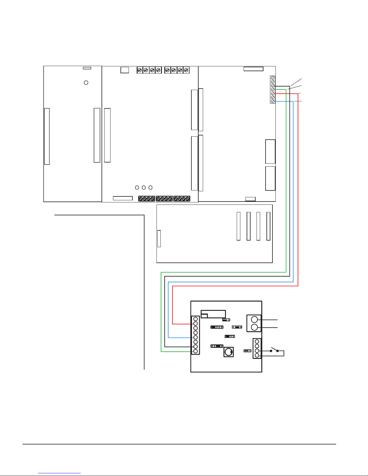
EVAX HMX
External Audio into HMX-MP
600 ohm balanced line, 25VRMS, or 70 VRMS input
EVX-ATM required if external
audio source is other than
600 ohm 1VRMS balanced.
See Page 2 for jumper settings
Field wiring connections:
#6-32 wire clamp screw 14-18 AWG
#8-32 wire clamp screw 12-18 AWG
Horizontal wire entry terminal 18-26 AWG
Wire gauge determined by circuit load
1
2
3
4
5
6
7
8
1
2
3
4
1
2
EVX-ATM
ABCD
J1
PQ
-
R
J2
J6
V
-
J4
1V
25V
70V
J3
15M
J5
XY
TB1TB2
TB3
VR1
P1


