EVE ANDER 90 User manual

Instruction Manual
Freestanding Cooker
ANDER 90

Dear Customer:
Thank you for choosing our product.
This appliance is easy to use; please read this manual carefully before installing and using the
appliance. The correct indications in the manual are for the best installation, use and care of the
appliance.
You will find that the clean lines and modern look of your oven blends in perfectly with your kitchen
decor. The oven is easy to use and performs to a high standard.
We also make a range of products that will enhance your kitchen - such as cook tops, Range hoods,
built- in hobs, built- in ceramic hobs and built- in ovens. These are models to complement your new
oven.
We make every effort to ensure that our products meet all your requirements. Our customer relations
department is at your disposal to answer all your questions and to listen to all your suggestions.
Please complete the warranty section of this manual and keep your receipt as proof of purchase.
Also please retain all documents related to the purchase of the product.
We are committed to provide increasingly efficient products that are easy to use, respect to
environmentally friendly, attractive and reliable.
1

2
Index
Instructions for installation:
Dimensions and installation features
Electrical connection
Ventilation and gas connection
Adaptation to different types of gas
Setting the minimum flame
Burner and injector characteristic table
Instructions for use
Description of the main parts of the appliance
Ignition and operation of the burners
Advice on the use of gas burners
Oven function
Electronic programmer
Maintenance and cleaning
CAUTIONS
Instructions for cooking
pag. 7
pag. 7
pag. 6
pag. 6
pag. 5
pag.3-4
pag. 17
pag. 15
pag. 13
pag. 9
pag. 10
pag. 11
pag. 12
pag. 11

CAUTIONS:
Very important: keep this instruction booklet with the appliance for handy references
This appliance is designed for use in private home. Please be aware that the front accessory could be not
to touch.
lIf a gas appliance is used for a long time it may require extra ventilation (opening a window or increase
the volume of exhaust).
lNever line the oven with aluminium sheets as the slots preset for keeping fast the thermic exchange may
clog, thus damaging the enamel.
lBe careful not to place saucepans with unstable or deformed bottoms on the burners to avoid overturning
or spilling .
This appliance shall be installed in accordance with the regulations in force and only used in a well
ventilated space. Read the instructions before installing or using this appliance.
l
l
lThis appliance is not intended for use by young children .
l Don't touch the heating elements inside the oven.
lWhen the grill is on all the accessible elements are hot, hence, keep children away from these elements.
l This appliance shall be installed only by authorised persons and in accordance with the manufacturer's
Installation instructions, local gas fitting regulations, municipal building codes electrical wiring
regulations,and local water supply regulations.
l Before switching the appliance on check that it is correctly regulated for the type of gas available (see
relevant section).
Do not use jet of steam for cleaning.
l Before maintenance or cleaning, disconnect the appliance from the mains and wait for it to cool down.
lWhen the burners are lit check that the flame is always regular. Before removing the saucepans turn the
burners off.
lServicing should be carried out only by authorised personnel.
lThe use of a gas appliance produces heat and humidity in the room . Make sure that the room is well
ventilated, keeping the natural ventilation outlets open or installing a ventilation hood with rain duct.
lIf the mains of a burner is turned off accidentally, turn off the control knob. Only light the oven again
after waiting at least a Minute.
Before using the oven, we suggest to:
lRemove all the special film covering the oven door glass (when provided)
lHeat the empty oven at max. Temperature for 45 minutes (to remove unpleasant smell and smoke caused
by working residues and by the thermal insulation)
lCarefully clean inside the oven with soapy water and rinse it .
lFor any repairs always contact an authorised Technical Customer Service Centre and ask for original
spare parts. Repairs by untrained people can lead to damage.
lKeep packaging out of reach of children at all times.
lAlways use oven gloves to remove and replace food in the oven. Ensure that you support the grill pan
when removing it from the oven.
lDon't let children sit down or play with the oven door.Do not use the drop down door as a stool to reach
cabinets above.
lDO NOT SPRAY AEROSOLS IN THE VICINITY OF THIS APPLIANCE WHILE IT IS IN OPERATION.
l DO NOT STORE OR USE FLAMMABLE LIQUIDS OR ITEMS IN THE VICINITY OF THIS
APPLIANCE.
lWHERE THIS APPLIANCE IS INSTALLED IN MARINE CRAFT OR IN CARAVANS, IT SHALL NOT
BE USED AS A SPACE HEATER .
lDo not remove the plup by pulling the cable.
WARNING: In order to prevent tipping of the appliance, this stabilizing means must be installed. Refer to the
instructions for installation.During use the appliance becomes hot. Care should be taken to avoid touching
heating elements inside the oven.
WARNING: Accessible parts may become hot during use. Young children should be kept away.
Do not use harsh abrasive cleaners or sharp metal scrapers to clean the oven door glass since they can scratch
the surface, which may result in shattering of the glass. This appliance is not intended for use by persons
(including children) with reduced physical,sensory or mental capabilities, or lack of experience and
3

Warning:
Never use the food-warmer drawer set at the bottom of the range to store
inflammable substances or matters that cannot withstand heat such as:
Wood, paper, spray cans, rags, etc.
This electric appliance complies with the following directives:
-89/336/EEC (electromagnetic compatibility)
-89/109/EEC (foodstuffs)
-73/23/EEC + 93/68/EEC (low voltage)
-2009/142/EC ( Gas Appliance Directive)
4
knowledge, unless they have been given supervision or instruction concerning use of the appliance by a
person responsible for their safety.Children should be supervised to ensure that they do not play with the
appliance.
lIf the supply cord is damaged, it must be replaced by the manufacturer, its service agent or similarly
qualified persons in order to avoid a hazard. In the event of burner flames being accidentally
extinguished,turn off the burner control and do not attempt to re-ignite the burner for at least 1 min.
lNote:These instructions are only valid if the country symbol appears on the appliance. If the symbol does
not appear on the appliance, it is necessary to refer to the technical instructions which will provide the
necessary instructions concerning modification of the appliance to the conditions of use of the country Gas
appliance
Instructions for Installation
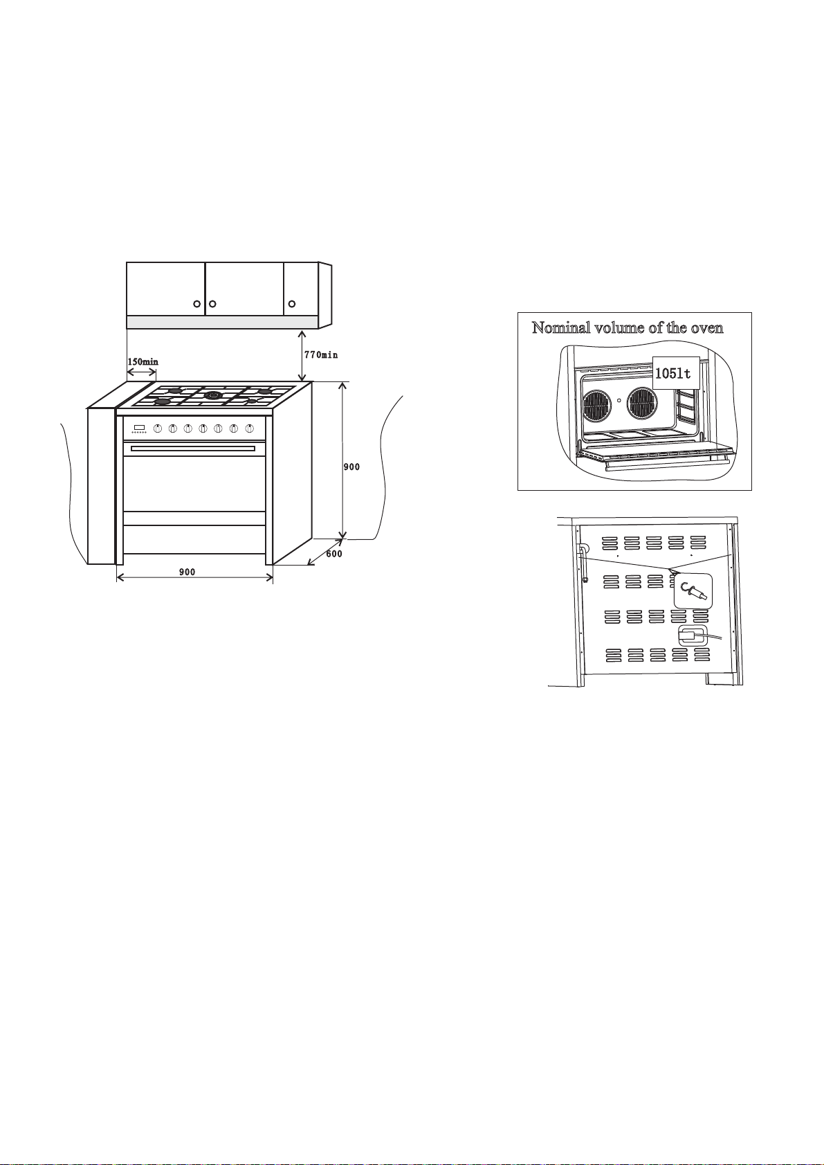
DIMENSIONS AND INSTALLATION FEATURES
Warning:
a) Prior to installation, ensure that the local distribution conditions (nature of the gas and gas pressure) and
the adjustment of the appliance are compatible;
b)The adjustment conditions for this appliance are stated on data plate;
c) This appliance is not connected to a combustion products evacuation device. It shall be installed and
connected in accordance with current installation regulations. Particular attention shall be given to the
relevant requirements regarding ventilation.
The cooker is supplied with an anti-tilting chain to prevent the appliance
from tilting forward and accidental damage to the gas pipe. Take the
expansion with hook and make an adequate hole in the wall behind, at the
same height as the chain fixing area. Insert the plug into the hole and then
screw in the hook until it is firmly fixed to the wall. Fix the chain to the
hook. Adjust to level of the cooker inserting the feet provided.
For a situation where the appliance is between two cupboards and the anti tilt chain cannot be fitted we
suggest securing by screwing through the both sides of the cupboards into the sides of the cooker. The screws
should be
fitted as follows. Position the oven between the cupboards in it's final position, then mark the location of the
pilot hole inside the cupboard. Refer to the diagram below for the location of the pilot hole. Use 3.5mm
diameter drill bit to drill the pilot hole through the cupboard and both sides of the cooker. Before drilling,
check your measurements to ensure the pilot holes are located within the range specified in the diagram. A
drilled hole in the
side of the cooker which is outside the range specified may void the warrantee. Inspect cupboards thoroughly
before drilling to avoid damage to electrical wires or gas lines. Fix two 12 gauge x 40mm long self tapping
screws through the pilot holes inside both cupboards and into the side of the cooker.
Note! Screw length is based on cupboard thickness of 20mm, gap between cupboard and oven of 10mm.
Screw length could vary depending on cupboard material thickness and gap between oven and cupboards.
Note! The screws must be accessible for removal if the cooker requires service. Cupboards must not be built
over these screws.
Equipment type: free standing (class 1)
Insulation class: class 1
THE MANUFACTURER DECLINES ANY AND ALL RESPONSIBILITIES FOR DAMAGES TO THINGS
OR INJURIES TO PERSONS OR ANIMALS DERIVING FROM INCORRECT INSTALLATION OR USE
OF THE EQUIPMENT.
Nominal volume of the oven
105lt
5
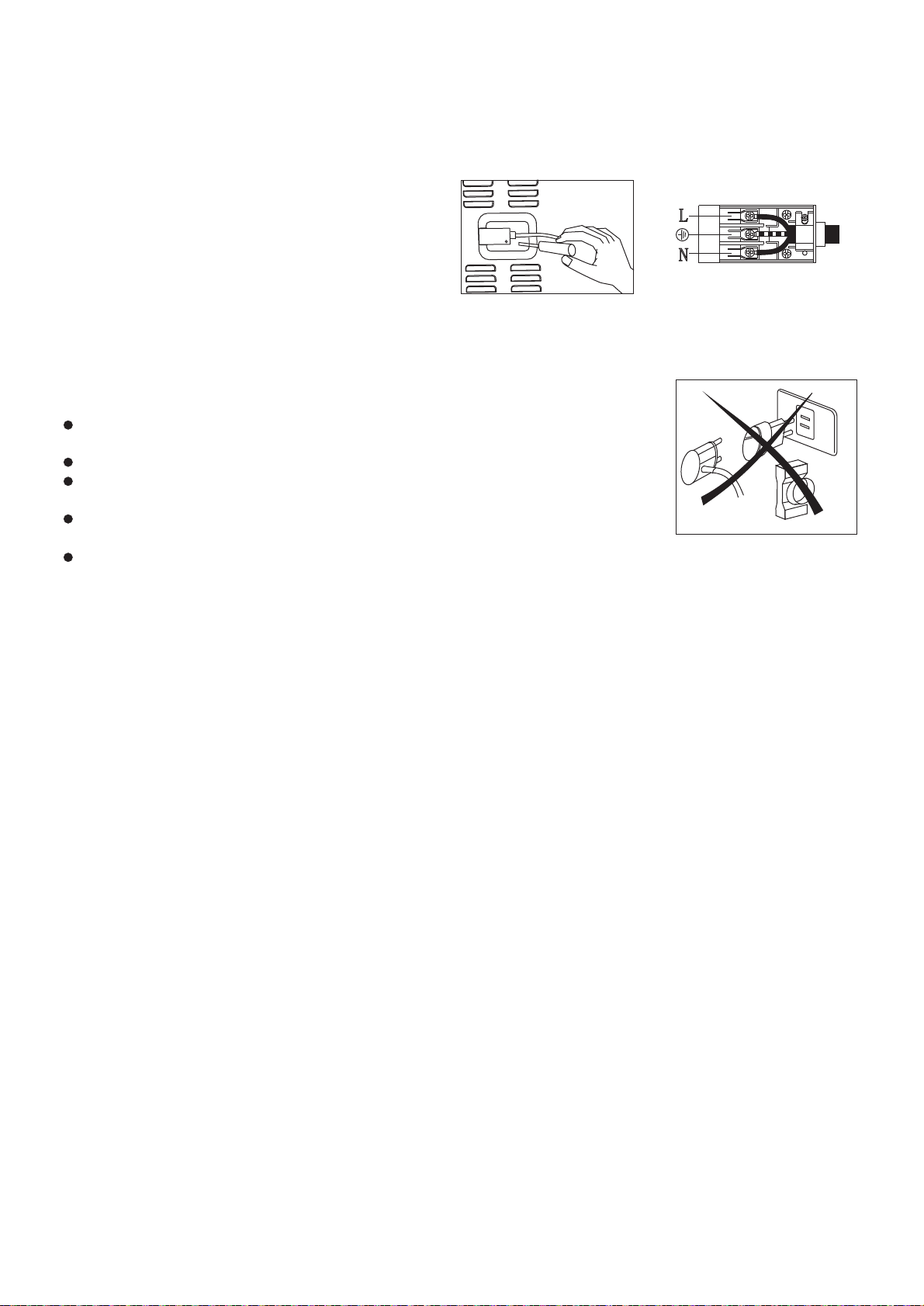
ELECTRICAL CONNECTION
The appliance is fitted with an approved 15 Amp flexible cord and plug which must be connected to a
correctly earthed socket outlet. The manufacturer is not liable for any direct or indirect damage caused by
faulty installation or connection. It is therefore necessary that all installation and connection operations are
carried out by qualified personnel complying with the local and general regulations in force.
The wire section on the cable must not be less
Than1.5mm (3×1.5cable).Use only the special
cables available at our service centers.
CONNECTION OF THE FEEDING CABLE TO THE MAINS
Connect the feeding cable to a plug suitable for the load indicated on the rating plate of the product. In case of
a direct connection to the mains (cable without plug), it is necessary to insert a suitable omnipolar switch
before the appliance, with minimum opening between contacts of 3 mm (the grounding wire should not be
interrupted by the switch).
Before connecting to the mains, make sure that:
The electrical counter, the safety valve, the feeding line and the socket are ade
quate towithstand the maximum load required(see rating plate).
The supply system is regularly grounded, according to the regulations in force.
The socket or the omnipolar switch can easily be reached after the installation
of the oven.
After carrying out the connection to the mains, check that the supplying cable
does not come into contact with parts subject to heating.
Never use reductions, shunts, adaptors which can cause overheating or burning.
The manufacturer is not liable for any direct or indirect damage caused by faulty installation or connection. It
is therefore necessary that all installation and connection operations are carried out by qualified personnel
complying with the local and general regulations in force.
Electrical features
Oven light 2×25W
2200W
1800W
2900W
2×1250W
Upper heating element
Bottom heating element
Grill heating element
Circular heating element
This appliance shall be installed only by authorised persons and in accordance with the manufacturer's
installation instructions, local gas fitting regulations, municipal building codes, electrical wiring
regulations, local water supply regulations.
Ventilation
In general, the appliance should have adequate ventilation for complete combustion of gas, proper flueing
and to maintain temperature of immediate surroundings within safe limits.
Combustible Surfaces
Any adjoining wall surface situated within 200mm from the edge of any hob burner must be a suitable non-
combustible material for a height of 150mm for the entire length of the hob. Any combustible construction
above the hotplate must be at least 600mm above the top of the burner and no construction shall be within
450mm above the top of the burner. Zero clearance is permitted on side and rear adjoining surfaces below the
hob.
Gas connection
The appliance must be connected to the gas supply or the cylinder according to the specifications of the
standards and after checking that it is adjusted for the type of gas available.
The gas connection is male 1/2"BSP and is situated 55mm from the right and 560mm from the floor.
There are two ways to carry out
the connection to the main gas line:
A. The Cooker can be connected with the cuprum material . Loosen the tie-in down and connect one terminal
of the pipe with the gas elbow
It's
necessity of changing the flexible tube whenthe national conditions require it.
2L
N
6

between 1 - 1.2m long. The hose should not be subjected to abrasion, kinking or permanent deformation and
should be able to be inspected along its entire length. Unions compatible with the hose fittings must be used
and connections tested for gas leaks.
.The fixed consumer piping outlet should be at approximately the same
height as the cooker connection point, pointing downwards and approximately 150mm to the side of the
cooker. The hose should be clear of the floor when the cooker is in the installed position. Fix one end of the
chain on the screw next to the gas inlet connection and the other end should be anchored to the floor/wall so
that the chain prevents strain on the hose connections when he cooker is pulled forward.
The appliance is factory set for Natural gas. The test point pressure should be adjusted to with the
Triple ring burner operating at maximum.
The appliance is set up to operate with the gas specified on the gas type label placed on the back of the
appliance.
To perform these operations the qualified installer will follow the indications given in the "Adaptation to the
various types of gas" section. For safer operation make sure that the supply pressure respects the values given
in the "Table of burner and injector characteristics".
If installing for use with gas, ensure a gas regulator suitable for a supply pressure of is part of the
gas tank supply and the test point pressure is adjusted to .
Once the appliance has been installed, make sure that the gas pipe is neither squashed or damaged by moving
parts.
Before Leaving - Check all connections for gas leaks with soap and water. DO NOT use a naked flame for
detecting leaks. Ignite all burners both individually and separately to ensure correct operation of gas valves,
burners and ignition. Turn gas taps to low flame position and observe stability of the flame for each burner
individually and separately. When satisfied with the operation of the cooker, please instruct the user on the
correct method of operation. In case the appliance fails to operate correctly after all checks have been carried
out, refer to the authorised service provider in your area.
Adaptation to different types of gas
To adapt the appliance to a gas different from that
for which it was set up (see gas type label inside
the warming compartment door) proceed as follows:
remove the grids
remove the burners caps and burner heads
with a 7 mm socket spanner unscrew and remove the injectors.
replace the injectors with those supplied corresponding to the
gas available (see burner and injector characteristics Table)
replace the various parts proceeding in reverse.
When converting from Natural Gas to ensure that theNG regulator is removed and replaced with the Test
Point Assembly. A gas regulator suitable for a supply pressure of should be part of the gas tank supply and the
test point pressure should be adjusted to
Setting the minimum flame
The flame on the small output is regulated by the factory.
When the injectors have been replaced or there are special
mains pressure conditions, it may be necessary to regulate
the minimum flame again. The operations necessary to set
the minimum flame are as following:
light the burner ;
turn the knob to the minimum position ;
take out the knob (and gasket if there is one) ;
The flexible tube shall be fitted in such a way that it cannot come into
contact with a moveable part of the housing unit (e.g. a drawer)and does not pass through any space
susceptible of becoming congested
20mbar
LPG 29mbar
29mbar
When converting from Universal LPG to Natural Gas ensure that the LPG test point is removed and replaced
with the CE Approved NG Regulator supplied in this kit. The test point pressure must be adjusted to
20mbar with the largest burner operating on maximum flame.
When converting from Natural Gas to Universal LPG ensure that the NG regulator is removed and replaced
with the Test Point Assembly supplied in this kit. An CE Approved gas regulator suitablefor a supply pressure
of 29mbar should be part of the gas tank supply and the test point pressure must be adjusted to 29mbar.
LPG
the pressure according to the data plate.
l
l
l
l
l
l
l
l
7
If installing for use with gas, ensure a gas regulator suitable for a supply pressure of is part of the
gas tank supply and the test point pressure is adjusted to .
TG 8mbar
8mbar

8
THE BURNERS REQUIRE NO REGULATION OF THE PRIMARY AIR.
ABNORMAL OPERATION
ANY OF THE FOLLOWING ARE CONSIDERED TO BE ABNORMAL OPERATION
AND MAY REQUIRE SERVICING:
l Yellow tipping of the hob burner flame.
lSooting up of cooking utensils.
lBurners not igniting properly.
lBurners failing to remain alight.
lBurners extinguished by oven door.
lGas valves, which are difficult to turn.
IN CASE THE APPLIANCE FAILS TO OPERATE CORRECTLY, CONTACT
THE AUTHORISED SERVICE PROVIDER IN YOUR AREA.
lput the knob back on and turn it quickly from the maximum position to the minimum position, checking
that the flame does not go out ;
l for burners with safety valve make sure that the regulation obtained is sufficient to maintain heating of
the thermocouple. If it is not, increase the minimum
l
l
LPG TO TG:Use a thin blade screwdriver to turn the by-pass screw located above left of the gas
valve,shaft as shown right. Turn gently the by-pass screw clockwise to the end completely then turn it
anti-clockwise turn for the Triple ring, turn for the Fish, turn for the Rapid, turn for the Semi-
Rapid and turn for the Auxiliary .
TG TO LPG: Use a thin blade screwdriver to turn the by-pass screw located above left of the gas valve
shaft as shown right.Turn gently the by-pass screw clockwise to the end.
l
l
LPG TO NG:Use a thin blade screwdriver to turn the by-pass screw located above left of the gas
valve,shaft as shown right. Turn gently the by-pass screw clockwise to the end completely then turn it
anti-clockwise 1 turn for the Triple ring,7/8 turn for the Fish,3/4 turn for the Rapid,1/2 turn for the Semi-
Rapid and 3/8 turn for the Auxiliary .
NG TO LPG: Use a thin blade screwdriver to turn the by-pass screw located above left of the gas valve
shaft as shown right.Turn gently the by-pass screw clockwise to the end.
41
217
813
4
13
8
11
2
l
l
NG TO TG:Use a thin blade screwdriver to turn the by-pass screw located above left of the gas
valve,shaft as shown right. Turn gently the by-pass screw clockwise to the end completely then turn it
anti-clockwise turn for the Triple ring, turn for the Fish, turn for the Rapid, turn for the Semi-
Rapid and turn for the Auxiliary .
TG to NG:Use a thin blade screwdriver to turn the by-pass screw located above left of the gas valve,shaft
as shown right. Turn gently the by-pass screw clockwise to the end completely then turn it anti-
clockwise turn for the Triple ring, turn for the Fish, turn for the Rapid, turn for the Semi-Rapid
and turn for the Auxiliary .
31
21 1
1
1
31
2111
1

Table of contents


