Everest TWIN LOBE User manual
DO NOT OPERATE WITHOUT
READING MANUAL
WARNING Publication No. OMM_Everest Blowers
Rev 3, September 2017
INSTALLATION | OPERATION | MAINTENANCE
TWIN LOBE
& TRI LOBE
PD BLOWERS
EVEREST ROTARY BLOWER INSTRUCTION MANUAL
© Everest Blowers www.everestblowers.com 1
Contents Pg. No.
To Get The Most From Your Everest Blower
Safety Precautions
Working Principle
Introduction - Your Key To Trouble Free Service
Equipment Check & Storage
2
3
4
6
7
Installation 8
Instruction Manual
INDEX
Drive Installation 9
Recommended Layout For Multiple Blowers Installation 10
Auxiliary Equipment 11
Accessories Layout For Everest Blowers 14
Lubrication 15
Special Note for Water Cooled & Gas~Biogas Blowers 18
Orientation of Blowers
18
19
24
27
Spares & Consumables
Blower Startup Checklist
Fault Chart
Everest Wants To Know What You Think - Feedback Form
Notes
Trouble Shooting 21
23
20
Instruction Manual
TO GET THE MOST FROM YOUR “EVEREST” BLOWER
1.0 Make sure proper oil levels are maintained in the gear end and grease/oil in the drive
end.
2.0 Check oil level and grease every 40 hours of operation. Loss of oil or grease should be
replenished.
3.0 First oil change should be done within the first 100 operating hours and thereafter
every 1000 hours or more often, if oil gets dirty.
4.0 Check belt tension every fortnight. Too tight belts would cause premature bearing
failure while too loose belts would cause overheating of belts and pulleys.
5.0 Check regularly for any knocking or abnormal sound. High frequency sound indicates
bearing trouble. Knocking sound indicates rotor timing upset. Contact “Everest” for
necessary adjustments.
6.0 Clean air filter every fortnight by reverse airflow. Chocked filter would result in
excessive power consumption and overheating of blower. Replace filter every three
months or earlier.
7.0 Check and clean air silencer every month.
© Everest Blowers 2
www.everestblowers.com 2
CAUTION
Everest Blower is shipped without oil.
Before operating, put the required amount of oil into the reservoirs as per
instructions under lubrication.
Do not fill oil reservoirs until blower is mounted in its operating location.
NOTICE
Everest Blowers are meant for indoor installation or should be protected
from direct rain and sunlight, if installed outdoor.
WARNING
Instruction Manual
© Everest Blowers 2
www.everestblowers.com 3
SAFETY PRECAUTIONS
Safety is everybody’s business and is based on your good use of common sense. All situations or
circumstances cannot always be predicted and covered by established rules. Therefore, use your
past experience, watch out safety hazards and be cautious. Some general safety precautions are
given below.
DANGER
Failure to observe these notices could result in injury or death of personal.
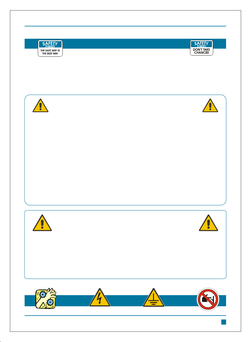
Keep fingers and clothing away from blower inlet and discharge ports, revolving
belts, pulleys, drive coupling etc.
Do not use the air discharged from this unit for breathing - not suitable for human
consumption.
Do not loosen or remove the oil fill plug, drain plug, covers or break any
connections, etc., in the air or oil system until the unit is shut down and the air
pressure has been relieved.
Electric shock can and may be fatal.
Open main, disconnect switch, tag and lockout before working on the control.
Disconnect the Blower unit from its power source, tag and lockout before
working on the unit.
Failure to observe these notices could result in damage to equipment.
Stop the unit if any repairs or adjustments on or around the Blower are required.
Disconnect the Blower unit from its power source, tag and lockout before
working on the unit.
Do not operate unit if safety devices are not operating properly. Check
periodically. Avoid bypassing safety devices.

Instruction Manual
© Everest Blowers 2
www.everestblowers.com 4
EVEREST TWIN LOBE ROTARY AIR BLOWER WORKING PRINCIPLE
Everest Twin Lobe Rotary Compressors/Blowers are positive displacement units, whose pumping
capacity is determined by size, operating speed and pressure conditions. It employs two Twin
Lobe impellers mounted on parallel shafts, rotating in opposite direction within a casing closed at
the ends by side plates. As the impellers rotate, air is drawn into one side of the casing and forced
out of the opposite side against the existing pressures. The differential pressure developed,
therefore, depends upon the resistance of the connected system. The Blowers, being positive
displacement type, do not develop pressure within the casing but the discharge pressure depends
upon the system resistance / back pressure. Effective sealing of the compressor inlet area from
the discharge area is accomplished by use of very small operational clearance, eliminating the
need of any internal lubrication of the lobes. A pair of accurately machined alloy steel, hardened
and ground timing gears maintain clearances between the impellers, during rotation. The air, thus
delivered, is 100% OIL FREE.
The pumping capacity of a lobe compressor, operating at constant speed remains relatively
independent of inlet and discharge pressure variations. These Blowers are constant volume
machines, which deliver a fixed discharge against the system back pressure. It is, therefore,
essential to ensure that minimum pipeline restrictions, at the inlet and discharge, are imposed.
Adequate size piping and large radius bends ensure minimum line losses resulting in higher
efficiency and low power consumption. Sudden change in pipeline cross section should also be
avoided.
To change capacity, it is necessary either to change speed (energy saving) or vent some of the air
into atmosphere (not energy saving). The air must not be recirculated from the discharge to
suction as it may result in over heating. No attempt should ever be made to control the capacity of
compressor by means of throttle valves in the intake or discharge piping. This increases the power
load on the motor and may seriously damage the compressor. There is an increase in the
discharge air temperature due to heat of compression. As a thumb rule the discharge air
o 2
temperature increases @ 10 C for every 0.1 Kg/cm of ∆ P above the inlet temperature.
POSITION-1 POSITION-2 POSITION-3 POSITION-4

Instruction Manual
© Everest Blowers 2
www.everestblowers.com 5
EVEREST TRI LOBE ROTARY AIR BLOWER WORKING PRINCIPLE
Everest Tri-lobe Rotary Compressors/Blowers are positive displacement units, whose pumping
capacity is determined by size, operating speed and pressure conditions. It employs two Tri-lobe
impellers mounted on parallel shafts, rotating in opposite direction within a casing closed at the
ends by side plates. As the impellers rotate, air is drawn into one side of the casing and forced out
of the opposite side against the existing pressures. The differential pressure developed, therefore,
depends upon the resistance of the connected system. The Blowers, being positive displacement
type, do not develop pressure within the casing but the discharge pressure depends upon the
system resistance / back pressure. Effective sealing of the compressor inlet area from the
discharge area is accomplished by use of very small operational clearance, eliminating the need
of any internal lubrication of the lobes. A pair of accurately machined alloy steel, hardened and
ground timing gears maintain clearances between the impellers, during rotation. The air, thus
delivered, is 100% OIL FREE.
The pumping capacity of a lobe compressor, operating at constant speed remains relatively
independent of inlet and discharge pressure variations. These Blowers are constant volume
machines, which deliver a fixed discharge against the system back pressure. It is, therefore,
essential to ensure that minimum pipeline restrictions, at the inlet and discharge, are imposed.
Adequate size piping and large radius bends ensure minimum line losses resulting in higher
efficiency and low power consumption. Sudden change in pipeline cross section should also be
avoided.
To change capacity, it is necessary either to change speed (energy saving) or vent some of the air
into atmosphere (not energy saving). The air must not be recirculated from the discharge to
suction as it may result in over heating. No attempt should ever be made to control the capacity of
compressor by means of throttle valves in the intake or discharge piping. This increases the power
load on the motor and may seriously damage the compressor. There is an increase in the
discharge air temperature due to heat of compression. As a thumb rule the discharge air
o 2
temperature increases @ 10 C for every 0.1 Kg/cm of ∆ P above the inlet temperature.
POSITION-1 POSITION-2 POSITION-3 POSITION-4
Instruction Manual
© Everest Blowers 2
www.everestblowers.com 6
INTRODUCTION - YOUR KEY TO TROUBLE FREE SERVICE
Thank you for investing in Everest quality. The Everest reputation for rugged dependability has
been earned by over 37 years of service in demanding, industrial operations where downtime
cannot be tolerated and efficient blower performance is expected. Your Everest Blower is a
precision-engineered blower that has been carefully manufactured and thoroughly tested at the
state-of-the-art Everest Blowers factory.
As with other precision machinery, there are several relatively simple installation, operation and
maintenance procedures that you must observe for optimum blower performance. There is no
guesswork in the manufacture of your highly advanced Everest Blower and there must be none in
preparing the Blower to get the job done in the field.
The purpose of this manual is to help you properly install, operate and maintain your Everest
Blower. It is essential that you review all sections of this manual in preparation for installing your
blower. Follow the instructions carefully and you will be rewarded with trouble free Everest
service................year in and year out.
WHERE TO CALL FOR EVEREST BLOWER ASSISTANCE:
For prompt professional Everest service always contact your authorized Everest Distributor First.
If you do not know your authorized Everest Distributor, contact the numbers below for immediate
assistance.
EVEREST CUSTOMER SERVICE / FACTORY SERVICE DEPARTMENT
EVEREST BLOWERS PVT. LTD.
B-44 MAYAPURI INDUSTRIAL AREA, PHASE - 1,
NEW DELHI - 110064, INDIA.
Ph : 91 - 11 - 45457740 | Fax: 91-11-45457718
Email : [email protected]
WARNING
Customers are cautioned to provide adequate protection, warning and safety
equipment necessary to protect personnel against hazards involved in installation
and operation of this equipment in the system or facility.
Instruction Manual
© Everest Blowers 2
www.everestblowers.com 7
EQUIPMENT CHECK & STORAGE
EQUIPMENT CHECK:
On uncrating, check the packing slip carefully to be sure all the parts have been received. All
accessories are listed as separate items on the packing slip, and small important accessories
such as relief valves, can be overlooked or lost. After every item on the packing slip has been
checked off, unpack carefully. Register a claim with the carrier for lost or damaged equipment.
STORAGE:
Your Everest Blower was packed at the factory with adequate protection to permit normal storage
for upto three (3) months. If the unit is to be stored under adverse conditions or extended period of
time, the following additional measures should be taken to prevent damage.
1 Store the Blower in a clean, dry area.
2 Make certain inlet and discharge air ports are tightly covered to prevent foreign material from
entering the air box.
3 All exposed, non-painted surfaces should be protected against rust and corrosion.
4 Provide adequate protection to avoid accidental /mechanical damage.
5 In high humidity or corrosive environments, additional measures may be required to prevent
rusting of the Blower internal surfaces.
6 To prevent rusting of gears, bearings etc., the oil reservoirs may be filled with normal
operating oil.
7 Rotate the Blower shaft (10 to 25 turns) monthly during storage. Inspect the Blower shaft
(near shaft seal area) monthly and spray with rust inhibitor if needed.
8 For long-term storage (over six (6) months) contact Everest Customer Care for
recommendations.
REMOVING PROTECTIVE MATERIALS:
The shaft extension is protected with rust inhibitor that can be removed with any standard solvent.
Alternatively the Blower pulley is factory fitted on the shaft extension and it requires no cleaning.
Blower inlet & outlet are temporarily capped to keep out dirt and other contaminants during
shipment. These covers must be removed before start-up. Keep them intact during the period of
storage.
Everest Blowers are internally and externally treated to protect against normal atmospheric
corrosion. Prior to installation remove covers from Blower inlet and discharge openings and
inspect internals. If the cleaning is required, clean the internals thoroughly using any commercial
solvent (e.g. Kerosene / Diesel). Continue this procedure until the unit is visibly clean. Check the
drive shaft by rotating manually to ensure the impellers turn freely at all points. No internal
adjustment is generally required.
LOCATION:
If possible, install the Blower in a well-lit, clean, dry place with plenty of room for inspection and
maintenance. Protection from direct sunlight and rainwater is required. Effect of location on driver
and accessory equipment must also be considered.
FOUNDATIONS:
For permanent installations we recommend concrete foundations be provided, and the equipment
must be leveled, free of all strains, and anchored so no movement will occur during setting of grout.
After grout has completely hardened, a recheck is necessary to compensate for shrinkage etc. If
required add shims under Blower feet before final tightening of foundation bolts to remove strain
from the Blower housing. Blower assembly can be mounted on Anti Vibration Pads and directly
placed on leveled concrete surface.
Instruction Manual
© Everest Blowers 2
www.everestblowers.com 8
INSTALLATION
WARNING
Rotating components will cause severe injury in case of personal
contact. Keep hands away from blower inlet and discharge ports.
WARNING
Handling of equipment needs to be accomplished with care,
and in compliance with safe practices.

DIRECT DRIVE (COUPLED):
On the direct connected units, alignment and lubrication of couplings to specifications of the
coupling manufacturer is very important. When mounted drives are supplied from the factory,
proper alignment has been established before shipment. However, during shipping, handling and
installation, it is likely that the alignment has been disturbed and final adjustment must be made
before start up. A flexible type coupling should always be used to connect the driver and blower
shaft.
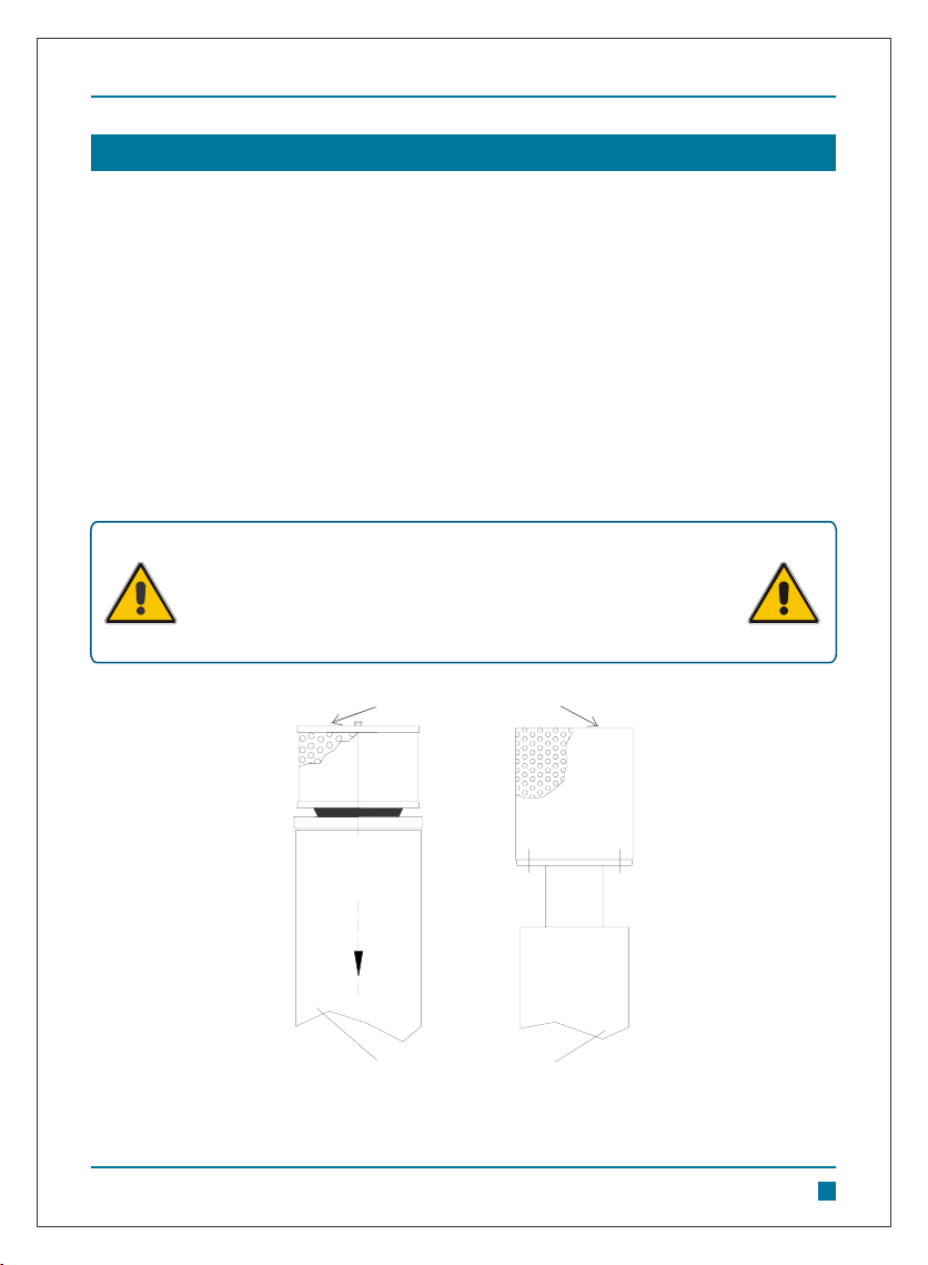
BELT DRIVE:
Belt drives must be carefully aligned. Motor and blower pulleys must be parallel to each other and
in the same plane. Belt tension should be carefully adjusted to the belt manufacturers
recommendation using a belt tension gauge. Check tension frequently during the first day of
operation.
The location of pulley on the Blower shaft greatly affects the stress in the shaft. The optimum
blower pulley positioning is as close as possible to the blower drive shaft bearing cover, to
minimize overhung loads.
PIPING:
Inlet and discharge connections on all blowers are large enough to handle maximum volumes with
minimum friction loss. Reducing the pipe diameter on either inlet or discharge will only create
additional line loss and increase the overall differential pressure and input power.
Pipe threads / flanges (suction and discharge) must meet the blower connections accurately and
connections by springing or cramping the pipe or by forcefully connecting the two may result in
distorting the blower casing and thereby causing serious damage to the Blower. For similar
reasons, piping should be supported near the blower to eliminate dead weight strains on the
blower. A flexible pipe bellow is recommended in the discharge pipeline, close to the blower
discharge, so as to isolate blower and pipeline vibrations.
Instruction Manual
© Everest Blowers 2
www.everestblowers.com 9
WARNING
Misalignment of coupling halves leads to unwarrantable
premature bearing failure and shaft breakage.
WARNING
Over tightened belts lead to heavy bearing loads and shaft
deflections and may result in premature failure of bearings / shafts.
DRIVE INSTALLATION
Avoid sharp bends in the suction and discharge line. Use adequate size pipe with large radius
bends. This would keep pipeline pressure losses to bare minimum. As a thumb rule the line size
should be such that the air velocity is in the range of 20-25 m/sec. Gate valves, nozzles etc. should
be avoided, since they cause turbulence and have not much utility. If at all they must be used,
ensure they are sized properly.
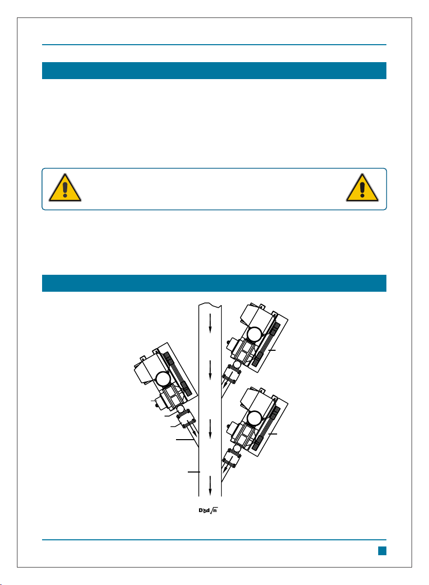
MULTIPLE BLOWER INSTALLATIONS:
When two or more blower are connected to a system through a common header, the line sizes
should be adequately designed to handle the flow rates. Generous line sizes would result in low
line losses and consequently power saving. Refer to proposed layouts as shown below:
EVEREST
BLOWER NO. 2
RELIEF VALVE
NON RETURN VALVE
LINE Ød
COMMON HEADER
LINE ØD
EVEREST
BLOWER NO. 3
EVEREST
BLOWER NO. 1
TO SYSTEM
WHERE D = MAIN HEADER LINE DIAMETER
d = BLOWER DISCHARGE LINE DIAMETER
n = NUMBER OF BLOWERS
Instruction Manual
© Everest Blowers 2
www.everestblowers.com 10
DRIVE INSTALLATION
All system piping must be cleaned internally before connecting
to the Blower
RECOMMENDED LAYOUT FOR MULTIPLE BLOWERS INSTALLATION
WARNING
The auxiliary items that might be required under various operating conditions are:
SILENCERS:
The need for silencer depends on Blower speed and pressure as well as sound level requirements
in the general surroundings. Silencers should be mounted as close to the blower as possible.
SUCTION FILTER:
An inlet filter is generally recommended, especially in dusty locations, as it safeguards the
machine against dirt and dust. The filter should be periodically checked for choking. Choking of
filter would result in pressure drop across it thereby increasing the load on the Blower marked by
increase in power intake. The filter element should be regularly cleaned by reverse jet of air. The
pressure drop across the filter should not exceed 100mm WG. Replace filter every three months.
Clean Air Filter every fortnight by reverse air flow. Chocked filter would result in excessive power
consumption and overheating of the blower. Replace filter every three months or earlier, if
inspection so demands. Check and clean Air Silencer every month.
Instruction Manual
© Everest Blowers 2
www.everestblowers.com 11
AUXILIARY EQUIPMENT
Choking of suction filter leads to increased load on the blower.
Replace filter every three months. Servicing the air filter is one of
the most important maintenance operations to be performed
periodically to ensure long blower life.
WARNING
SUCTION SILENCER
SUCTION AIR FILTER

RELIEF VALVE NORMAL POSITION RELIEF VALVE OVERLOADED POSITION
DISCHARGE PIPE LINE DISCHARGE PIPE LINE
SAFETY RELIEF VALVE
Fig: Relief Valve Operation Illustration
PRESSURE RELIEF VALVE:
A pressure relief valve is necessary in the discharge pipe to protect against any overloading in the
discharge line. In case of discharge line pressure exceeding the set limits, the valve cap pops up,
discharging air into atmosphere.
NON RETURN VALVE (OPTIONAL):
Non-return valve may be fitted close to the discharge port to prevent the compressor from running
in the reverse direction, when switched off under load conditions. In multiple blower installations
when two or more units discharge into a common header, use of non return valves is
recommended. One non-return valve should be located in each blower discharge line. Properly
installed, they will protect against damage from reverse rotation caused by air back flow through
an idle blower.
Instruction Manual
© Everest Blowers 2
www.everestblowers.com 12
AUXILIARY EQUIPMENT
Relief valve should be placed as close as possible to the Blower
discharge. They are not meant to discharge full capacity and
therefore cannot be taken as safefuard against total blockage.
NOTICE

WRONG
RIGHT
MEASURING AND MONITORING DEVICES:
Pressure gauge is supplied along with the supply and it is recommended to connect it to the
discharge pipe line, close to the blower, to ensure that the system pressure is within
the Blower rated pressure. However, U-Tube Mercury manometer may be used for
more accurate observations. Special measuring and monitoring systems can be
connected as per the individual requirement.
CAPACITY CONTROL:
The capacity of the blower can be varied by changing the blower speed, however, confirmation to
the input power and maximum speed must be made prior to doing so. No valves should be put into
the suction / discharge line to regulate the air capacity. One may, however, vary the discharge air
capacity by venting out some of the air into atmosphere. Refer illustration below.
Instruction Manual
© Everest Blowers 2
www.everestblowers.com 13
CAPACITY CONTROL
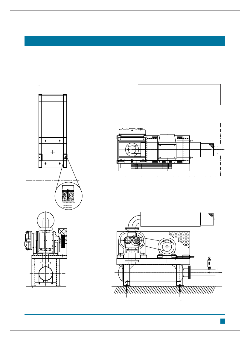
G.A. drawing for a typical Everest Blower. G.A. drawing of your particular Everest Blower was
issued alongwith P.O. Acknowledgment, sectional drawing & bill of material. You may request for
another copy of the same giving reference of P.O. No. & Date and Blower Model & Serial Number.
Instruction Manual
© Everest Blowers 2
www.everestblowers.com 14
ACCESSORIES LAYOUT FOR EVEREST BLOWERS
FOUNDATION
PLAN
MOTOR
BLOWER
ELEVATION
SIDE VIEW
PLAN
Note:
1. Direction Of Rotation Clockwise As Viewed.
2. Protect From Direct Sunlight & Rain.
3. Blower Opening Detail : 100 mm NB
Instruction Manual
© Everest Blowers www.everestblowers.com
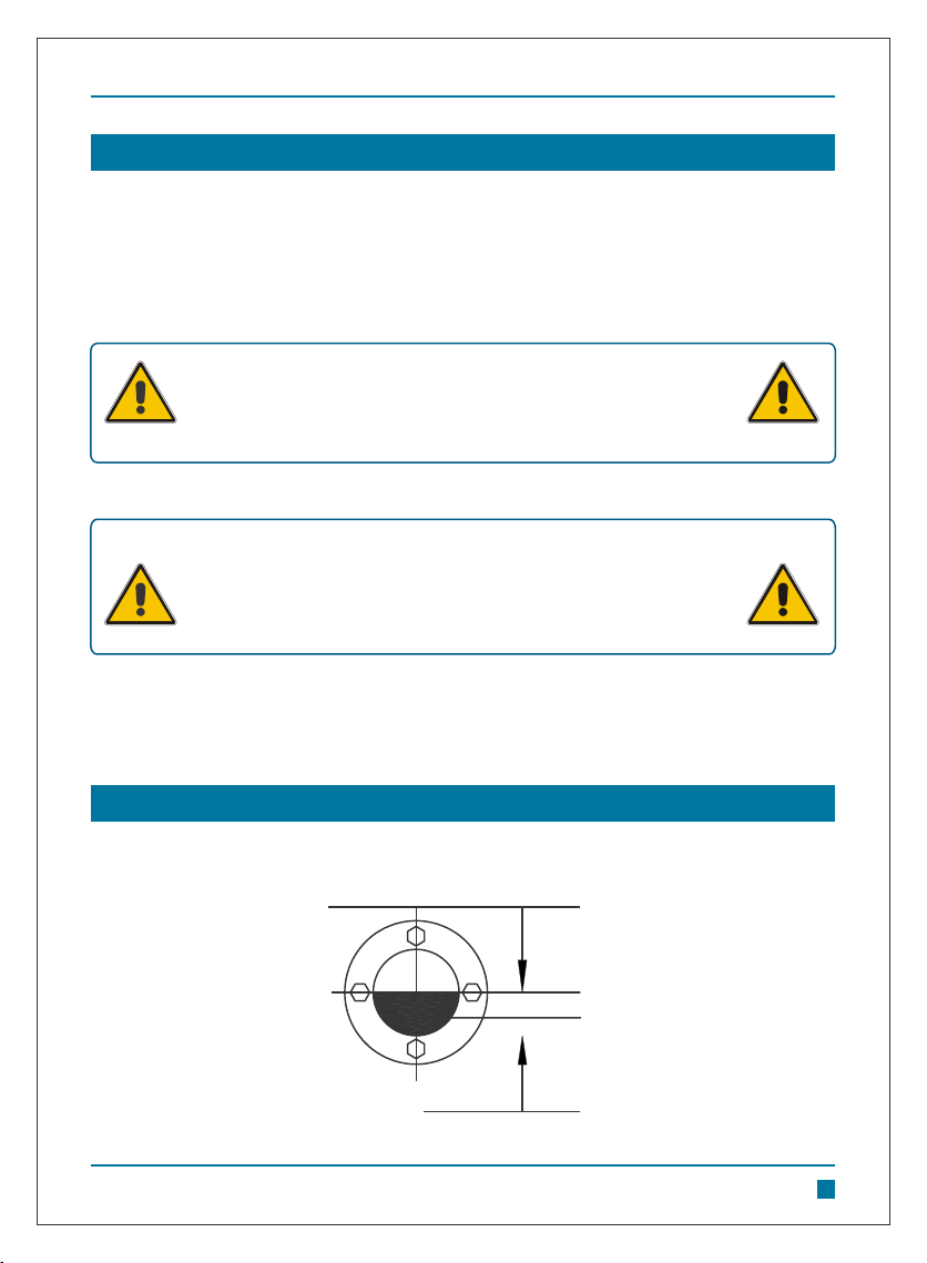
LUBRICATION
EVEREST Twin Lobe Rotary Air Blowers have a very simple yet effective lubrication systems. At
the gear end, the timing gear teeth are lubricated by being partially submerged in oil. A good grade
industrial type, rust oxidation and foam inhibited, non-detergent gear oil (of medium viscosity) is
recommended. The oil level indicator is provided at the back of the gear cover to monitor oil level.
The oil should be periodically checked and fresh oil added as required to maintain proper level.
During complete oil change old oil should be drained, gear cover flushed and then new oil added.
The Blower drive end bearings are OIL / GREASE Lubricated.
A weekly check for oil, under normal conditions, ensure longer blower life. Refer Lubrication
diagram as shown below.
First oil change should be done within first 100 operating hours
and thereafter, complete oil change is recommended after about
1000 operating hours or earlier if inspection so indicates.
The recommended oil grade is Shell Spirax S2 G 90 / Indian Oil
Servo Gear HP 90 / Castrol Hypoy EP 90 / HP Gear Oil EP 90 / MAK
Spirol EP 90 / Indian Oil Servo Gear Super 90. Recommended
grease grade is Castrol AP2 / AP3.
LUBRICATION DIAGRAM
CORRECT OIL LEVEL.
BLOWER NOT OPERATING.
LOW OIL LEVEL
2
15
WARNING
WARNING
Instruction Manual
© Everest Blowers 2
www.everestblowers.com 16
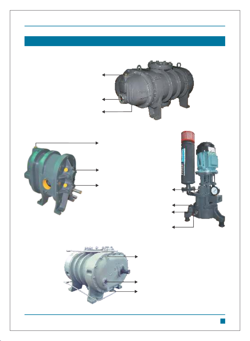
LUBRICATION DIAGRAM
OIL FILL PLUG
OIL DRAIN PLUG
OIL LEVEL INDICATOR
OIL FILL PLUG
GREASE CUP
GREASE CUP
OIL LEVEL INDICATOR
OIL FILL PLUG
OIL DRAIN PLUG
Lubrication points for different blower configurations.
OIL FILL PLUG
OIL LEVEL INDICATOR
OIL DRAIN PLUG
GREASE NIPPLE
Instruction Manual
© Everest Blowers 2
www.everestblowers.com 17
Correct lubrication is probably the most important requirement, other than operating the blower
within its specific rating limits. In a blower there are no moving contacts between the two impellers
or between impellers and the body or side plates. The wear is then, confined to the timing gears,
the bearings and the shaft seals. All are lubricated and wear would be nominal if clean oil of proper
grade is always used.
Timing gears wear should be negligible over the normal period of service. Gear teeth are hardened
and ground to super finish. A reasonable degree of tooth wears, which normally can be
accommodated without permitting contact between lobes.
However, high oil level in the gearbox would cause churning and excessive oil heating usually
indicated by high temperature at the bottom of the sump. If operation is continued under this
condition, gear will wear and tooth clearance will be lost. Rapid tooth wear will then probably
develop, which will eventually produce impeller knocking. From this point serious damage will be
unavoidable if operations are continued. Tooth fracture, brought on by sustained overloading and
shock loads would produce similar results suddenly. Shaft bearings are critical in the service life of
the Blower. Gradual wear may allow shaft position to change slightly until rubbing develops
between impellers and casing or plates. Sudden bearing failure is usually more serious. Since the
impellers shaft assembly is no longer supported and properly located, extensive damage is likely
to occur if operation is continued. It has been observed that main cause of premature sudden
bearing failure is either lack of lubrication or contamination. It is, therefore, strongly advised to take
all the necessary steps to ensure proper, clean lubrication of gears and bearings.
Do not overfill. This will cause excessive heating of the gears and
may damage the unit.
WARNING
Ensure Lubrication of Bearings and Gears is regularly maintained.
This avoids premature failure of Blower.
Provide suitable protection / cover to prevent Lubricant getting
contaminated by dust, dirt and water as these render it ineffective.
WARNING
Instruction Manual
© Everest Blowers 2
www.everestblowers.com 18
SPECIAL NOTE FOR WATER COOLED & GAS~BIOGAS BLOWERS
Pressure duty air blowers are not recommended for use in Gas~Biogas and Vacuum duty
applications.
Water cooled blowers are similar to air cooled blowers except for the provision for cooling of end
plates by water circulation in water cooled blowers. Water cooled blowers are recommended for
applications where differential pressure (∆ P) across the blower is high or inlet gas temperature is
high. The objective is to cool the lubricant & bearings and not the discharge gas.
Incase of Gas~Biogas blowers, vacuum switch may be provided at the inlet of the blower, so that
incase the biogas generation falls below the pumping speed of the blower, the blower trips and this
prevents vacuum overloading. Similarly, a pressure switch may be installed on the discharge line
to safeguard the blower against excessive discharge pressures.
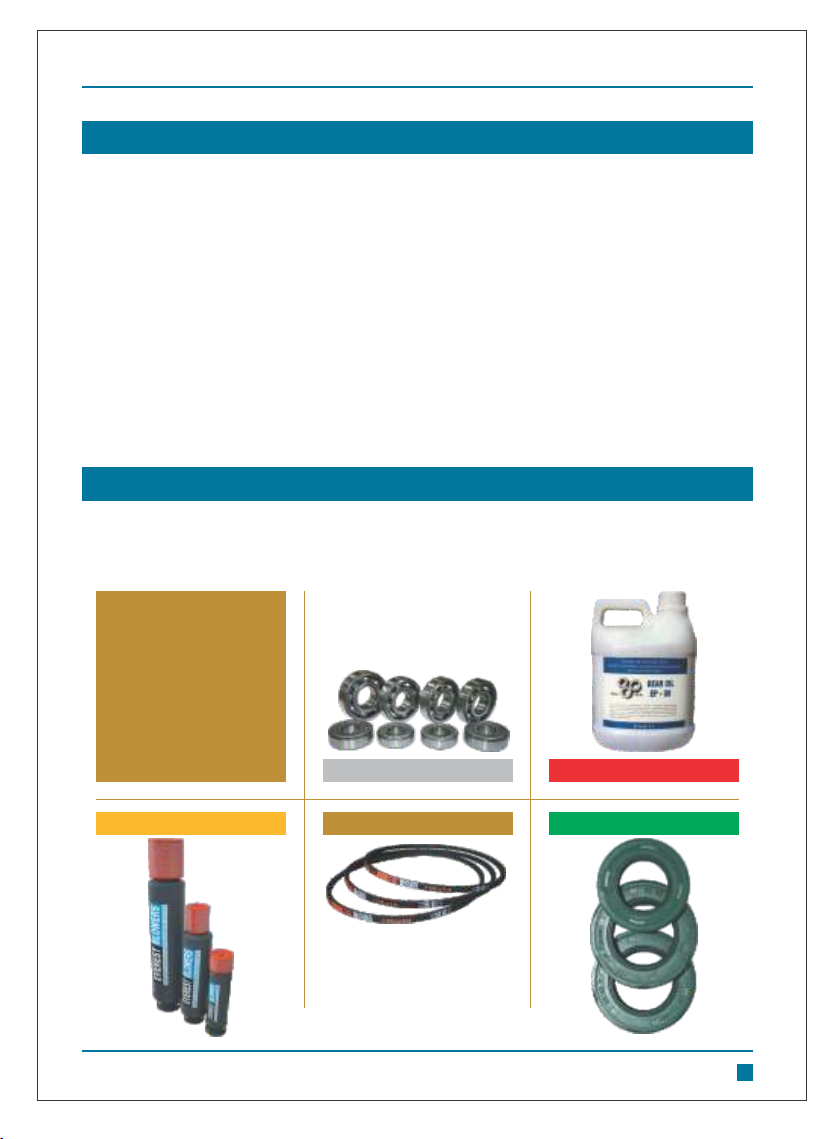
BEARINGS
VEE BELTS
SILENCERS & FILTERS
GEAR OIL
SEALS
Everest
Spares and
Consumables
SPARES & CONSUMABLES
Recommended Spares: Bearings, lip seals/labyrinth seals/piston rings, & gaskets.
Consumables such as filters, vee-belts, lubricating oil & grease do not form a part of spares.

Instruction Manual
© Everest Blowers 2
www.everestblowers.com 19
ORIENTATION OF BLOWERS
All blower models are available in specific orientations (based on direction of flow of air/gas).
Broadly they may be Horizontal flow, Vertical flow or Right Angle Flow.
Suction Discharge
HORIZONTAL FLOW ORIENTATION
VERTICAL FLOW ORIENTATION
Suction
Discharge
RIGHT ANGLE FLOW ORIENTATION
Discharge
Suction
This manual suits for next models
2
Table of contents
Popular Blower manuals by other brands

Lithium Earthwise
Lithium Earthwise LB20024 Operator's manual

EINHELL
EINHELL GE-CL 36 Li E Original operating instructions

EINHELL
EINHELL VENTURRO 18/210 operating instructions

Troy-Bilt
Troy-Bilt 657 Operator's manual

Weed Eater
Weed Eater VS2000BV instruction manual

KRAUSMANN
KRAUSMANN U37020-00 Operation manual


