Everest EGC 50 A User manual

VALID FOR UNITS PRODUCED SINCE SEPTEMBER/2015
ICE CUBE MACHINES
EGC 50 A EGC 75 A EGC 100 A / 150 A EGC 150 MA
EGC 150 MA / 140 EGC 150 MA / 250 EGC 300 MA / 250
SINCE 1966
TECHNICAL MANUAL
MARÇO/2017 REV.170331

INDEX
INTRODUCTION/TECHNICAL FEATURES................................................................................................................
MODELS AND POSSIBLE SETTINGS.......................................................................................................................
IMPORTANT INFORMATION..................................................................................................................................
EQUIPMENT INSTALLATION.................................................................................................................................
TYPICAL INSTALLATION DIAGRAM.......................................................................................................................
MAIN COMPONENTS..........................................................................................................................................
OPERATING PRINCIPLE.........................................................................................................................................
1 - CLEANING CYCLE............................................................................................................................................
2 - ICE FORMATION CYCLE...................................................................................................................................
3 - ICE FORMATION CYCLE...................................................................................................................................
4 - OPERATION OF THE TANK THERMOSTAT..........................................................................................................
SCHEDULED MAINTENANCE.................................................................................................................................
NAME OF MAIN COMPONENTS...........................................................................................................................
OVERVIEW EGC-50A...........................................................................................................................................
OVERVIEW EGC-75A, EGC-100A AND EGC-150A.................................................................................................
OVERVIEW EGC-150MA......................................................................................................................................
COOLING SYSTEM EGC-50A, EGC-75A, EGC-100A AND EGC-150A......................................................................
COOLING SYSTEM EGC-150MA...........................................................................................................................
ELECTRICAL ELECTRONIC PART............................................................................................................................
TROUGH DISPLACEMENT SYSTEM.......................................................................................................................
DISPLACEMENT ARM ASSEMBLY.........................................................................................................................
WIRING DIAGRAM EGC-50A, EGC-75A, EGC-100A-220V.....................................................................................
ELECTRICAL DIAGRAM EGC-150A-220V..............................................................................................................
ELECTRICAL DIAGRAM EGC-150MA-220V...........................................................................................................
WIRING DIAGRAM EGC-50A, EGC-75A, EGC-100A-127V.....................................................................................
WIRING DIAGRAM FOR TECUMSEH COMPRESSORS.............................................................................................
WIRING DIAGRAM FOR TECUMSEH COMPRESSORS.............................................................................................
1 - EQUIPMENT FAILURE MANAGEMENT...............................................................................................................
1 - SYMPTOM: WATER SHORTAGE OR LOW WATER FLOW RATE.............................................................................
2 - SYMPTOM: PLASTIC TROUGH DO NOT DESCENDS...........................................................................................
3 - SYMPTOM: TROUGH (35) DESCENDS BUT DOES NOT REACH THE LOWEST POINT..............................................
4 - SYMPTOM: BY-PASS CYCLE OVER 2 MINUTES...................................................................................................
5 - SYMPTOM: TROUGH (35) IS SUSPENDED, BUT DOES NOT REACH THE LOWEST POINT.......................................
6 - SYMPTOM: TROUGH (35) IS SUSPENDED, BUT DOES NOT REACH THE HIGHEST POINT......................................
7 - SYMPTOM: THROUGHOUT THE WATER INLET, THE TROUGH (35) DOES NOT STAY AT THE HIGHEST POINT..........
2 - ANALYSIS OF DEFECTS.....................................................................................................................................
2.1 - MACHINE DOES NOT WORK.........................................................................................................................
2.2 - WATER SHORTAGE OR LOW WATER FLOW....................................................................................................
2.3 - WATER TROUGH GOES UP AND DOWN CONTINUOUSLY...............................................................................
2.4 - CONTINUOUS ENTRANCE OF WATER IN THE TROUGH...................................................................................
2.5 - LOW ICE PRODUCTION.................................................................................................................................
2.6 - MACHINE WORKING BUT DOES NOT PRODUCE ICE.......................................................................................
2.7 - CUBES DO NOT DETACH FROM THE EVAPORATOR ........................................................................................
3 - ADJUSTMENT AND REPLACEMENT OF MAIN COMPONENTS.............................................................................
3.1- DISPLACEMENT SYSTEM AND TROUGH.........................................................................................................
3.2 - ADJUSTMENT OF WATER LEVEL AND HEIGHT OF ICE.....................................................................................
3.3 - AXIS UNSETTLED.........................................................................................................................................
3.4 - CIRCUIT BOARD...........................................................................................................................................
3.4 - CIRCUIT BOARD DOES NOT CONTROL ANY COMPONENT..............................................................................
3.4.1 A - COMPONENTS THAT SENDS INFORMATION TO THE BOARD....................................................................
3.4.1 B- COMPONENTS CONTROLLED BY THE ELECTRONIC BOARD.......................................................................
3.5 - INOPERATIVE WATER VALVE.........................................................................................................................
3.6 - GAS CHARGE/REPLACEMENT OF THE COOLING COMPRESSOR......................................................................
2
4
5
5
6
7
8
8
8
8
8
9
10
11
12
13
14
14
15
16
16
17
17
17
18
18
18
19
20
21
21
22
22
23
23
24
24
24
25
25
25
26
26
26
27
27
28
29
30
30
31
32
33
DEAR USER:
Everest Refrigeração Indústria e Comércio Ltda, congratulates you for choosing to purchase your
Automatic Ice Cube Machine. In our industry, everything was done to make sure that your
machine will have the best performance for many years to come. Your collaboration is required by,
first reading this manual carefully, and then using it as recommended below.
In all of the AUTOMATIC ICE CUBE MACHINE models, improvements were made in mechanics
and electronics that resulted in a 40% reduction in the consumption of waste water,
improvements on the physical appearance of the ice and the ability to identify anomalies in
equipment operation, working to correct and/or protect the equipment, preventing damage to
the main components.
INTRODUCTION
2
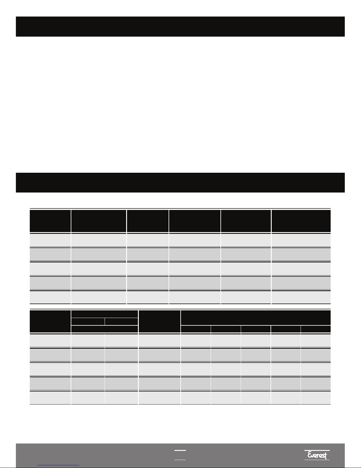
GENERAL TECHNICAL CHARACTERISTICS
MODELO DIMENSÕES
(A/L/P) cm
COMPRESSOR
(HP NOMINAL)
MASSA DO
APARELHO GÁS
(HFC) MASSA DO GÁS
REFRIGERANTE
EGC
75A
EGC
150A 111 x 89 x 54 78 kg 2 x 1/3 R-134a 2 x 225 g
MODEL DIMENSIONS
(A/L/P) cm
COMPRESSOR
(NOMINAL HP)
DEVICE
WEIGHT GAS
(HFC)
WEIGHT OF
REFRIGERANT GAS
EGC
50A
EGC
75A
EGC
100A
EGC
150A
EGC
150MA
61 x 45 x 54
111 x 57 x 54
111 x 89 x 54
111 x 89 x 54
63 x 93 x 35
32 kg
49 kg
61 kg
76 kg
60 kg
1/4
1/3
1/3
2 x 1/3
2 x 1/3
R-134a
R-134a
R-134a
R-134a
R-134a
175 g
220 g
350 g
2 x 225 g
2 x 220 g
MODELO DIMENSÕES
(A/L/P) cm
COMPRESSOR
(HP NOMINAL)
MASSA DO
APARELHO GÁS
(HFC) MASSA DO GÁS
REFRIGERANTE
EGC
75A
EGC
150A 111 x 89 x 54 78 kg 2 x 1/3 R-134a 2 x 225 g
MODEL POWER
watts
PRODUCTION: kg/24hours
at room temperature
EGC
50A
EGC
75A
EGC
100A
EGC
150A
EGC
150MA
380
630
647
1256
1230
VOLTAGE
5.4 A
9.4 A
9.5 A
-
-
ELECTRICAL CURRENT
127V 220V
32ºC
2,7 A
4.7 A
4.6 A
9.3 A
9.3 A
27ºC22ºC 37ºC 42ºC
485052 42 36
7680
82 70 62
98
108114 84 70
152
160166 140 122
144
158
162 130 101
3
MODELO DIMENSÕES
(A/L/P) cm
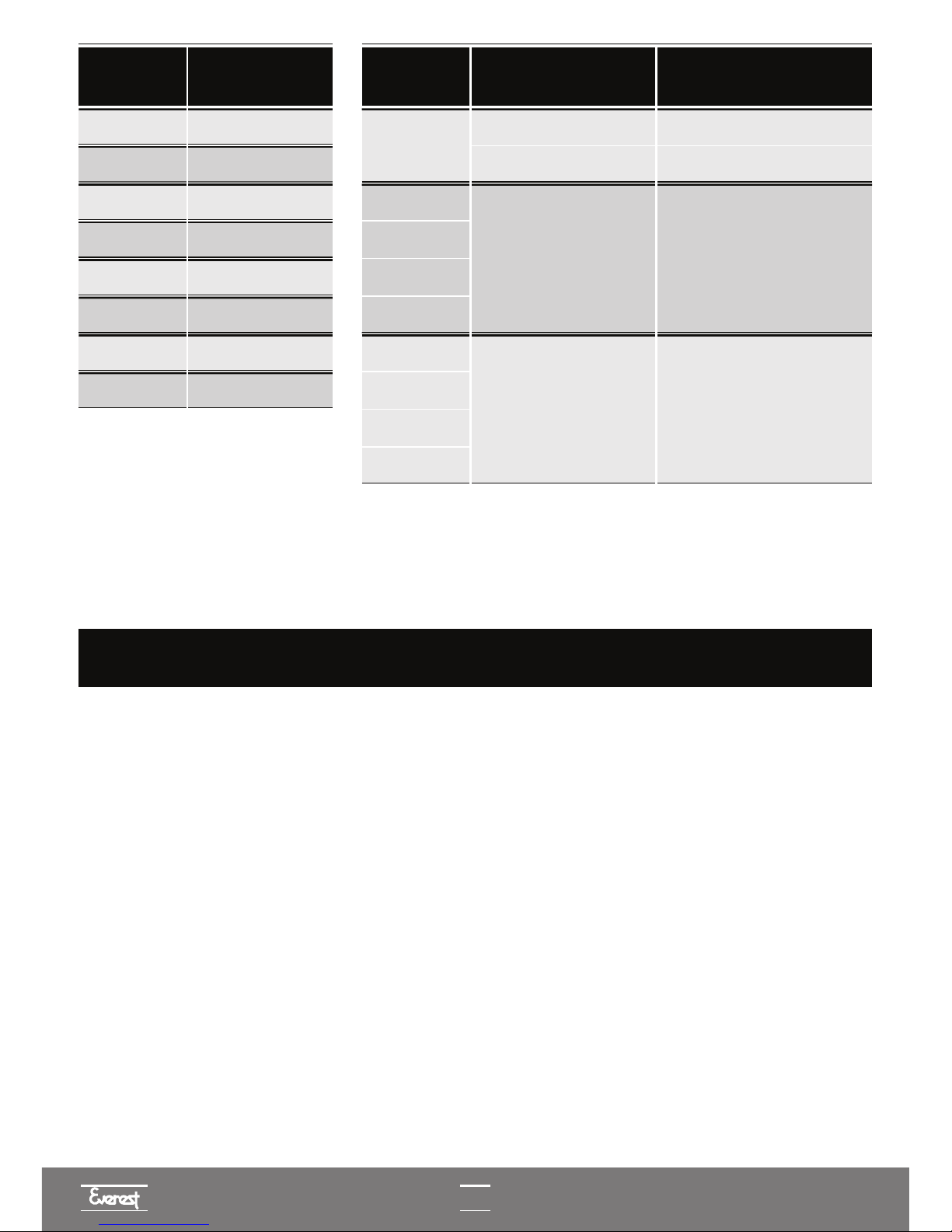
MODEL MIN. SECTION OF
THE WIRES (mm2)
EGC
50A - 127V
EGC
50A - 220V
EGC
75A - 127V
EGC
75A - 220V
EGC
100A - 127V
1,5
1,5
2,5
1,5
2,5
EGC
100A - 220V 1,5
EGC
150A - 220V 2,5
EGC
150MA - 220V 2,5
MODEL COMPRESSOR MODEL
EMBRACO FFI 12 HBX
EGC
75A
EGC
100A
EGC
150A
EGC
150MA
TECUMSEH AE4430Y (AE-540)
EMBRACO FFI 8.5 HBK
EGC
50A
TECUMSEH AE4450Y (AE-660)
EGC
75A
EGC
100A
EGC
150A
EGC
150MA
• DEVICE FOR INTERNAL USE (IPX0).
• SUBTROPICAL CLASS DEVICE (CLASS ST)
On the production table, the water inlet temperature should be regarded as 5°C lower than
the room temperature.
EGC 150 MA / 140 EGC 150 MA / 250 EGC 300 MA / 250
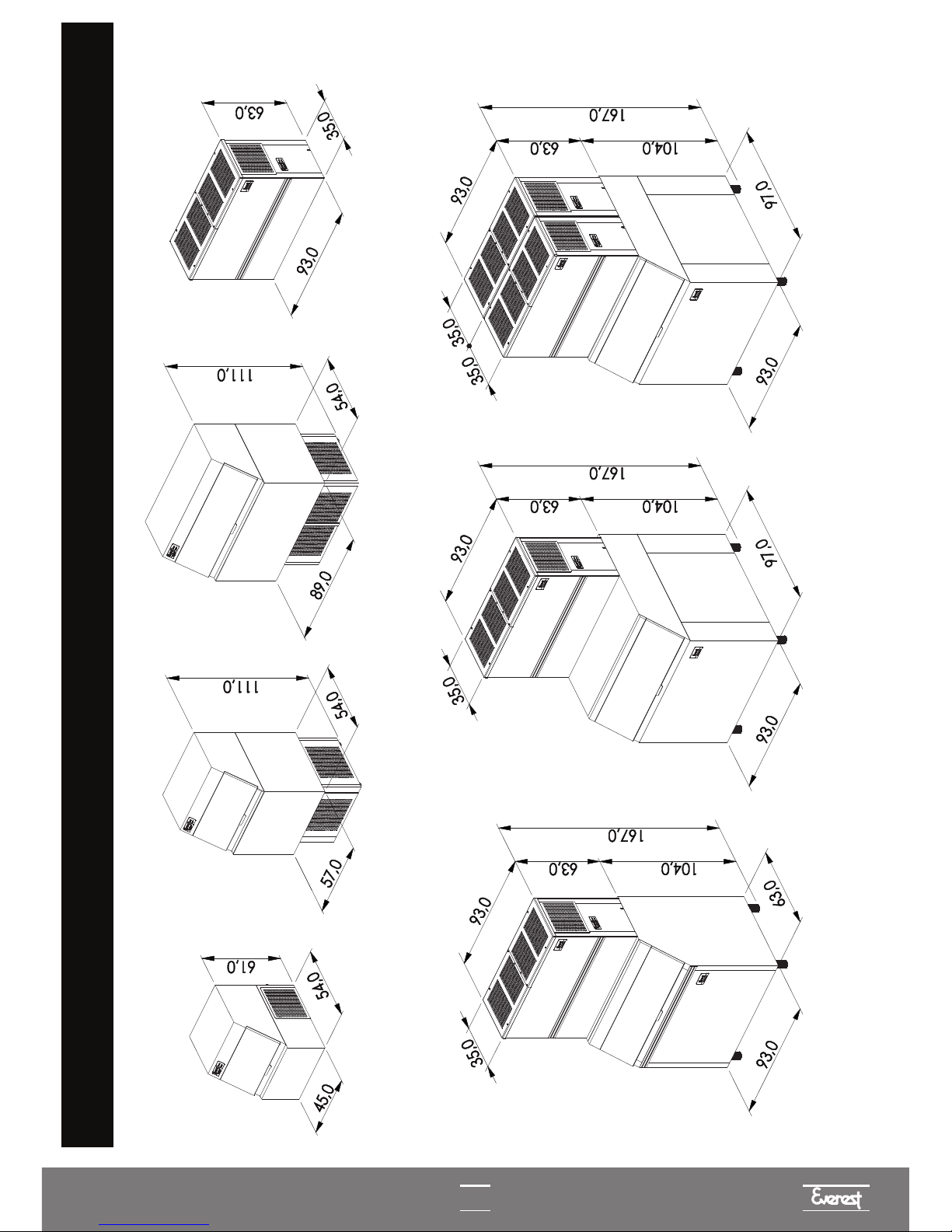
MODELS AND POSSIBLE CONFIGURATIONS
4
EGC 75 A
EGC 100 A / 150 A
EGC 150 MAEGC 50 A
5
I
I
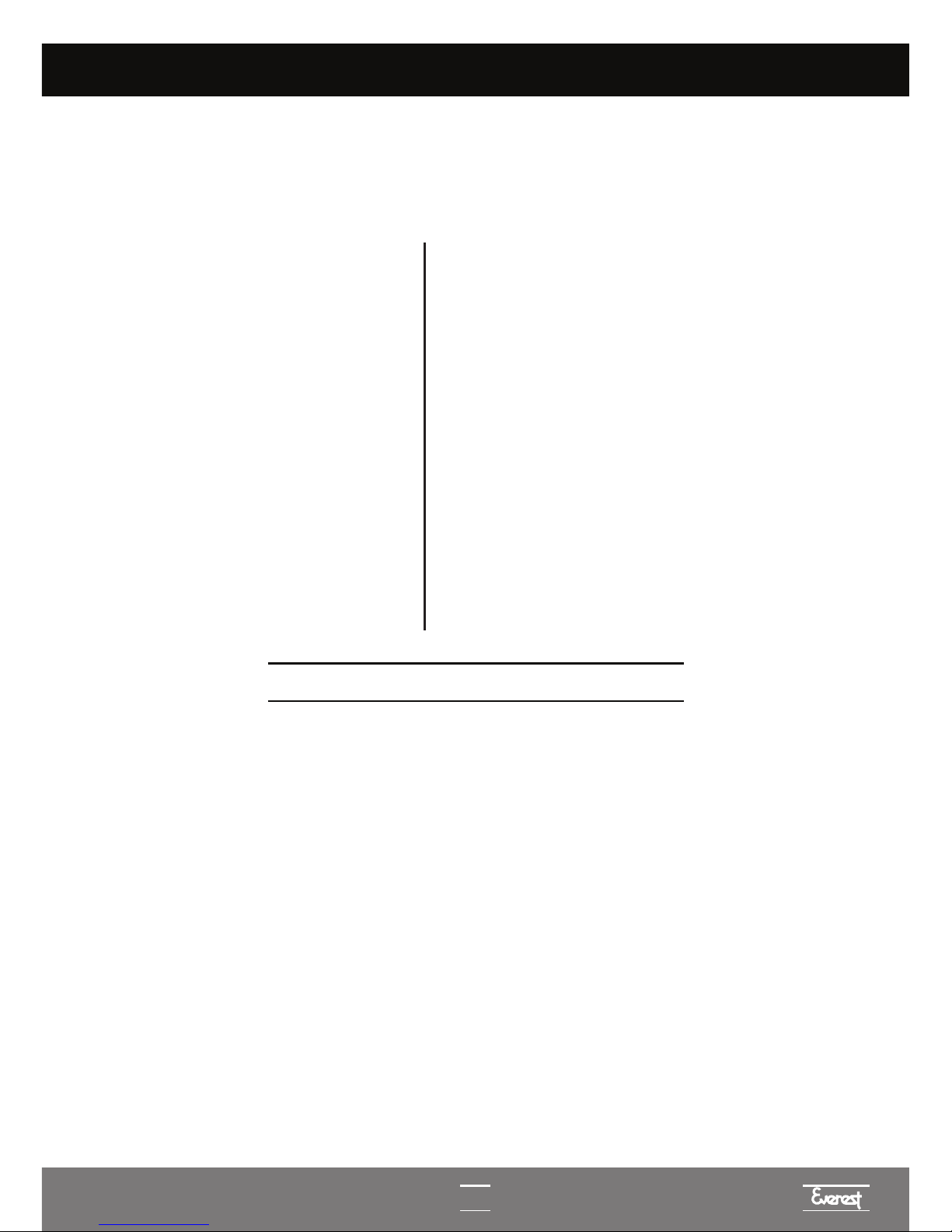
IMPORTANT INFORMATION
Carefully observe the following items upon
equipment receipt:
A • Check for possible damage resulting from
transportation and, should you find any irregularities,
contact your dealer immediately.
B • The water filter, water inlet hose, plastic scoop,
warranty certificate and technical support network can be
found inside the ice storage bin. Notice that the water
inlet hose has a connection that is curved at 90°. This
connection is specific for the machine's water solenoid
valve (63).
C • In model EGC 150M, the items above are inside the
machine.
D • The parts and accessories of the ice bin are inside it.
Warning: Only connect the equipment to the drinking
water supply.
The removable hose set provided with the
ice machine must be connected to the water
network. It is forbidden to reuse the hose or
use a hose from a washing machine.
Do not store explosive substances, such as
aerosol cans containing a flammable
propellant in this device.
This device is dedicated to domestic
use, such as:
• Kitchen areas in stores, offices and other
work environments;
• Farm houses, hotels, motels and other
types of residential environments;
• Environments like hostels;
• Caterers and other non-retail applications.
EQUIPMENT INSTALLATION
Observe the following items carefully when installing the equipment:
A • Check if the place has drinking water.
B • The equipment must be leveled.
C • Check if the fan blades (24) turn freely.
D • Make sure the voltage of the power supply network is in accordance with the one identified on the power
cord of the equipment.
For 127V from 103V to 135V
For 220V from 198V to 242V
E • The plug used allows your equipment to be grounded, thus avoiding the occurrence of electrical
discharges. If the electrical installation (NBR14136) is not in compliance, the installation will be
carried at the user's own risk.
F • The water supply network shall be provided with a specific valve to use the machine. The diameter of the
pipes should be at least V2"(12.7mm), with maximum pressure recommended for use of 0.392 MPa
(4.0kgf/cm2) and the minimum pressure of 0.029 MPa (0.3kgf/cm2).
G • The water is removed using a flexible hose, which should be placed in the sewage entry point below the
machine level, and with the capacity of absorbing at least 3 liters per minute. In the EGC-150MA model, the
sewage entry point should be below the tank level.
This equipment is not intended for use by people - including children - with reduced physical, sensory or
mental capacity, or by people with lack of experience and knowledge, unless they have received instructions
regarding the use of the equipment or they are under the supervision of a person responsible for their safety. It
is recommended that children be supervised to ensure that they do not play with the equipment.

6
I
TYPICAL INSTALLATION DIAGRAM
1) Ice cube machine.
2) Female electrical outlet.
3) Water supply valve.
4) Water filter.
5) Hydraulic connection filter / water inlet hose.
6) Flexible water inlet hose.
7) Flexible water outlet hose (for sewage entry point).
Notes:
1 • Diagram for installer's guidance only.
2 • Items 2 and 3 of the installation diagram are not an integral part of the equipment.
3 • The buyer is responsible for installing the equipment.
4 • For the EGC-50A machines, provide a minimum space of 15cm at the sides, rear and top part for
ventilation.
5 • For the EGC-75A, EGC-100A, EGC-150A and EGC-150MA machines, provide a minimum space of
20cm on the sides and rear for ventilation.

7
I
A • Evaporator (20): Made of copper with nickel finishing, it has vertical cube makers around which
the ice cubes are formed.
B • Gear motor (60): It moves the plastic trough (35).
C • Micro gear motor (57): It moves the finned axis in order to stir the water, improving the ice
quality. Triggers the end of cycle microswitch.
D • End of cycle microswitch (59): It sends a signal to the circuit board signaling the end of the ice
formation cycle.
E • Upper reed switch (54): Positions the trough at the highest point.
F • Lower reed switch (58): Positions the trough at the lowest point.
G • Mobile water sensor (55): Determines the water level, which defines the ice cube's height.
H • Tank's thermostat (61): Turns the machine off when the tank is filled with ice and turns it on again
when the ice is consumed.
I • Gas solenoid valve (28): Allows the hot coolant gas to enter the evaporator directly, causing the ice
to detach therefrom.
J • Water solenoid valve (63): Its function is to fill the water trough at the beginning of each cycle.
K • Plastic Trough (35): Container for water storage where the ice cubes are formed.
L • Micro switch of the fan (46): Turn off the fan when the trough is lowered to perform by pass,
improving the detachment of ice cubes.
M • Compressor (23): Compresses the refrigerant gas, which is designed to work under medium and
high return pressure, necessary characteristics for an ice machine.
N • Circuit board (62): Receives information from the water level sensor, end of cycle microswitch,
upper reed switch, lower reed switch and it also controls the operation of the water solenoid valve, gear
motor, micro gear motor and gas solenoid valve. Sends the signal to the LEDs in case of necessary
maintenance and water shortages.
O • Fan (24): Main component to perform condensation.
MAIN COMPONENTS

OPERATING PRINCIPLES
I
1 - CLEANING CYCLE
I
1.2 - Cleaning of the Plastic Trough (35).
The plastic trough (35) will reach its maximum lower position to discharge the water from the last cycle which was
interrupted by the shutdown of the Machine. This cleaning cycle is necessary due to safety and hygiene reasons,
because we could not quantify the time that the Ice Machine is turned off, with water inside the plastic trough (35).
1.1 - Initialization
Every time the machine is energized (connected to the power grid, switched on again by the tank's thermostat
(61) or after a power surge), the cleaning cycle for the plastic trough (35) and evaporator (20) starts up. The
signaling LEDs - LD1 (maintenance), LD2 (water shortage) - for the circuit board (62) and the LED board (68),
light up for a period of 02 seconds, in order to inform the start-up of the system's operation.
2 - ICE FORMATION CYCLE
2.1 - Formation
After the cleaning cycle, the plastic trough (35) returns to the highest position, the circuit board (62) switches on
the water valve (63) to let water in the the plastic trough (35), the mobile water sensor (55) indicates to the
circuit board (62) when the water level of the plastic trough (35) touches it, and switches off the water valve (63).
With the cooling system in operation, the formation of ice around the cube makers in the evaporator begins (20),
such cubes will grow to a thickness that obstructs the passage of the plastic fins (29) which rotate continuously.
3 - ICE DETACHMENT CYCLE
The purpose of the tank thermostat (61), whose bulb is fixed below the equipment's water draining tray, is to
switch the equipment off when it is filled with ice and turn it back on when the ice level in the tank (6) decreases.
In the EGC-50A model, the thermostat bulb is fixed in the tank. (6)
3.1 - “Quick Stop”
After 45 seconds, the circuit board (62), switches on the gear motor (60) to lower the plastic trough (35) and
discharge the residual water from the ice formation cycle. In this lowering interval, the plastic trough (35) will
perform a temporary stop, this action avoids the residual water - which is close to zero degrees - from reaching
the tank thermostat (61) and switching off the Ice Machine unnecessarily.
4 - OPERATION OF THE TANK THERMOSTAT
8
1.3 - Evaporator Cleaning (20).
With the plastic trough (35) at the lowest position, the gas solenoid valve (28) is activated for 45 seconds, cleaning
the evaporator from ice cubes.
3.2 - Ice detachment cycle.
With the plastic trough (35) positioned at the lowest point, the by-pass cycle begins. The circuit board (62)
switches on the gas solenoid valve (28), which allows the hot gas to enter directly into the evaporator (20),
detaching the ice cubes. After 45 seconds of By Pass, the circuit board (62) switches on the micro gear box (57)
for 5 seconds and checks whether the finned axis (50) is still blocked by any ice cube. If the finned axis (50) is
blocked, the by-pass time is increased by 5 more seconds, as often as needed, for up to 2 minutes. In case it is
unblocked, the circuit board (62) switches off the gas solenoid valve (28) and switches on the motor gear (60),
returning the plastic trough (35) to the highest point and restarting a new ice formation cycle.
2.2 - Growing cycle
When the ice cubes grow up to a thickness that prevents the rotation of the plastic fins (57), the micro gear
motor coupled to the finned axis (50) activates the end of cycle micro switch (59), indicating to the circuit board
(62) that the ice formation cycle is completed. In this moment, the circuit board (62), switches off the micro gear
motor (57). The system will wait for 10 seconds with the plastic trough (35) on the highest position, allowing
the residual water from the ice formation cycle to be used, increasing the volume of ice cubes and reducing the
volume of water discharged.
1.4 - The fan (24).
The fan (24) is activated through the micro switch (46). The micro switch (46) is fixated on the left panel of the
cylinder head (44), in a way that its rod is activated by the plastic trough (35). When the trough is lowered, the micro
switch (46) opens and it switches off the fan (24). This action assists the detachment of the ice cubes. When the
BYPASS is finished, the plastic trough (35) is elevated, the micro switch (46) is closed and the fan is switched on (24)

9
SCHEDULED MAINTENANCE
4 • The following items must be checked during scheduled maintenance:
A • Check and clean the screen of the water solenoid (63) valve.
B • Clean the gas condenser (25).
C • Clean the plastic trough (35) and the trough's water sensors (55 and 67).
D • Clean the ice tank (6), checking for incrustation or blocking, both in the draining tray and the tank's drain (6).
E • Check if the machine is leveled.
F • Check if the fan blade (24) rotates freely and if it is well balanced (there should be no vibrations when it is
operating).
G • Check if the finned axis (50) rotates freely , also observing gaps in the finned axis' bearings (41). (see p. 30
item 3.3)
H • Check the water level in the plastic trough (35). The level determines the size of the ice cubes. If you want to
increase or decrease cube size, verify item 3, sub-item 3.2, failure management, p. 30 (Adjustment of water level
and ice cube height) contained in this manual.
I • Check the wear of the sintered bronze bushings (32) on the plastic trough (35).
J • Check the filtering cartridge. When replaced, it should be by the same or similar model, in order to reduce the
corrosive effect of chlorine on the stainless steel, as well as ensuring the best quality of ice produced.
Before starting maintenance, unplug the machine and remove the machine's cover (1), except for
the EGC-150MA model.
For the EGC-150MA model: Remove the right side plate (16), loosen the fixation screws, open the frontal lid or
the right side plate (16).
1 • Maintenance and cleaning schedules are suggested to keep your equipment in good condition. Cleaning
varies especially depending on the location of the installation, water conditions and the volume of ice produced.
We recommend that maintenance be carried out every 6 months.
2 • The replacement of the power cord should only be carried out by the manufacturer. Authorized Technical
Assistance or a qualified professional, in order to avoid risks for the user and damage to your equipment.
3 • Filtering Cartridge Replacement.
Your equipment is supplied with an activated carbon filter. The service life of the filter is 6 months and it
depends on the quantity and quality of water passing through the filter cartridge, which aims at retaining
impurities, reducing chlorine, strange odors and flavors in the water, as well as minimizing the corrosive
effect of chlorine on the stainless steel. The filtering cartridge, which is located inside the filter, does not
allow cleaning after saturation, so it should be changed.

10
COVER
FRONT COVER EGC-50Atf 5A/100A/150A
PLASTIC GRATING EGC-50A/75A/100A/150MA
WATER COLLECTOR OF THE EGC-50A TANK
ICE TANK HOUSING
EGC-50A COOLING UNIT BASE
REAR GRATING EGC-A
COVER'S HINGE
WHEEL
EGC-75A/100A/150A COOLING BASE
EGC-75A/100A/150A COLUMN
EGC-150MA BACK PLATE
BACK PLATE INSULATION EGC-150MA
UPPER GRATING OF THE EGC-150MA
RIGHT SIDE PLATE EGC-150MA
EGC-150MA FRONT PLATE
EGC-150MA STRUCTURE
EGC-150MA LEFT SIDE PLATE
EVAPORATOR
TROUGH STOPPER
EGC-100A/EGC-150A/EGC-150MA
SUPPORT BRACKET OF THE EVAPORATOR
FAN
COMPRESSOR
CONDENSER
GAS FILTER
CAPILLARY TUBE
GAS SOLENOID VALVE (ASSEMBLY)
PLASTIC FIN
PLASTIC SPACER
SPRING
SINTERED BRONZE BUSHING
LOWER MAGNET
PLASTIC TROUGH
RIGHT PANEL CYLINDER HEAD
UPPER REED SWITCH SUPPORT
EVAPORATOR PROTECTION PLATE
LOWERING ICE GRATING EGC-75A EGC-100AE EGC-150A
NAME OF MAIN COMPONENTS
1
2
3
4
5
6
7
8
9
10
11
12
13
14
15
16
17
18
19
20
21
22
24
23
25
26
27
28
29
30
31
32
33
35
37
34
36
38
40
41
42
43
44
45
46
47
48
49
50
51
52
53
54
55
56
57
58
59
60
61
62
63
64
65
66
67
68
69
70
71
72
73
74
76
75
PLASTIC TROUGH SUPPORT ASSEMBLY
FINNED AXIS' BEARING
LEVER-ARM REDUCER
SPRING PIN
LEFT PANEL OF CYLINDER HEAD
MICRO GEAR MOTOR CONNECTION BUSHING
FAN MICROSWITCH
MICROSWITCH PLASTIC SUPPORT
MOBILE ARM
SPACER TUBE OF THE EGC-A ARM
FINNED AXIS
BY-PASS OF GAS SOLENOID COIL
BY-PASS OF GAS VALVE HOUSING
UPPER REED SWITCH
MOBILE WATER SENSOR
WATER LEVEL SENSOR SUPPORT
MICRO GEAR MOTOR
LOWER REED SWITCH
END OF CYCLE MICROSWITCH
GEAR MOTOR
TANK THERMOSTAT
CIRCUIT BOARD
WATER SOLENOID VALVE
TRANSFORMER 127/220V - 80VA
FIXED WATER SENSOR
PANEL SUPPORT AXIS
REAR CABINET COVER
FRONT LABEL
SPRING ASSEMBLY
FRONTAL GRATING EGC-A
REAR GRATING EGC-A
SIDE GRATING EGC-75A/100A/150A
RIGHT/LEFT SIDE PROTECTION PLATE
UPPER MAGNET
39
77
78
TROUGH SUPPORT RAIL
FUSE HOLDER
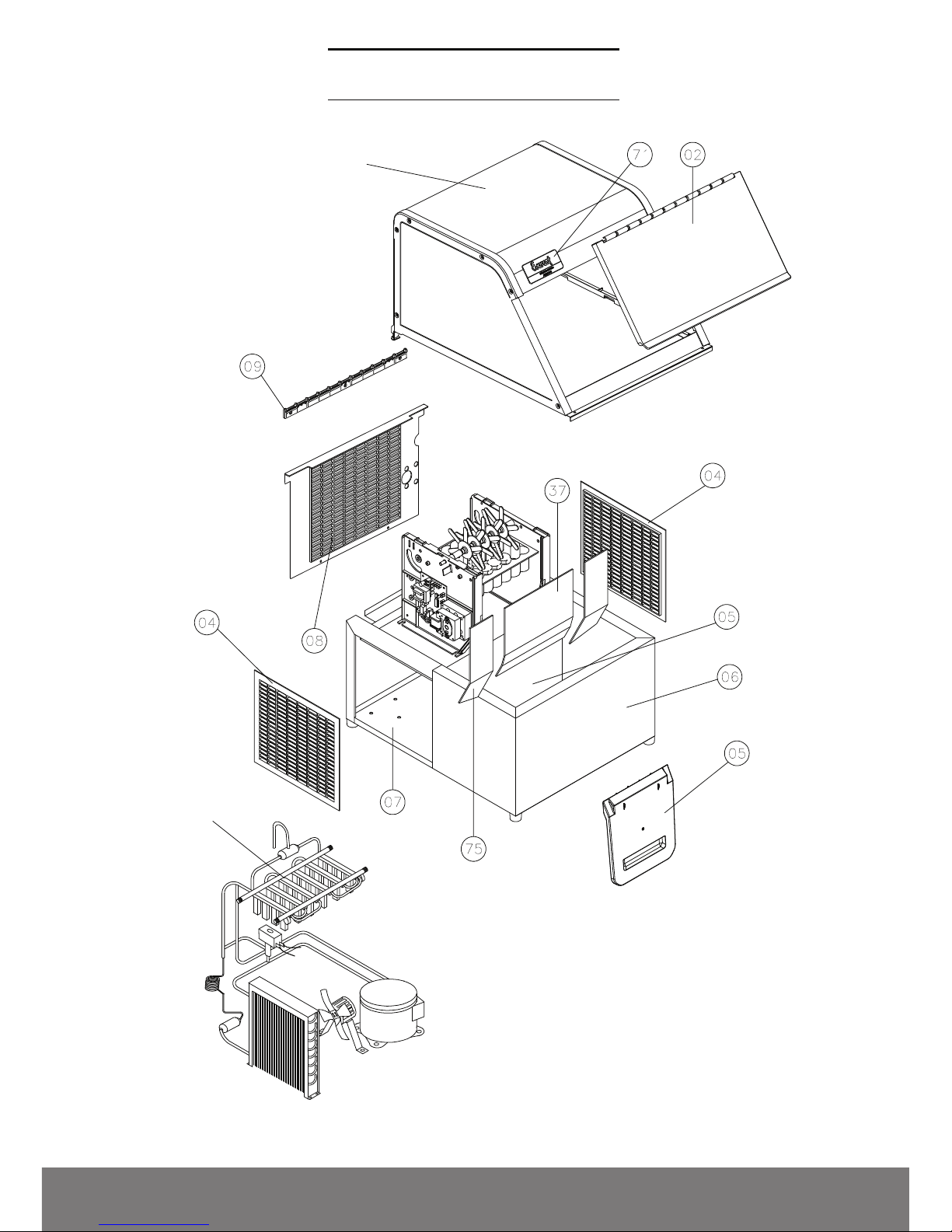
OVERVIEW EGC-50A
COVER
COOLING SYSTEM

OVERVIEW EGC-75A, EGC-100A AND EGC-150A
In the EGC-150A model, there are two compressors and two fans.
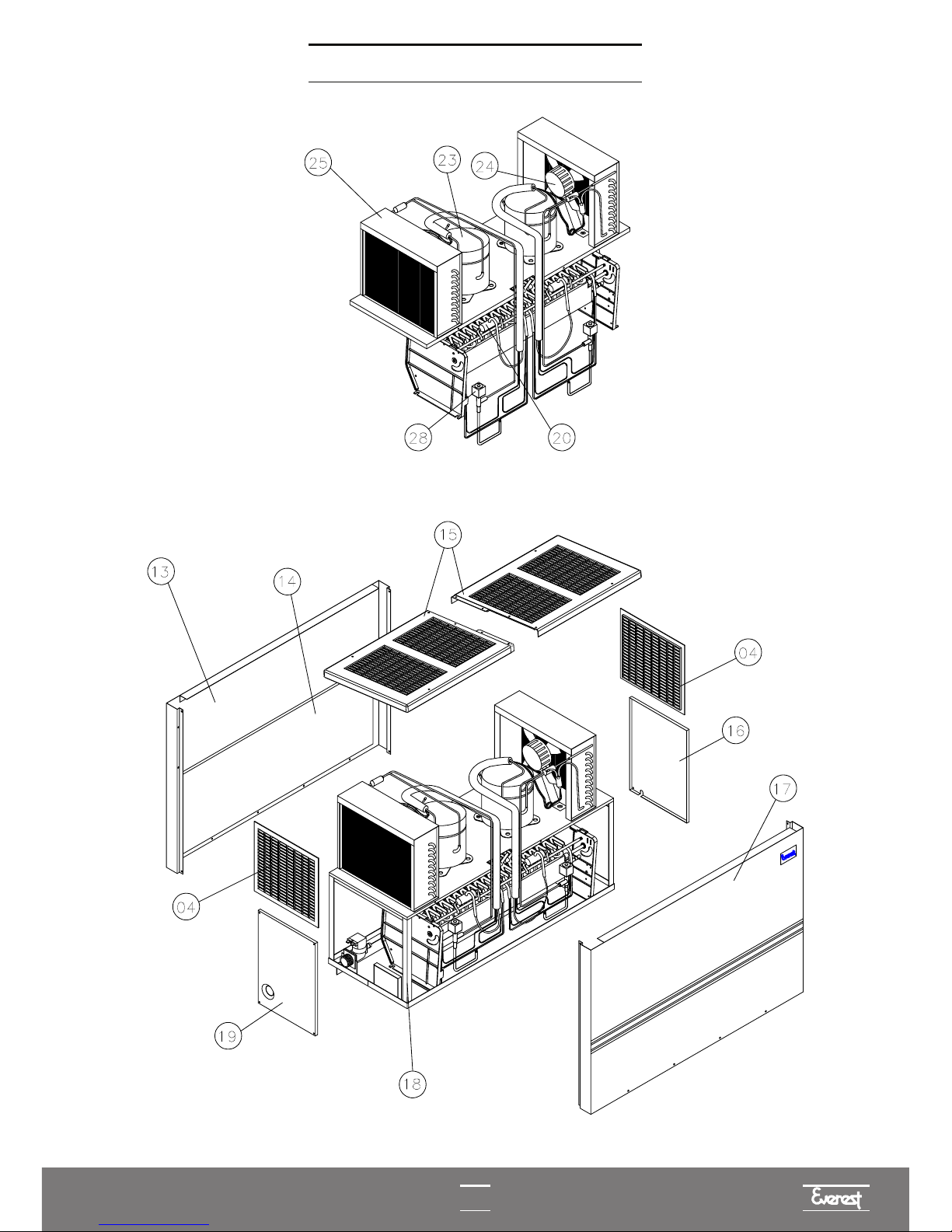
13
I
OVERVIEW EGC-150MA
I

14
COOLING SYSTEM
EGC-50A, EGC-75A, EGC-100A AND EGC-150A
I
COOLING SYSTEM EGC-150MA
I
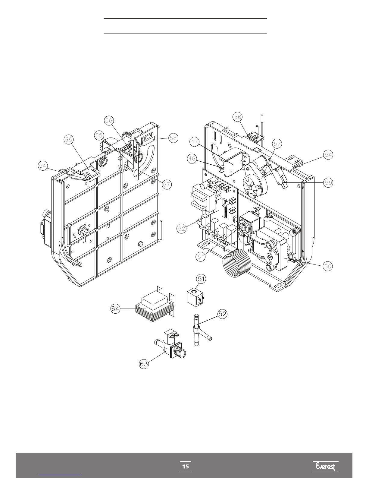
ELECTRICAL/ELECTRONIC PART
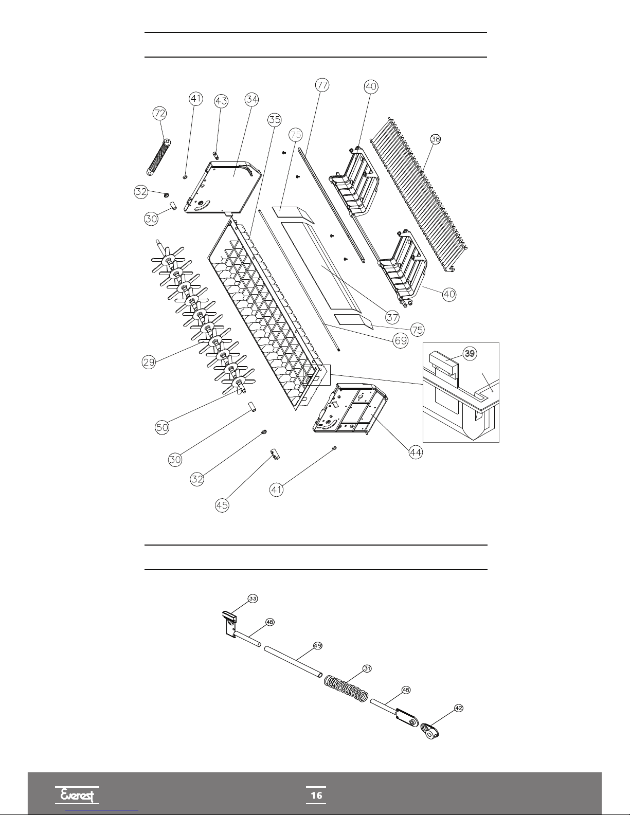
TROUGH DISPLACEMENT SYSTEM
DISPLACEMENT ARM ASSEMBLY
TROUGH

ELETRICAL DIAGRAM EGC-50A, EGC-75A, EGC-100A - 127V
ELETRICAL DIAGRAM EGC-50A, EGC-75A, EGC-100A - 220V
ELETRICAL DIAGRAM EGC-150A, EGC-150MA - 127V
FAN
FAN MICROSWITCH
TRANSFORMER
THERMAL
PROTECTOR
PLUG
FUSE HOLDER
TANK
THERMOSTAT
CIRCUIT
BOARD
MICRO GEAR MOTOR
END OF CYCLE
MICROSWITCH
REDUCER
GAS VALVE
WATER VALVE
WATER
LEVEL
SENSOR
RELAY
START-UP
CAPACITOR
START-UP
CAPACITOR
FAN
THERMAL
PROTECTOR WATER
LEVEL
SENSOR
MICRO GEAR MOTOR
END OF CYCLE
MICROSWITCH
CIRCUIT
BOARD
REDUCER
GAS VALVE
WATER VALVE
FAN MICROSWITCH
FUSE HOLDER
TANK
THERMOSTAT
RELAY
FAN THERMAL
PROTECTOR
FAN
START-UP
CAPACITOR
THERMAL
PROTECTOR
START-UP
CAPACITOR RELAY
WATER
LEVEL
SENSOR
CIRCUIT
BOARD
MICRO GEAR MOTOR
END OF CYCLE
MICROSWITCH
GAS VALVE
GAS VALVE
WATER VALVE
TANK
THERMOSTAT
FUSE HOLDER
TRANSFORMER
FAN
MICROSWITCH
REDUCER

18
ELECTRICAL DIAGRAM EGC-150A, EGC-150MA - 220V
ELECTRICAL DIAGRAM FOR TECUMSEH COMPRESSORS
ELECTRICAL DIAGRAM FOR EMBRACO COMPRESSORS
C OF COMPROSSOR
MODEL FFI-12HBX
RELAY START-UP
CAPACITOR
PHASE
PHASE
THERMAL PROTECTOR
PHASE
THERMAL PROTECTOR
PHASE
START-UP
CAPACITOR
RELAY
MODEL AE 4450 Y
THERMAL
PROTECTOR
CIRCUIT
BOARD
MICRO GEAR MOTOR
END OF CYCLE
MICROSWITCH
REDUCER
GAS VALVE
WATER VALVE
WATER
LEVEL
SENSOR
GAS VALVE
THERMAL
PROTECTOR
START-UP
CAPACITOR
START-UP
CAPACITOR
FAN MICROSWITCH
FAN
FAN
RELAY
TANK
THERMOSTAT
FUSE HOLDER

19
EQUIPMENT FAILURE MANAGEMENT
The circuit board (62) is equipped with a program that monitors the operation of the ice machine.
When there is an anomaly in this function, it controls the main components (gear motor (60), micro
gear motor (57), gas solenoid valve (28) and water solenoid valve (63)), in order to resolve the
aforementioned anomaly or protect the equipment in general. Read carefully the items below
related to equipment failure and its probable causes.
This manual suits for next models
6
Table of contents
Popular Ice Maker manuals by other brands


U-Line
U-Line UMCR014-SC01A User guide & service manual

Scotsman
Scotsman Prodigy ELITE MC222 ECC Installation and user manual

Sub-Zero
Sub-Zero Undercounter Ice Machine Installation & operation guide

ITV ICE MAKERS
ITV ICE MAKERS MS Series maintenance

Diamond
Diamond ICE90MA Instructions for installation, use and maintenance manual

Hoshizaki
Hoshizaki KM-1601SRH parts list