EverExceed uXcel Series User manual

uXcel series charger
user manual
Everexceed Corporation

1
Thank you for using the products of EverExceed.
Please strictly follow all safety instructions and instructions in the manual before using the
machine. In the absence of complete reading. Please do not operate this machine until some
safety instructions and instructions have made.
Please take good care of this product manual so that you can check it later.
Due to the continuous updating of the technical system, some contents of this manual may
be changed, and The company reserves the right to improve the technology without prior
notice.
Please keep this manual to the end operator and maintenance personnel.
Safety Precautions
Please do not install, operate, maintain or examine the equipment before reading the
user manual, service materials carefully and using it correctly.
Danger!!
Incorrect operating may cause the hazardous situation which will result in death or
serious injury
Notice!!
Incorrect operating may cause the hazardous situation which will result in minor or
moderate injury, or direct economic loss, or hardware damage of equipment. Notice: the
matter of “notice” may also result in serious consequences depending on different
situation. Please follow the two precautions for they are important to the person
concerned.

2
Safety Instructions
1).Avoid electric shock
Danger!!
Please do not touch any part of the battery or the frame, electrolyte, cooling water of
the battery by hand when the equipment charging up the battery. Operator shall wear
insulative waterproof rubber shoes and gloves to operate the battery, or may result in
electric shock injury accident.
Please do not operate the equipment when opening the door of equipment, or may
touch the high voltage terminal and result in electric shock accident.
Keep the equipment off-position when connecting the battery, or may result in electric
shock or injury.
Please do not open the equipment when powering on or operating, or would get an
electric shock.
Please do not approach nearby ground when the equipment is on-position because in
the process of charging, the output positive and negative side would in high pressure
and the ground would have leakage current from the frame. The ground nearby would
in high pressure.
Please do not touch the DC output end in high pressure state, or may result in electric
shock.
When Wiring or examining, power shall be disconnected and 10 minutes later,
detecting the residual voltage disappearing by multimeter, or may result in electric
shock accident.
Please do not maintain the equipment when the DC output end still connecting the
battery even though the power is at a off-position state. Please maintain without
connecting the battery, or may result in electric shock accident for the battery voltage
attaches to the equipment through output cable and the equipment still in high
pressure.
The equipment shall use third-level or above grounding method.
Please do not change the fuse when charging with electricity, or may result in electric
shock.
Please do not change the fuse when the equipment outputting and connecting the
battery.
Please do not operate the switch by wet hand to avoid electric shock.
The operation including wiring and examination shall be conducted by professional
technician.
Please do not damage, stress, clamp or make the input and putout cable carry heavy
objects, or may result in electric shock.
The battery rack or frame shall use third-level or above grounding method.
3
2).Avoid fire
Caution!!
The equipment shall be installed in ventilated situation. Keep the around distance of the
equipment 0.5 meters or more and the top and bottom vent shall not be blocked by
objects. Do not install near the flammable and explosive objects, or may result in
Please disconnect the power supply wiring and output battery wiring when the
equipment breaking down. The keeping flowing high current may result in fire.
Please use the fuse of prescribed specification or with the same performance. Using the
fuse of different model or different performance may result in fire.
3).Avoid Injury
Caution!!
The voltage of each terminal shall be the regulated voltage to avoid bursting and
damaging
Always ensure that the output positive and negative poles of the equipment are
connecting correctly with the positive and negative pole of the battery to avoid bursting
and damaging the battery.
Do not touch the equipment when connecting or just disconnecting the power supply
for the temperature of the equipment is high which results in scalding.
The input and output cable shall be connected according to the user manual. Orit may
result in bursting and injuring accident.
4
Other Precautions
Please pay attention to the following precautions to avoid accident, injury and electric shock
etc.
1).Transition and Installation
Notice!!
Please use accurate lift appliance when transiting the product to avoid injuring.
Please make sure the place could stand the weight of the equipment to avoid injuring
resulted by the problem of weight.
Please do not operate when the equipment injuring or lacking components.
Please transit by the bottom other than by the lifting padeyes, or may result in
injuring or falling off.
Please check the left and right vent of the equipment not blocking by objects.
Please keep the screw, the debris of cable or other conductive body or oil
combustible out off the equipment.
Please use in the following conditions.
Conditions
Ambient temperature
-100C to 40℃no freezing
Ambient temperature
90%RH no condensation of moisture
Storage temperature
-20℃to 60℃
Environment
Indoor(no corrosive gas, combustible gas, oil
pollution)
Altitude
under 2km
2). Wiring
Notice!!
Please correctly connect the positive and negative poles to the battery. In corrective
connection may injury the battery.
Please correctly connect the input and output cable according to the requirement of
the following drawing.
3). Trial Run
Notice!!
Please trial run according to the operation specification.

5
4). Operation
Notice
Please operate according to the operation specification.
Please take relevant measures to radiate the equipment, or the equipment may be
overheating and damaged because of the increasing ambient temperature.
Please check the nominal parameter values of the equipment when changing the
trigger board or touch panel. The mismatched nominal parameter could result in
abnormal charge and damage the battery.
Please trial run after maintaining the equipment.
The equipment unused for a long time shall keep away from dampness and keep in
seal. It must be checked and trial run before being used.
Power supply network shall have sufficient capacity.
5).Maintenance, check and components change
Notice!!
The setting parameters shall be the same with the nominal parameters of the
equipment when changing the touch panel.
The substituted components shall be the same prescribed specification or the same
performance.
The equipment shall be checked by professional.

6
Content
Safety Instructions..................................................................................................................... 2
Other Precautions ..................................................................................................................... 4
1. Overview................................................................................................................................ 7
2.Technical Parameters ............................................................................................................. 7
2.1. Product model and implication .................................................................................. 7
2.2. Working condition ...................................................................................................... 7
2.3. Performance parameters ........................................................................................... 8
3.Systematic principle ............................................................................................................... 9
3.1、System operating principle....................................................................................... 9
3.2、Circuit schematic diagram ........................................................................................ 9
4.Installation............................................................................................................................ 10
4.1. Safety precautions.................................................................................................... 10
4.2 Installation instructions............................................................................................. 10
5. Operating instructions......................................................................................................... 10
5.1 Panel display and description.................................................................................... 10
5.2 Touch panel operating............................................................................................... 12
5.3 Start-up debugging
...................................................................................................... 20
6. Trouble shooting
................................................................................................................... 21
7. Maintenance
......................................................................................................................... 22
7.1 Routine inspection and regular inspection
................................................................... 22
8.Warranty service
.................................................................................................................... 23
Attachment: control panel diagram and description.............................................................. 23

7
1. Overview
This manual makes comprehensive introduction of uXcel charger series, presenting the
working principle, systematic structure, usage and maintenance of the chargers in detail.
Hope it would be convenient for the user.
The product applies to the charging of all kinds of lead-acid batteries, alkaline batteries and
the power supply of DC load. The charger has reasonable and compact configuration. Under
the digital IC, the operation of the charger is convenient and reliable with the charging mode
of constant voltage, constant current and cycling. When operating, the operation panel
works out the procedure in advance. After working out, it starts charging. The whole
charging process is auto-complete. The important component, transformer, adopts
high-durable enameled wire, which could reach H-level insulation grade. The power
component adopts aluminum profile and high-power SCR component of cake shape. The
product has superior performance and stable operation. In addition, it has long-distance
centralized controllable function, which could arrange real time monitoring management for
system by computer and mobile phone.
2.Technical Parameters
2.1. Product model and implication
uXcel □V / □A
Rated current
Rated voltage
Product series
The rated DC Output current: 20A, 40A, 50A, 80A, 100A, 160A, 200A, 250A, 315A, 400A etc.
The rated Output voltage: 24V, 48V, 110V, 200V, 220V, 300V, 400V, 500V, 600V etc.
Note: the particular specification could customize.
2.2. Working condition
Input power: three phase AC400V 50Hz the allowable voltage fluctuation range of
power grid is ±10%.
Equipment power: 16.5KW
The rated DC Output voltage: 330V
The rated DC Output current: 50A
(Note: The rated DC Output voltage means the max charge voltage. If the input AC voltage of
the line is lower than the nominal voltage. The DC output current means the max charge
current.)

8
Charging functions: constant current, constant voltage, current limiting, voltage limiting and
cycling.
The accuracy for constant current: the accuracy for constant current is less than ±1% when
the rated value ranges from 20% to 100%
The accuracy for constant voltage: the accuracy for constant voltage is less than ±1% when
the rated value ranges from 20% to 100%.
The running mode for the main circuit: Three- phase full-bridge controlled rectifier.
Communication interface and protocol: RS232 interface (support standard MODBUS-
RTU protocol)
Ambient temperature: range from 0℃to 40℃
Ambient humidity: not higher than 90%
Altitude: less than 2KM.
2.3. Performance parameters
Control mode:
The charge-discharge process of all kinds of batteries could be set and the parameters are
automatically controlled, which could reserve the charge formula.
Running mode:
Constant current charging, constant voltage and limiting current charging, constant current
and limiting voltage discharging, cycling, etc.
Protection:
Reserving data when there is over-current, over-voltage, current-cutting and power off. It
could automatically recover when power on and provide phase break protection.
Phase transformation:
Setting time, voltage, current etc.
Record:
Recording the charging data, voltage-current curve, wrong information and operation record.
Rectifying mode:
Three- phase full-bridge controlled rectifier
Cooling mode:
Self cooling or air cooling
The accuracy for stable current and voltage: the accuracy for stable current and voltage is less
than ±0.5%
The accuracy for time: <30S/24h
Operating mode instructions:
Constant current charging: setting charging current. Transition has two modes: time and
voltage
Constant voltage and limiting current charging: setting controlled current value and
controlled voltage value. Transition has two modes: time and current
Cycling: setting the charging steps from one to five. Inside could loop and nest.
Note: please find the specific setting modes in the chapter of touch panel operating
instruction.

9
3.Systematic principle
3.1、System operating principle
The main circuit adopts triangle-like or star-like transformer and three- phase full-bridge
controlled rectifier to make charging circuit. When the charger working, the trigger board
controls the conducting angle of silicon controlled rectifier and changes the voltage level and
current magnitude. The fast acting fuse is installed on the output terminal, which could cut
off the DC circuit quickly to protect the battery and SCR components if there is short circuit in
DC output or battery.
The specific controlling process is: when controlling the charger, the human-computer
interface would send the procedure which establishes in advance to touch panel. Then touch
panel begins to control according to the procedure and rectifier controller would output the
charging mode, current and voltage required. Measuring the present current and voltage
uninterruptedly when the touch panel is working and comparing with the current and voltage
required by the procedure. Adjusting the output if necessary. The virtual current and voltage
should in line with the requirement of the procedure. If the operating data reaches the value
rated by the procedure when it changes and finishes, touch panel would stop the operation
to switch the mode according to the requirement of the procedure. The next stage of
operation or ending would begin.
On the human-computer interface, operator could monitor the details about the current,
voltage and the time mode when the charger is working and control the system by sending
the stage commands of operating, stopping and switching to touch panel.
3.2、Circuit schematic diagram
The charging machine consists of the main circuit and the control circuit. The main circuit
diagram is shown in Figure.3-1.
Figure
3-1

10
4.Installation
4.1. Safety precautions
Please keep the vertical direction when installing and carrying, or may result in the damage
of the equipment.
Please make sure the installing place could stand the weight of the equipment.
Please install in the place that not liable to shake violently.
Avoid installing in the environment with acid fog, or may result in strong corrosion of
components, wire and cabinet.
Avoid installing in the high temperature and high humidity environment and direct sunlight.
Good ventilation condition and installing air-conditioning if possible.
Making sure that the inlet cable and power grid capacity could make the equipment work at
full capacity regularly.
4.2 Installation instructions
When taking out the controller cabinet from the packing box, please open the front and
back door to check the nameplate whether the charger specification in line with the order
form and the cabinet has no apparent damage. Removing the fixed screw and holder to
check whether each component and wire loose or short out or not.
The equipment shall be installed vertically. The max. incline angle shall be less than
50.Making sure that the place for the equipment is enough. Cooling air could move from the
bottom and outgo from the top.
The equipment must be installed in ventilated situation. Keep the around distance of the
equipment more than 0.5 meters. The ambient temperature could make big difference to
the service life of the equipment. When installing, the ambient temperature shall not over
the rated range. Please avoid the high temperature, high humidity and the place with direct
sunlight.
Please choose the suitable input and output wire according to the electric atlas provided by
the equipment.
Making sure that the power grid has sufficient input power according to the power
parameters provided by the equipment.
5. Operating instructions
5.1 Panel display and description.
The control cabinet panel of the charger is schematic,
as showed in the figure 5-3.

11
Figure
5-1
The panel includes the operation and display parts of the charging machine control cabinet.
The details are as follows:
Power light ——When the external power supply is energized, the input circuit breaker
and auxiliary circuit breaker are closed. The indicator light is on, indicating that the
power supply is ready.
Running light ——The status indicator of the charger is controlled by the charging
machine, and the indicator light is always on when the charging machine is in normal
operation. When the charging machine stops or fails, the indicator will go out.
Failure indicator light of charger——The charging machine state indicates that the
charging machine is normally extinguished under normal condition, indicating the light
is on when the charger fails.
Change-over switch ——The switch ON the charger, when the switch is ON, the main
circuit of the charging machine is closed, and the charging machine controls the
electricity ON the circuit.
Reset button——The reset button of the charger is used to reset the charging machine.
When the charger fails, press the button to reset the fault.
Control Interface——Responsible for charging process control, man-machine
interaction and data recording.

12
5.2 Touch panel operating
uXcel charger series monitors and controls with 7 inches high-performance screen. The
inside processor of touch panel adopts Cortex-A8 which has quick reaction and high
sensitivity.
The main work of touch panel monitor
(a) Touch panel monitors the operating charging power supply and its present value of
working parameters. Then real-time displaying (mainly includes the present voltage value,
current value, ampere hour, working stage, working mode, charging curve, operated time
value in present stage and the present working condition) and real-time giving an alarm
when it out of order (displaying by screen and judging whether the equipment misfunctions
or not )
(b) Real-time operating and controlling the equipment. The operations to charging power
mainly are operating, pausing, recovering, stopping, leapfrogging(GOTO stage) and
temperature compensating etc.
(c) Including the monitoring function, touch panel also could compile procedure.
Below is the specific operating and displaying screen
1). Start-up screen
When the charger is turned on, enter a friendly welcome screen.
as showed in the figure 5-2.
Figure 5-2
2). Charging state screen
From the charging state screen, operator could start or stop the charger and see the
parameters of the present charging step, charging voltage, charging current, charging time and
charging capacity etc. as showed in the figure 5-3

13
Figure 5-3
3). Charging curve screen
Operator could click the bottom right button of “curve” to enter into the charging curve screen.
From the charging curve, checking the situation of the charging voltage and current that
changed by time. It could save st most charging curve of 7 days. As showed in the figure 5-4.
Figure 5-4
4). Charging setting screen
Operator could click the top button of “charge set” to enter into the charging setting screen. In
this screen, flexibly setting charging step is allowed according to the battery characteristics. as
showed in the figure 5-5.
14
Figure 5-5
The available setting contents are:
Charging state (boost/float): in this case, operator could set the present step as “boost” or
“float”. After setting, it would display in the charging state screen and charger panel.
Charge mode (constant voltage/constant current):
constant voltage mode or constant current
mode could be chosen.
Value:
Setting the voltage value of constant voltage mode and the current value of constant
current mode.
Set Time:
Setting the charging time for the present step.
Next step:
When the "Set Time" or the “Jump Term”meets the condition, then goes on the
"next step" and sets any step from 0 to 5. If sets among 1 to 5, it means the step is what the
value for after meeting the leaping condition. If sets as 0, it means stopping charging when
meets the condition.
Jump Term:
Setting the jump term condition. When charging voltage or current reaches this
adjustment, it would leap and leap to the step of setting “next step”. Minus means leaping if it
is less than the value. No symbol means leaping if it is more than the value.
Limiting current (voltage): if it is a constant voltage charging mode, the term would display as
limiting current, showing the max. current shall not over the rated value. If it is a constant
current charging mode, the term would display as limiting voltage, showing the max. voltage
shall not over the rated value.
The steps of setting charging: charging setting screen could set five charging steps. Each step
could set charging state, charging mode, values, time, next step, jump term, limiting current
(voltage) etc. The five steps could realize the cyclic charging process.
For example, a 48V200AH battery bank firstly needs constant current charging with 40A. when
the voltage reaches 56.4V, constant voltage equalized charging with 56.4V. if the current is less
than 4A, float charging with 54V. if the current is more than 16A, it would leap to the second
step.
15
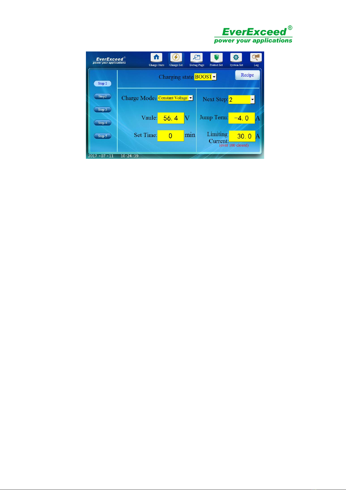
In this moment, setting three charging steps on the charger:
Step 1: Setting charging state as "boost" and the charging mode as constant current with 40A.
Time could be set as 0min (0 means the jump condition would not affect by time). Setting next
step as 2 and the jump term as 56.4V. The limiting voltage could be set as 100V.
Figure 5-6
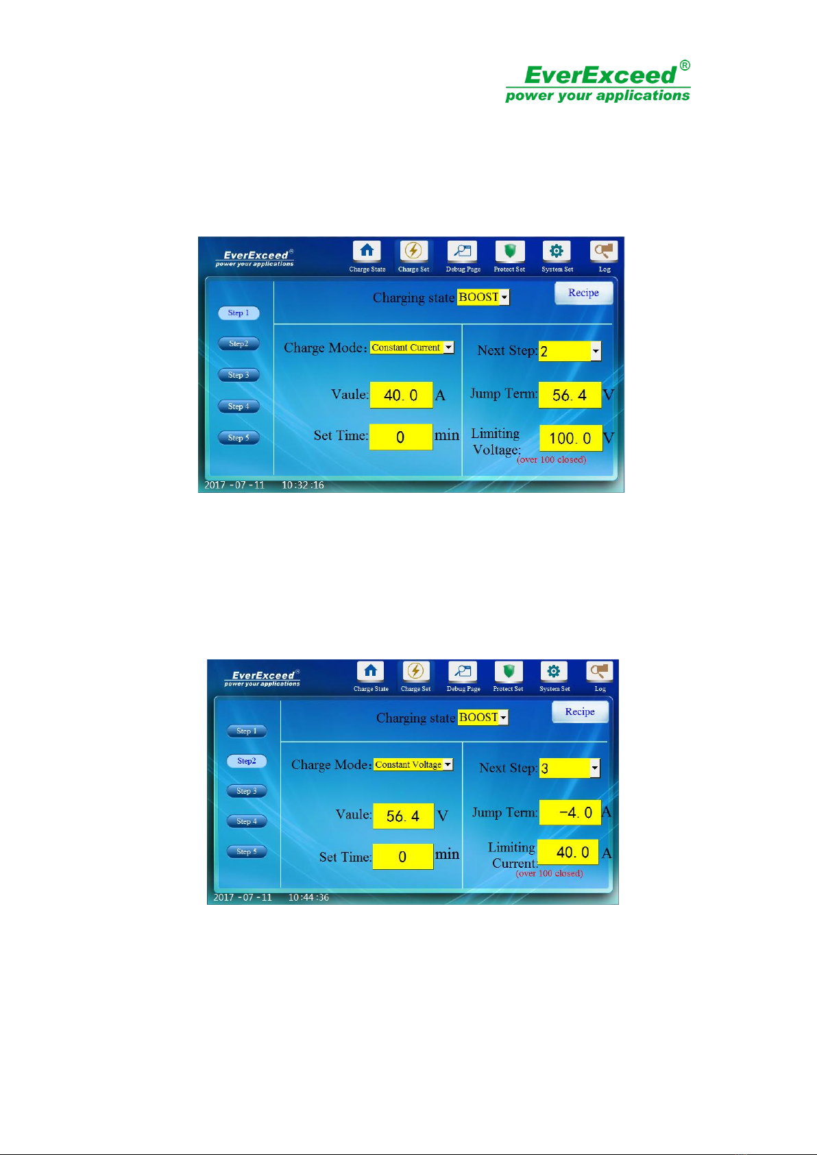
Step 2: Setting charging state as "boost" and the charging mode as constant voltage with 56.4V.
Time could be set as 0min (0 means the leaping condition would not affect by time). Setting
next step as 3 and the jump term as -4A. The limiting current could be set as 40A.
Figure 5-7
Step 3: Setting charging state as “float”and the charging mode as constant voltage with 54V .
Time could be set as 0min (0 means the leaping condition would not affect by time). Setting
next step as 2 and the jump term as 16A. The limiting current could be set as 40A.

16
Figure 5-8
5). Recipe screen
Recipe screen is designed for different batteries with different charging modes. It has five
recipes. All charging steps could be saved in recipe for convenient using. Clicking the "save
parameter" button could save charging step. Clicking "parameter download" button could
download the charging step to changing setting screen. For example, the charging setting of
the 48V200AH battery bank mentioned above has three steps. For convenience, it could save
the whole charging steps to the prescription which no need to inputting the charging steps
again. As showed in the figure 5-9.
Figure 5-9
6). Debug page
Debug page is a screen used for debugging the charger before it leaves the factory and it is not
accessible to the user. as showed in the figure 5-10.
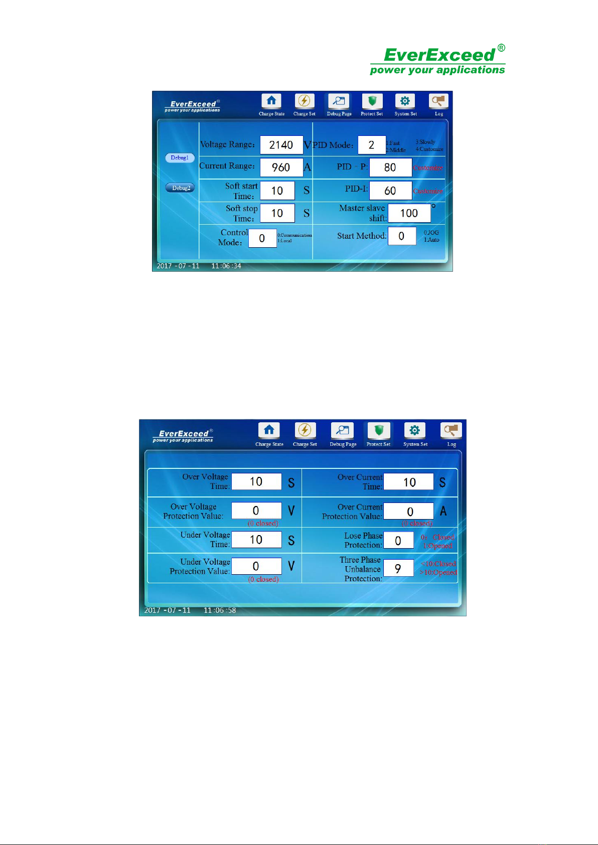
17
Figure 5-10
7). Protect Set
Protect Set page need a password to enter in and the screen could set the parameters of over
& under voltage protection, overload protection, phase-break protection and three-phase
imbalance. as showed in the figure 5-11.
Figure 5-11
8). System set
①
Language setting----setting the date, time brightness and language. as showed in the figure
5-12.
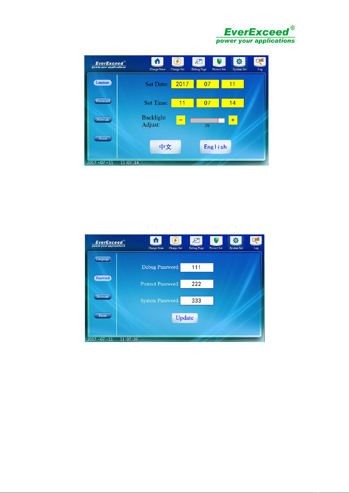
18
Figure 5-12
②
Password modification----modifying the debugging password, protection password and
system password. as showed in the figure 5-13.
Figure 5-13
③
network setting---- setting the parameters of IP address and remote control for the
charger.(please find the specific entering ways of remote control in remote control chapter). As
showed in the figure 5-14.
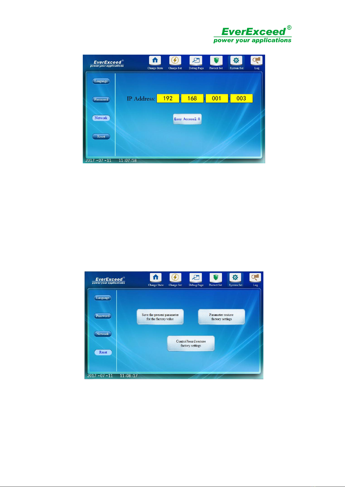
19
Figure 5-14
④
Factory reset
Saving the present parameters as factory reset value: saving all the values of charging setting
screen, debugging screen and protection screen as factory reset value.
Parameter factory reset: resetting the charger and the factory reset value shall be the present
value saved.
Charger panel factory reset: when the charger panel out of order or system halted, its function
is to restore the changer panel. as showed in the figure 5-15.
Figure 5-15
9). History log
On this screen, operator could check the history malfunction record and the history charging
record. as showed in the figure 5-16 and 5-17.
Table of contents
Popular Batteries Charger manuals by other brands


Sony
Sony NP-L90D operating instructions

TecMate
TecMate Optimate 3 TM430 Instructions for use

MSTRONIC
MSTRONIC SOL10P12 Series user manual

Intermec
Intermec CN3 Series quick start guide

Myenergi
Myenergi ZAPPI-2H07UB Operation & installation manual

Parkside
Parkside PDSLG 20 A1 Translation of the original instructions


